
Everything you need to create the sound of your dreams.
Introduction
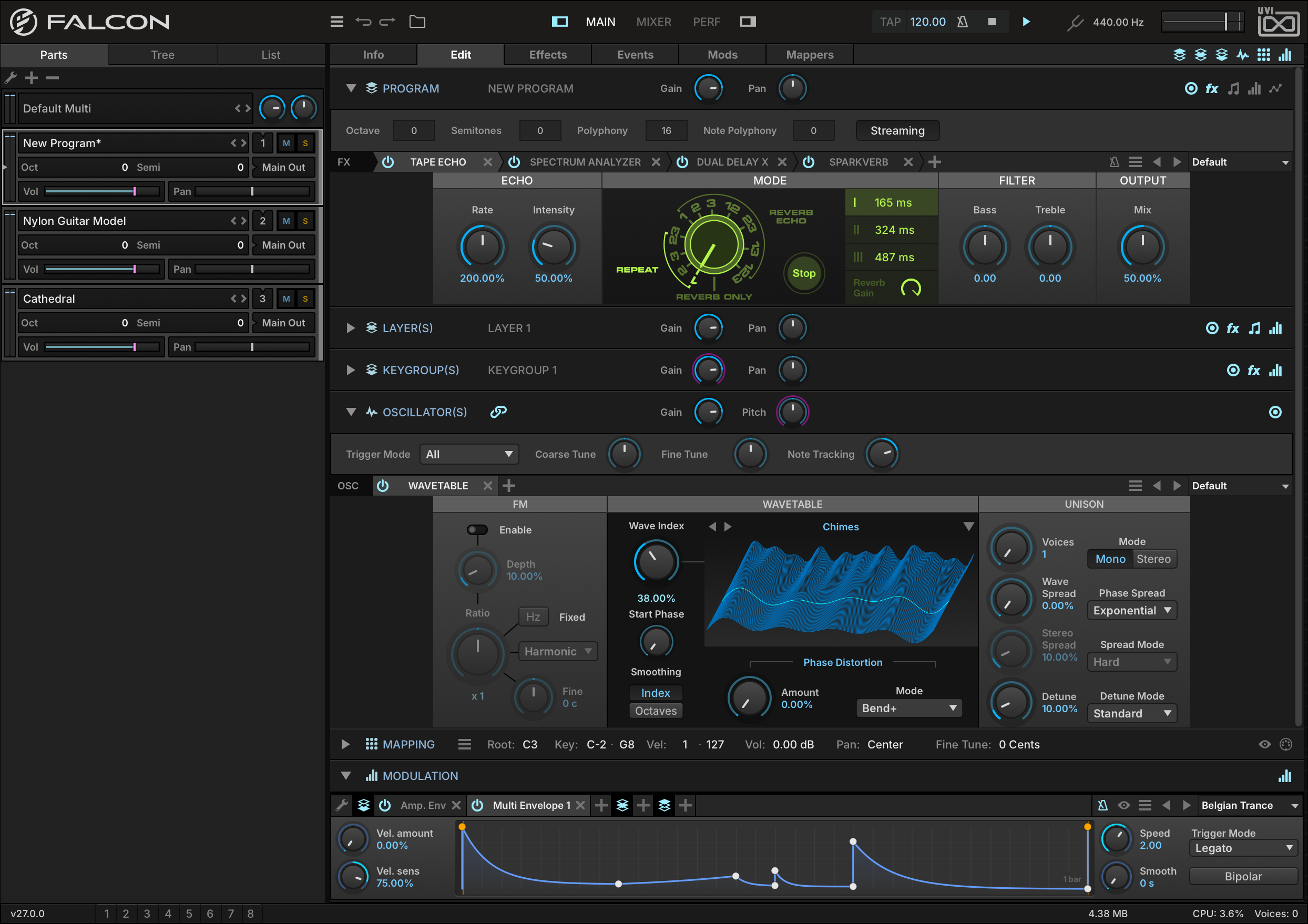
Falcon is more than an instrument: it’s your sound design universe. Built on a semi-modular architecture of oscillators, effects, modulators, and event processors, it lets you create and shape sound in any direction.
Whether you’re an experienced pro or just starting out, Falcon adapts to your workflow with a streamlined browser, flexible workspaces, and thousands of inspiring presets.
Wide Range of Sound Sources
Falcon includes 28 oscillators covering a wide range of modern synthesis methods from basic sample playback to more advanced generators like Pluck, Wavetable, FM Explorer and Spectral Stretch.
One of Falcon’s greatest strengths is its ability to freely layer oscillators to create elaborate hybrid instruments that capitalize on the unique features of both sample-based and algorithmic sound creation. There are no preset limits on the quantity or type of oscillators you can use; you’re limited only by your computer’s processing power and imagination.
Unique and Powerful Effects
Falcon includes over 90 high-quality effects, plus the legacy effects kept for older programs, categorized for easy navigation: Delays, Reverbs, Modulation, Filters, Equalizers, Amp and Stereo, Drive and Distortion, Dynamics, the all-new Pitch, Analysis and more. With effects suited for nearly every need from creative mangling to precise sound sculpting, mixing and analysis, Falcon provides a tremendous sound design facility.
Modulation
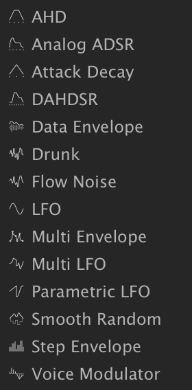
Falcon includes 16 modulators: AHD, Analog ADSR, Attack Decay, DAHDSR, Data Envelope, Drunk, Flow Noise, LFO, Macro, Multi Envelope, Multi LFO, Parametric LFO, Script Event Modulation, Smooth Random, Step Envelope and Voice Modulator. Modulation generators can be instanced at any level in a patch, allowing them to control nearly any parameter, be it on an oscillator, effect or even on another modulator. This system allows you to paint motion into your sounds almost effortlessly, from subtle variation over time to complex on-demand sequences.
Events and Scripting
Falcon’s Event section provides script-based control over pre-synthesis data, namely the manipulation, analysis or generation of MIDI notes and data. Event processors can do anything from arpeggiating incoming notes or strumming them like a guitar to applying micro tunings, playing back MIDI files or creating generative sequences. This MIDI can be used to control elements within Falcon, or routed to external software or hardware with MIDI Out.
Workflow
Falcon’s interface is adaptable to your needs, from exploring presets and editing sounds, to creating instruments, mixing multichannel performances, and more. Features like UI Snapshots, program templates, extensive preset implementation, and tree view make realizing your inspirations all that much faster.
Performance
Falcon was designed with a rich performance toolset including full MPE, Open Sound Control (OSC) implementation, host automation, flexible MIDI and audio routing, MIDI learn, key range and velocity range controls, keyswitching and more. Whether you’re working with a single instrument or an ensemble, in a DAW or standalone, Falcon gives you the control you need to create dynamic and captivating performances.
Sounds
Falcon comes with 1,600 high-quality factory patches crafted by top sound designers, covering classic synthesis, percussion, physical modeling, granular multi-oscillator hybrids and more. Each preset features an intuitive user interface and dedicated macro controls for easy performance and editing.
If you need more, Falcon is fully compatible with all UVI and UVI-Powered instruments from companies such as Acousticsamples and VI Labs. From vintage synths, samplers and drum machines to immaculate grand pianos, choirs and orchestras, Falcon is your gateway into some of the world’s most sophisticated and best-sounding instruments.
End User License Agreement and System Requirements
Installation
Install Falcon
UVI Portal
1. Open UVI Portal and Log In to Your UVI Account
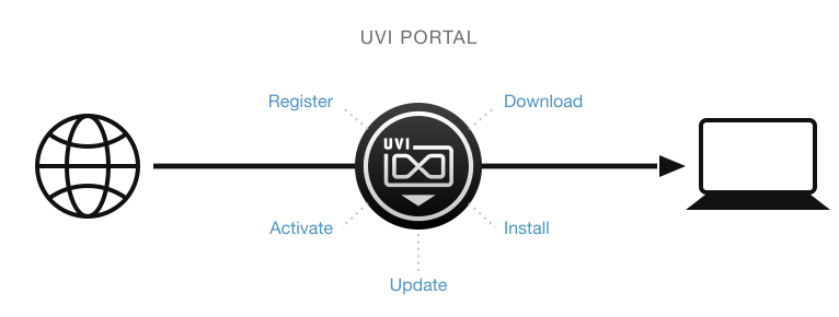
UVI Portal lets you register, download, install, activate and update all of your UVI products in a single convenient location. Click one of the links below to download and install UVI Portal for your system:
If you are a SonicPass member, please refer to this article to download and install your products, including Falcon.
2. Register Your Serial Number and Link it to Your iLok Account
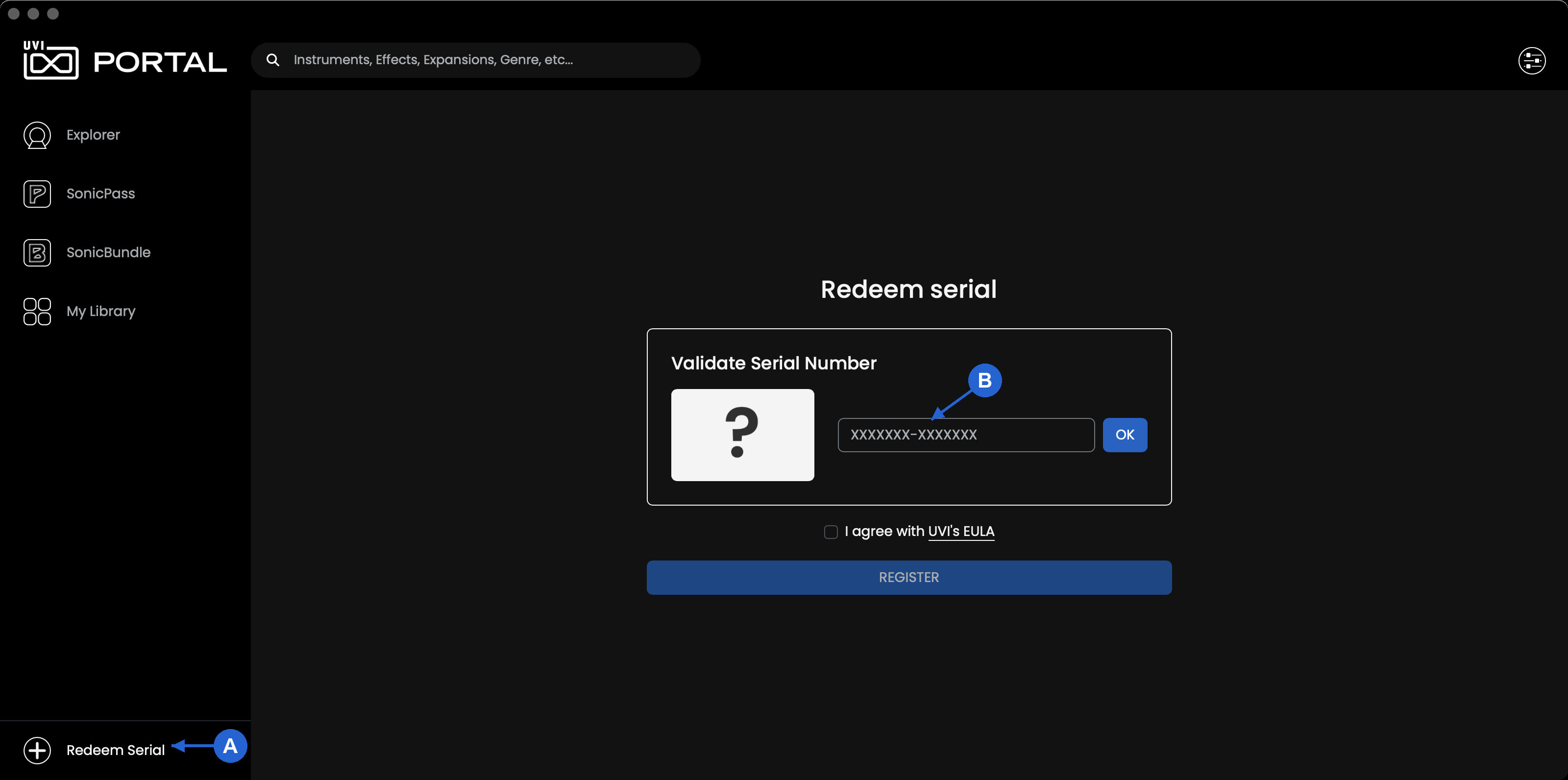
A - Click Redeem Serial at the bottom of the sidebar to start
B - Enter the serial number, then follow the prompt to enter your iLok ID or create an iLok account if you don’t have one
3. Download and Install Falcon by Clicking on the Install Button — Falcon Factory needs to be installed separately.


4. Finish by Activating Falcon with iLok License Manager
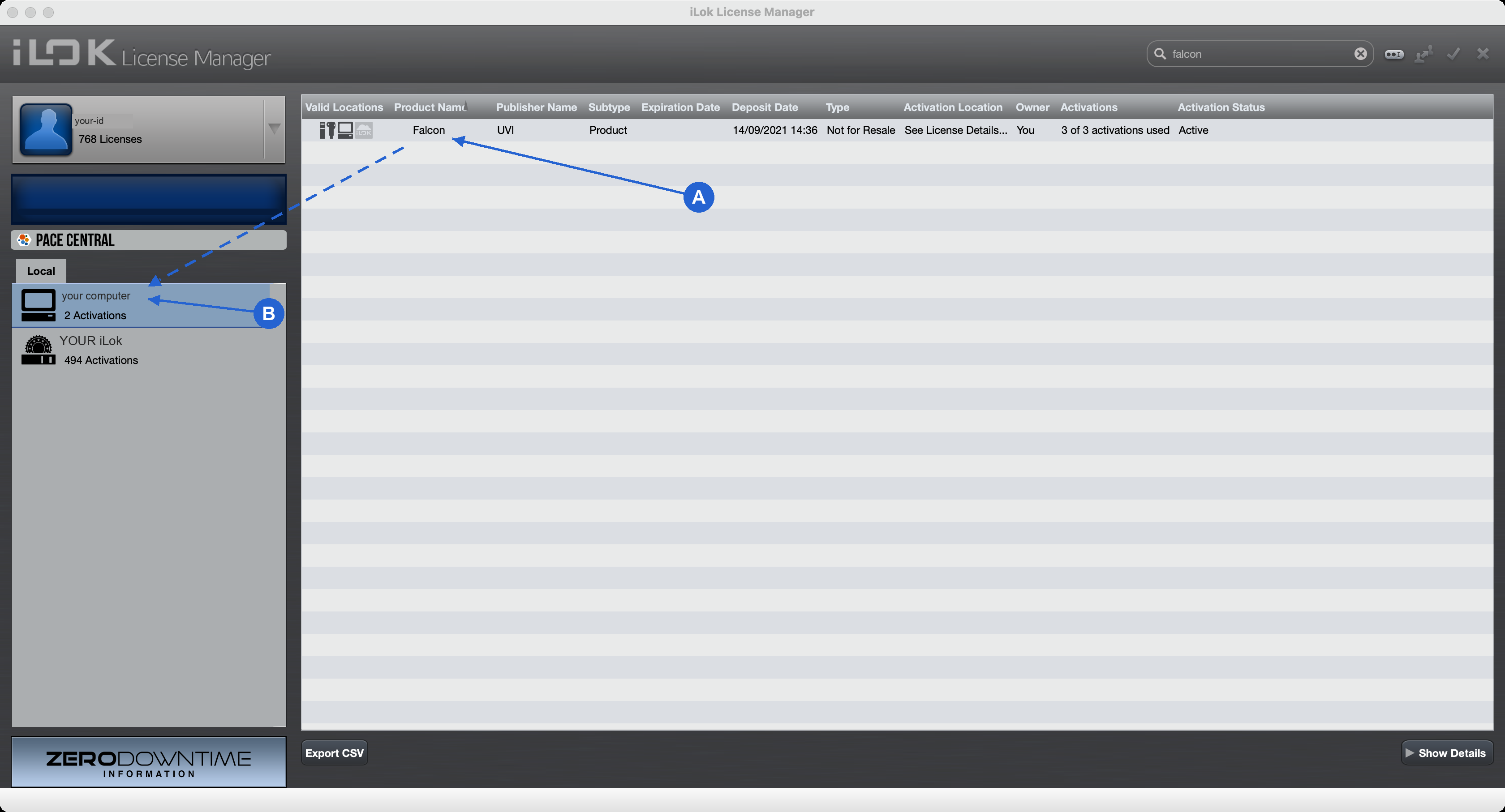
Click the activate button in UVI Portal to open the iLok License Manager app.
A - Find the Falcon license in the list
B - Drag and drop it onto your computer in the Local list on the left
Please refer to the UVI Portal Manual for more details.
Startup Screen
Startup Screen
- Launch Falcon.
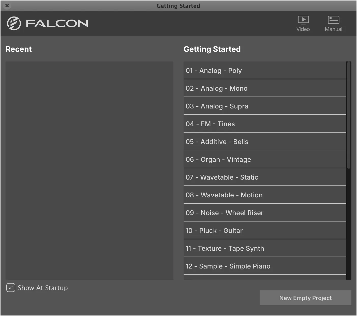
The startup screen provides quick access to the program templates as well as recent patches.
- Select from the options:
The templates cover a range of setups, including many types of synths, samplers, MPE and more. Program templates are a fantastic way to jump-start your creative process. You can even create your own!
-
A. Select a template from GETTING STARTED.
-
B. Select a RECENT program.
-
C. Click NEW EMPTY PROJECT to start from scratch, or select a patch from your Soundware.
Other Options
-
The small X button in the upper-left corner closes the screen.
-
Uncheck SHOW AT STARTUP to launch Falcon without this screen.
-
VIDEO opens Falcon videos on YouTube in your web browser.
-
MANUAL opens this manual in your web browser.
Audio & MIDI Devices (Standalone)
Configure I/O
1. Launch Falcon
If you plan to use Falcon in standalone mode, you may need to select which MIDI inputs and audio outputs you want Falcon to use. This only needs to be done the first time you launch Falcon, or if you make changes to your hardware (such as changing your audio interface or controller keyboard), as these settings will be saved and reloaded the next time you start Falcon.

2. Select ‘Audio and MIDI Settings…’ from the Menu
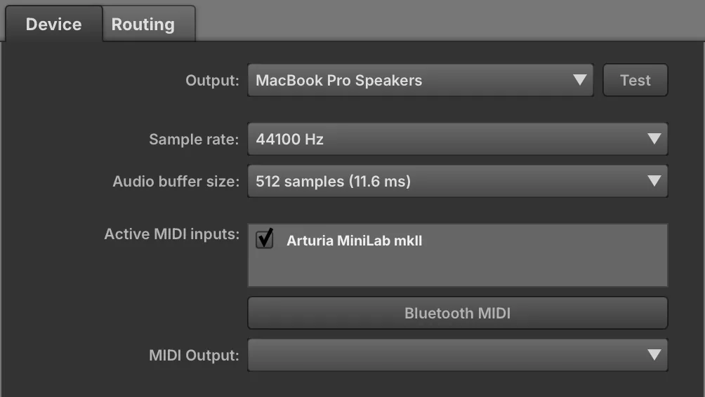
3. Select the Desired Audio and MIDI Devices…
If you intend to use Falcon primarily as a plug-in you can skip this step, as the audio and MIDI settings will be defined by your host DAW.
Device
Select the desired audio interface from the Output menu, click to activate the available output channels, then select the sample rate and buffer size from the menus.
Click to activate the available devices or sources for MIDI input.
All incoming MIDI inputs are merged, but channels remain discrete.
On each Falcon part, select OMNI to listen to all channels, or A1–A16 to listen to a specific channel.
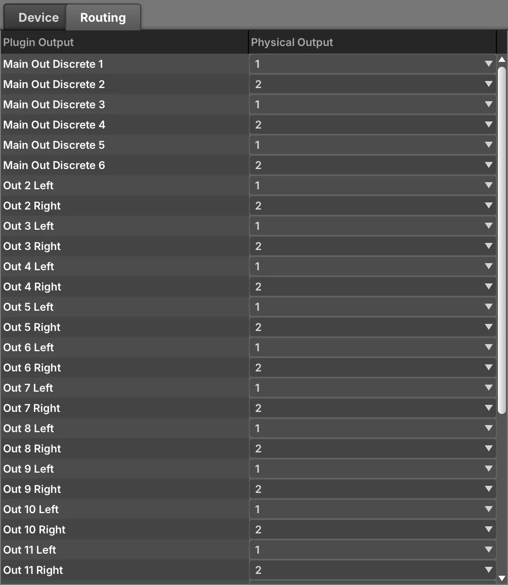
Routing
Falcon can address up to 17 stereo outputs. Use this panel to link Falcon’s outputs with those of your audio interface.
Load Your Soundware
Preset Browsing
- Launch Falcon.
UVI-Powered Soundware is high-quality sound and instrument content from UVI and partner developers. Soundware and Falcon Expansions are fully supported and seamlessly integrated in Falcon.
- Double-click EMPTY in the Parts List to open the Library Browser.

To use Falcon Factory (and Soundware) in Falcon you just need to tell it where to find them.
- Click the FILES tab to switch to the File Browser, and expand its SOUNDWARE section.
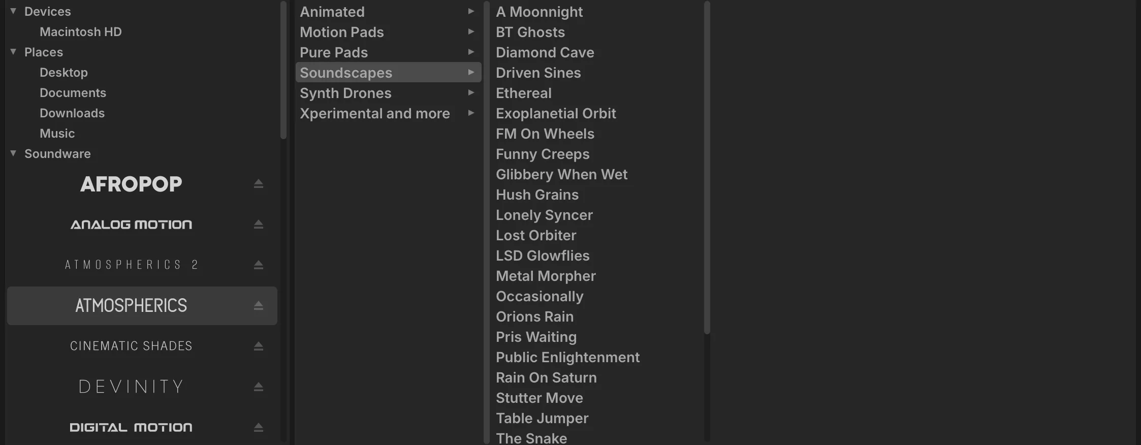
You can change the Soundware location, for example to an external drive.
- Select a Soundware, then a category and a patch. Double-click the patch to load it.
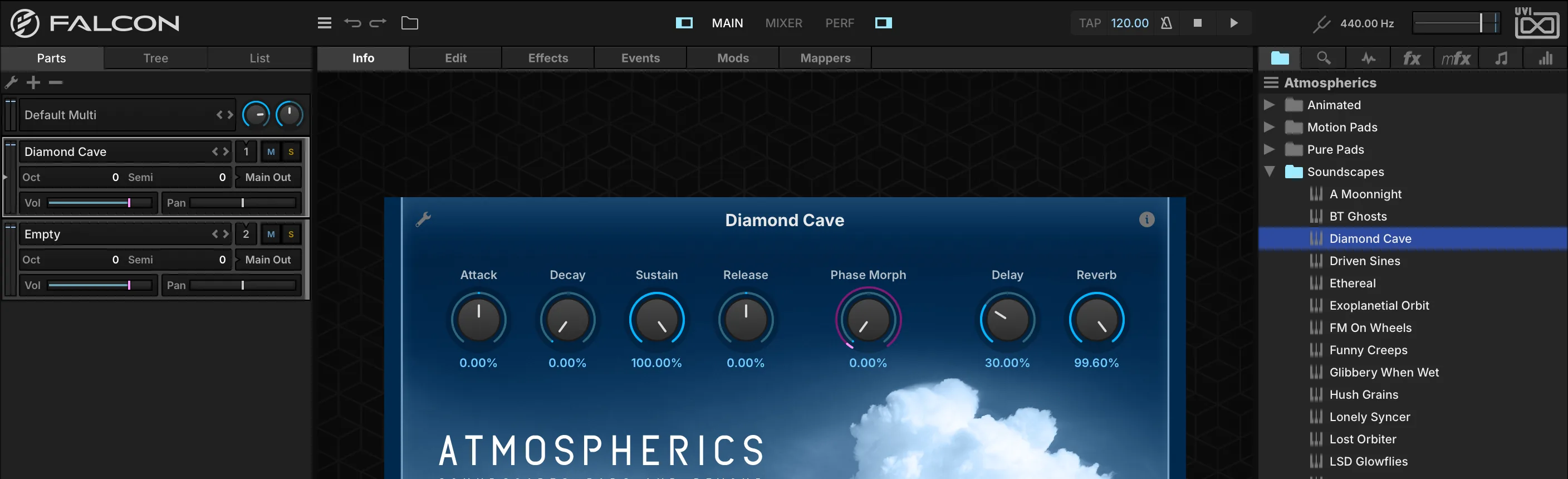
To manage your Soundware location, open the preferences panel of UVI Portal, or the Soundware tab in the preferences panel of UVI Player or Falcon.
NOTE: If you commonly use UVI Player it is recommended that you place your Soundware files and Falcon Expansions in separate directories.
- Close the browser, and you’re ready to jam!
Learning: Basics + Synthesis
Synthesis
The following section will illustrate the basics of using Falcon, from loading and saving patches to creating a number of common sounds and instrument setups from scratch. It’s a perfect place to start if you’re new to Falcon and need some quick tips to get going.
Falcon’s synthesis engine offers a wide range of tools for playing, editing, and creating instruments and samples. You can freely mix sounds created with pure synthesis and sample playback even in the same program. Each of Falcon’s oscillator types has a different speciality; only a few of the possibilities are explored here.
Before continuing, check that you have your audio and MIDI devices connected and working properly. Additionally, some of the following examples use programs and samples from UVI Soundware. It’s recommended to have the “Falcon Factory rev2.ufs” Soundware available to follow along with most of the examples.
The Falcon Factory rev2 Soundware is available through UVI Portal and the My Products page on UVI.net.
Working with Presets
Loading and Tweaking a Preset
-
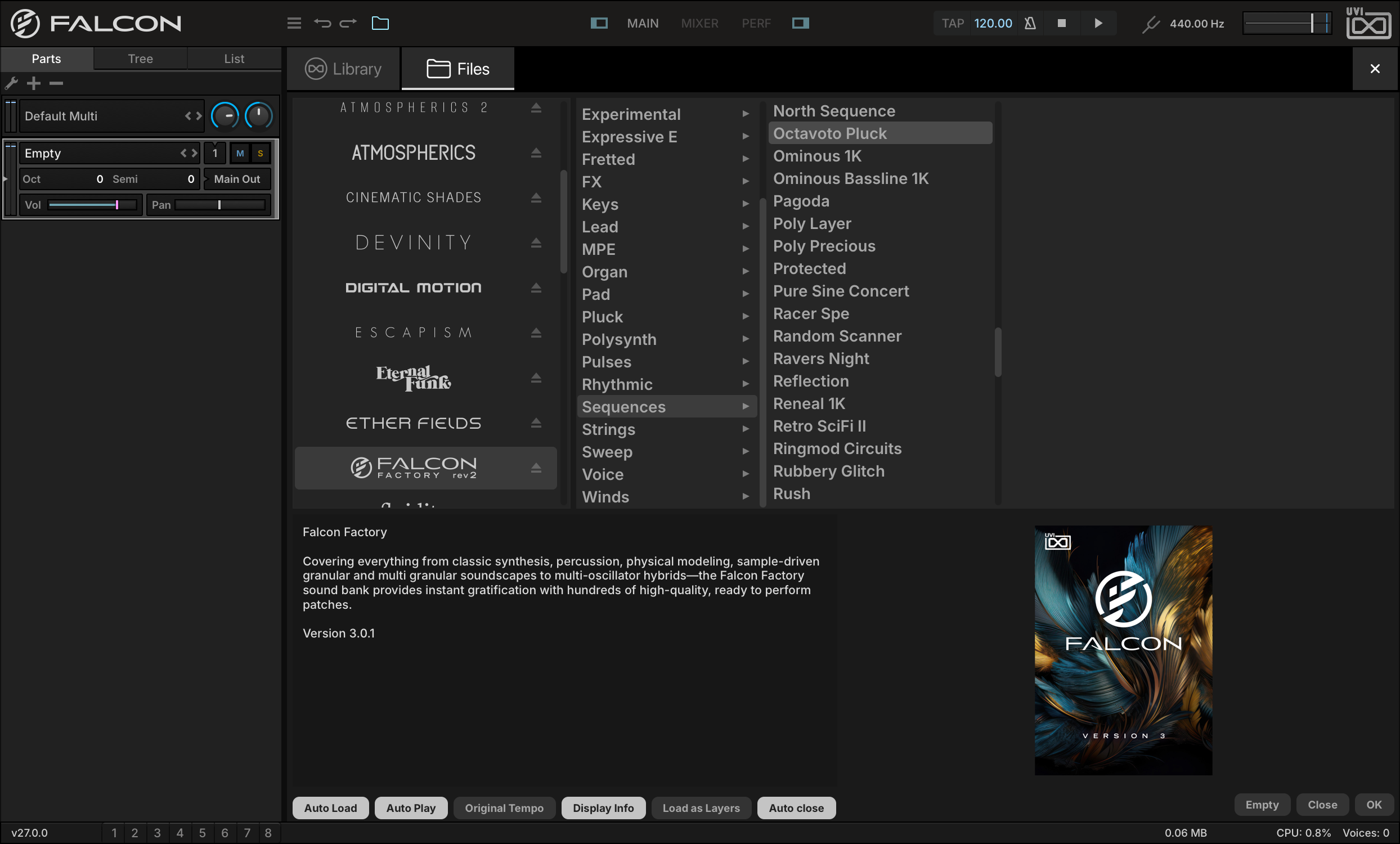
Let’s start by loading a sound from the Falcon Factory rev2. Double-click the part name (EMPTY) in the Parts List to open the Library Browser, then click its FILES tab to switch to the File Browser.
-
Falcon Factory rev2 will appear in the Soundware section of the File Browser. Select the FALCON FACTORY REV2 Soundware, then SEQUENCESOCTAVOTO PLUCK.
The lower half of the browser shows information about the selected program, sometimes with tips for playing it. Press OK or double-click the program name to load it. The Main view now displays the parameters of the loaded program. The Info tab shows the “front panel” of the program with macro controls for commonly used settings, and the Edit tab shows all of the program’s parameters.
-
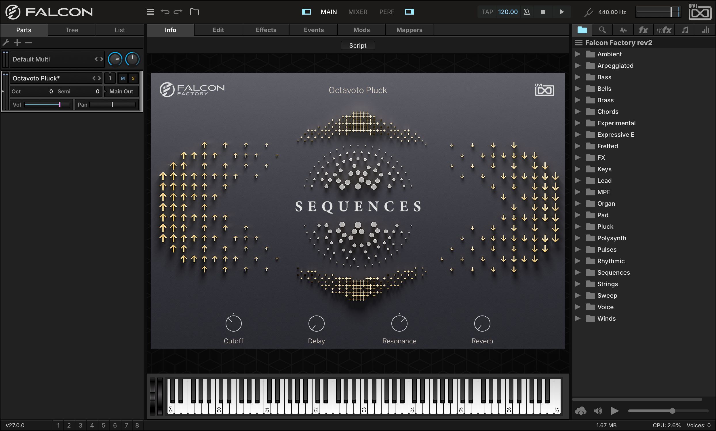
Let’s go to the INFO tab first. Here we can see the instrument’s macro controls and an on-screen keyboard. Press the keys on the keyboard to trigger a note, or play a note from your MIDI controller. You should hear the instrument now. If your MIDI controller stays silent, try the on-screen keyboard first: if it is silent too, check your audio settings; if it plays, check your MIDI settings.
Like every Falcon Factory rev2 program, Octavoto Pluck draws its own front panel with a script. To see a description of the instrument, press the SCRIPT button at the top of the Info tab to switch to the standard view, then press the Info “i” button in the upper right.
-
Let’s make some changes to the program, by adjusting the CUTOFF and RESONANCE macro controls. Click a knob and drag to adjust it. You can also hover over a control and turn your mouse’s scroll wheel, or scroll with your trackpad.
-
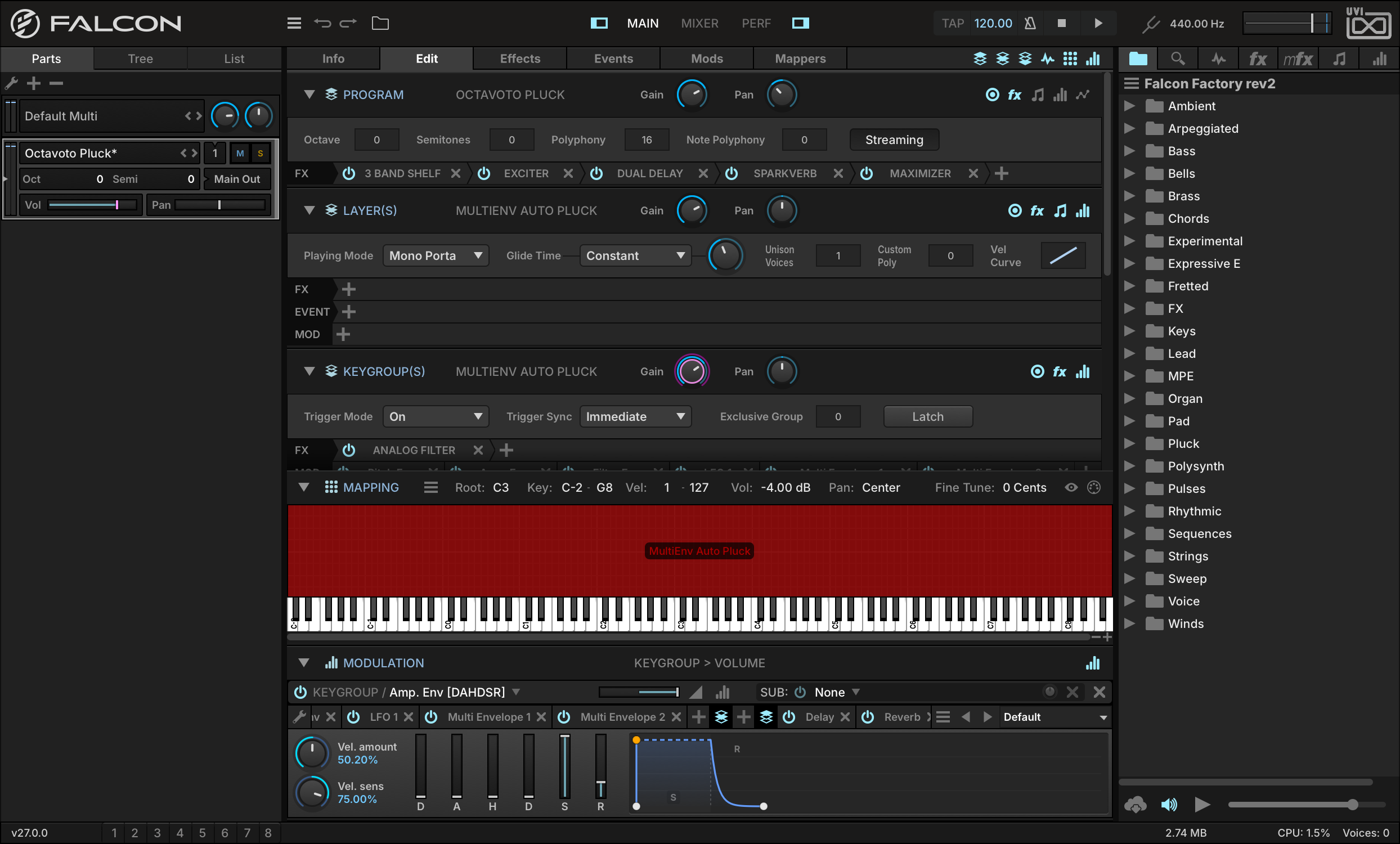
That’s a start, but to dig in a little deeper, let’s switch to the EDIT tab. Here we can see the settings for the major components of the instrument: program, layer, keygroup, and oscillator. Additionally, the Sample Editor, Mapping Editor, and Modulation Editor provide editing of sample files, the mapping of the layers and keygroups, and modulation assignments.
-
Let’s make some edits to the instrument. To change the program’s output level and panning, go to the PROGRAM section and adjust the GAIN and PAN settings.
-
Let’s also change the instrument from polyphonic to monophonic. Go to the LAYER section and change Play Mode to MONO PORTAMENTO, and adjust GLIDE TIME to change the amount of “slide” between notes.
Saving a Program
-
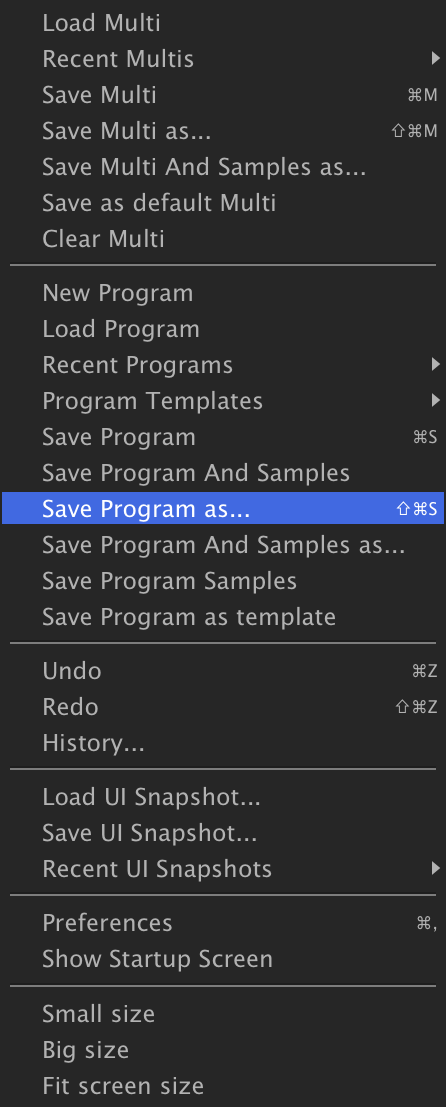
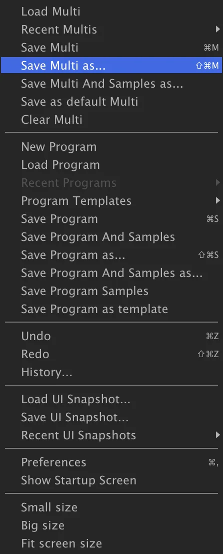
Now that we’ve made some changes to the program, let’s save our edited version. The main menu in the toolbar is a central location for many of Falcon’s save/load options. From the Main Menu, choose SAVE PROGRAM AS.
Choose the location where you’d like to save the file, enter a file name, then Save — your edited program is now saved with a new file name. The original program file is unchanged, and your edits are saved under the new program.
If you make some more edits to this program, you can save the same file again with Save Program. That will save the same file in place, and won’t prompt again for a file name.
-
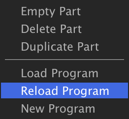
If you’d rather discard changes you’ve made since the last time you saved the file, you can instead choose to reload the program file. Right-click the part in the Parts List and choose RELOAD PROGRAM from the context menu to undo all of those changes.
Saving a Multi
-
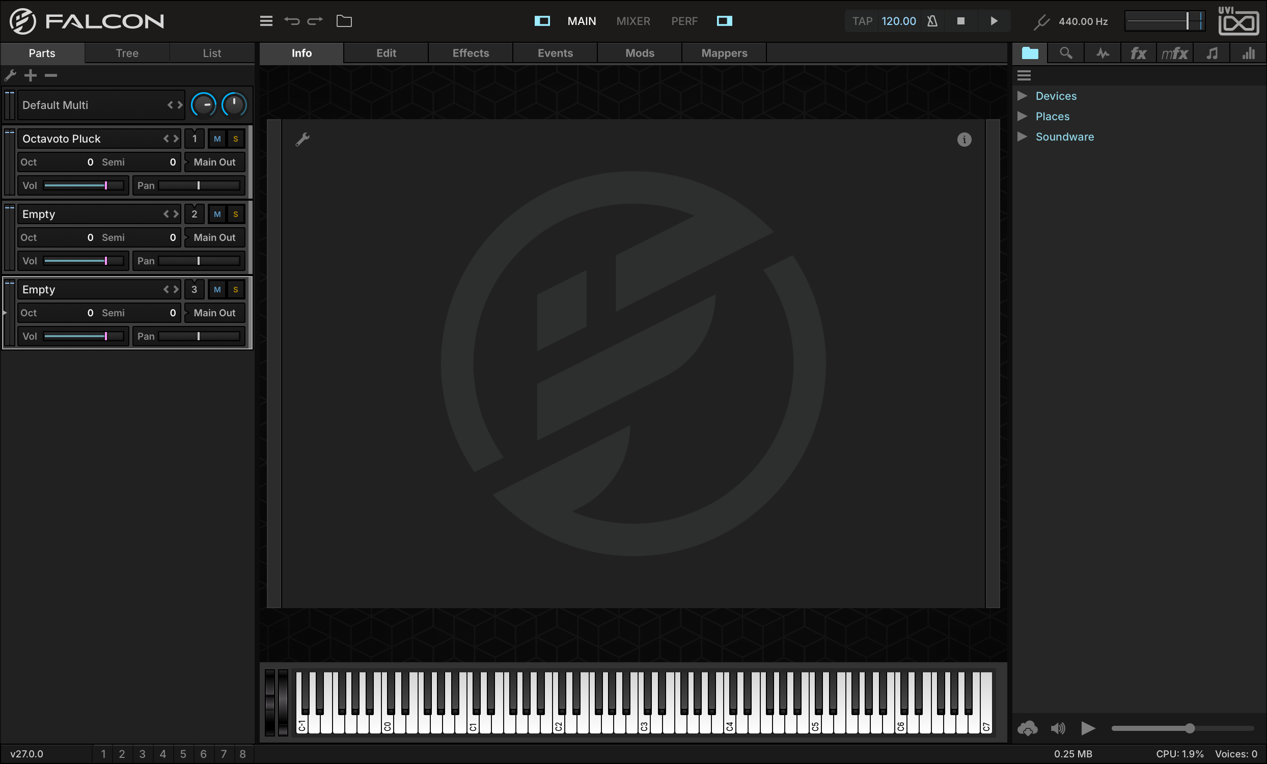
Now that we have one instrument loaded and edited to our liking, let’s load some additional sounds. In the Parts List, press the + button to add a few more parts.
-
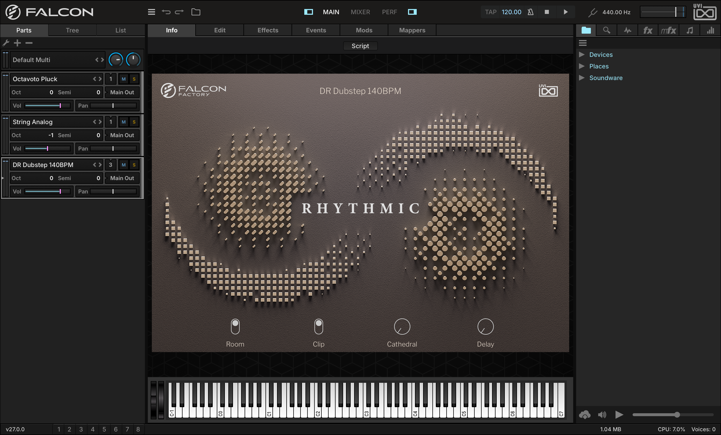
Let’s load a few more sounds from the Falcon Factory rev2 Soundware, such as the PADSTRING ANALOG instrument and RHYTHMICDR DUBSTEP 140BPM, or choose a slice drum loop file from other UVI Soundware or from your own library and start building a multi-timbral multi.
-
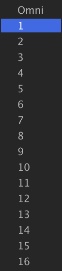
To stack parts 1 and 2, set the MIDI input of parts 1 and 2 to channel 1. Play a few notes from your MIDI controller — you should now hear both parts trigger at the same time. (The on-screen keyboard only ever plays the selected part, so it cannot play both.)
-
Now let’s adjust the parts relative to each other: reduce the volume of part 2 to −12 dB, and transpose part 2 by setting OCT to −1.
-
On part 3, just press any note to play the rhythm. If you load your own drum loop, press PLAY on Falcon’s toolbar and you will hear the drum loop auto-play, synced to Falcon’s tempo. Edit Falcon’s tempo, and the rhythm automatically stays in sync.
-
Now with our multi taking shape, let’s save it. From the Main Menu in the toolbar, choose SAVE MULTI AS.
All of the details about this instance of Falcon are saved in the multi, and can be recalled with this single file.
Make a Simple Synth
-
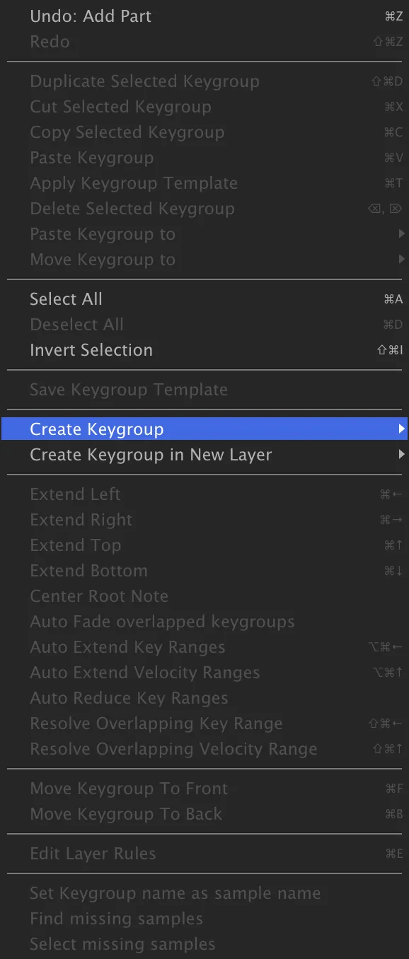
Now that we’ve looked at editing existing sounds, let’s start creating some new ones from scratch. In an empty part, go to the EDIT tab. In the MAPPING EDITOR, right-click and choose CREATE KEYGROUPSYNTH TEMPLATE.
-
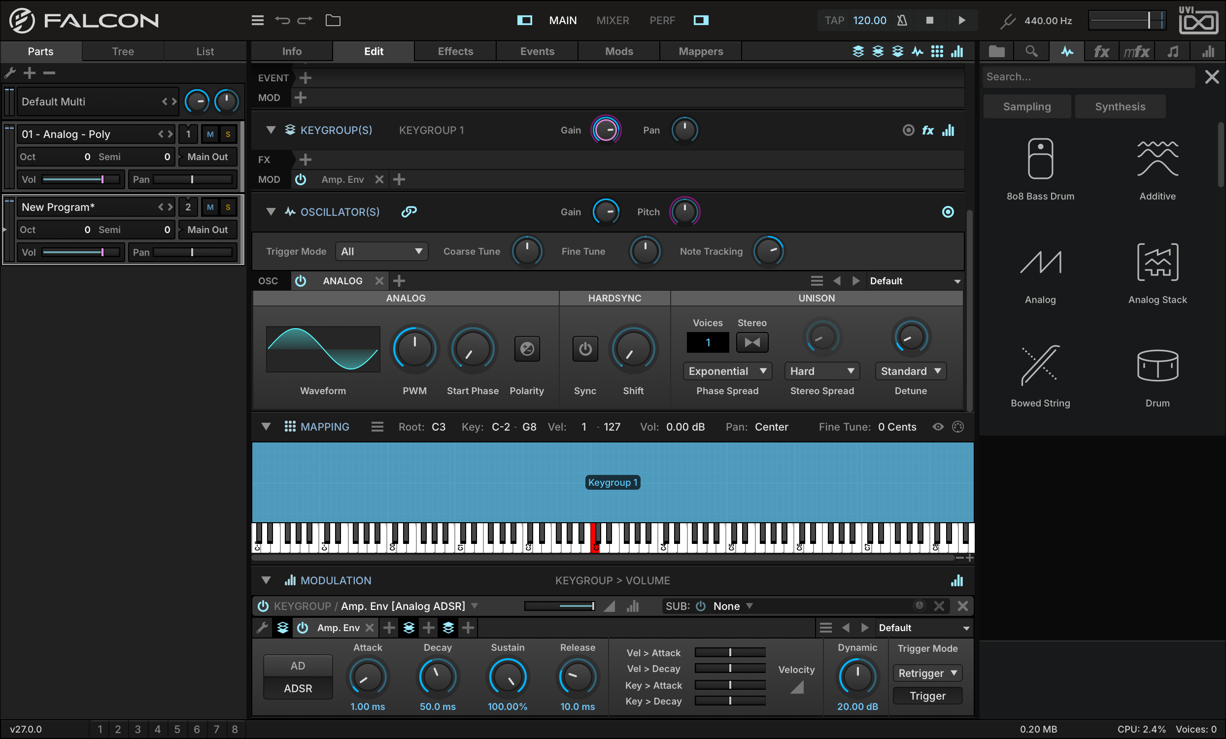
A new keygroup has been created, mapped to the full key and velocity range.
-
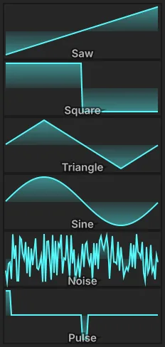
Play a few notes, and you’ll hear the Synth Template’s Analog oscillator playing a simple sine wave. Let’s change that to a sawtooth wave, by clicking the WAVEFORM and choosing SAWTOOTH from the menu.
-
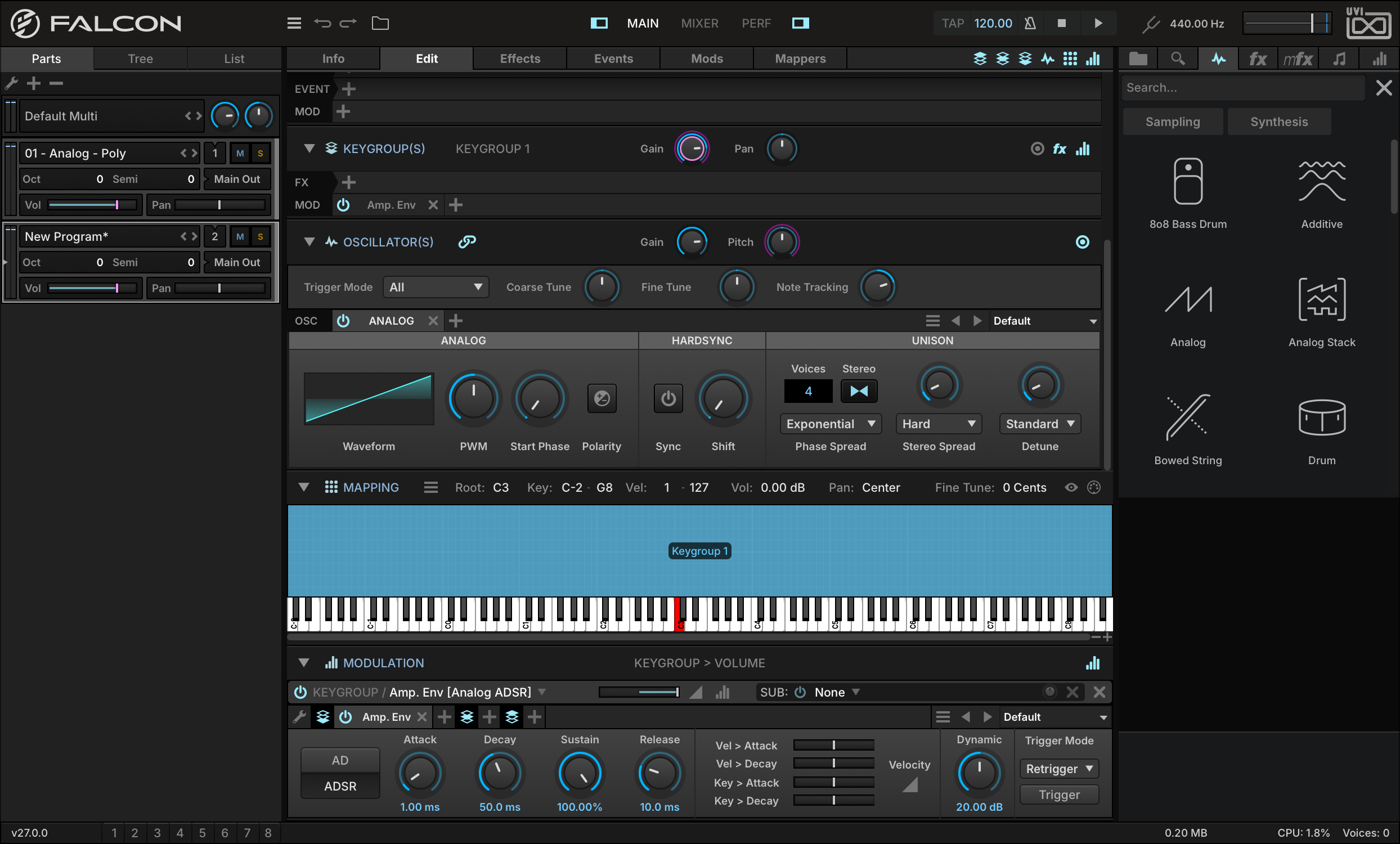
We can continue building our sound by editing the other synth engine parameters, such as enabling Stereo mode and adding additional voices.
-
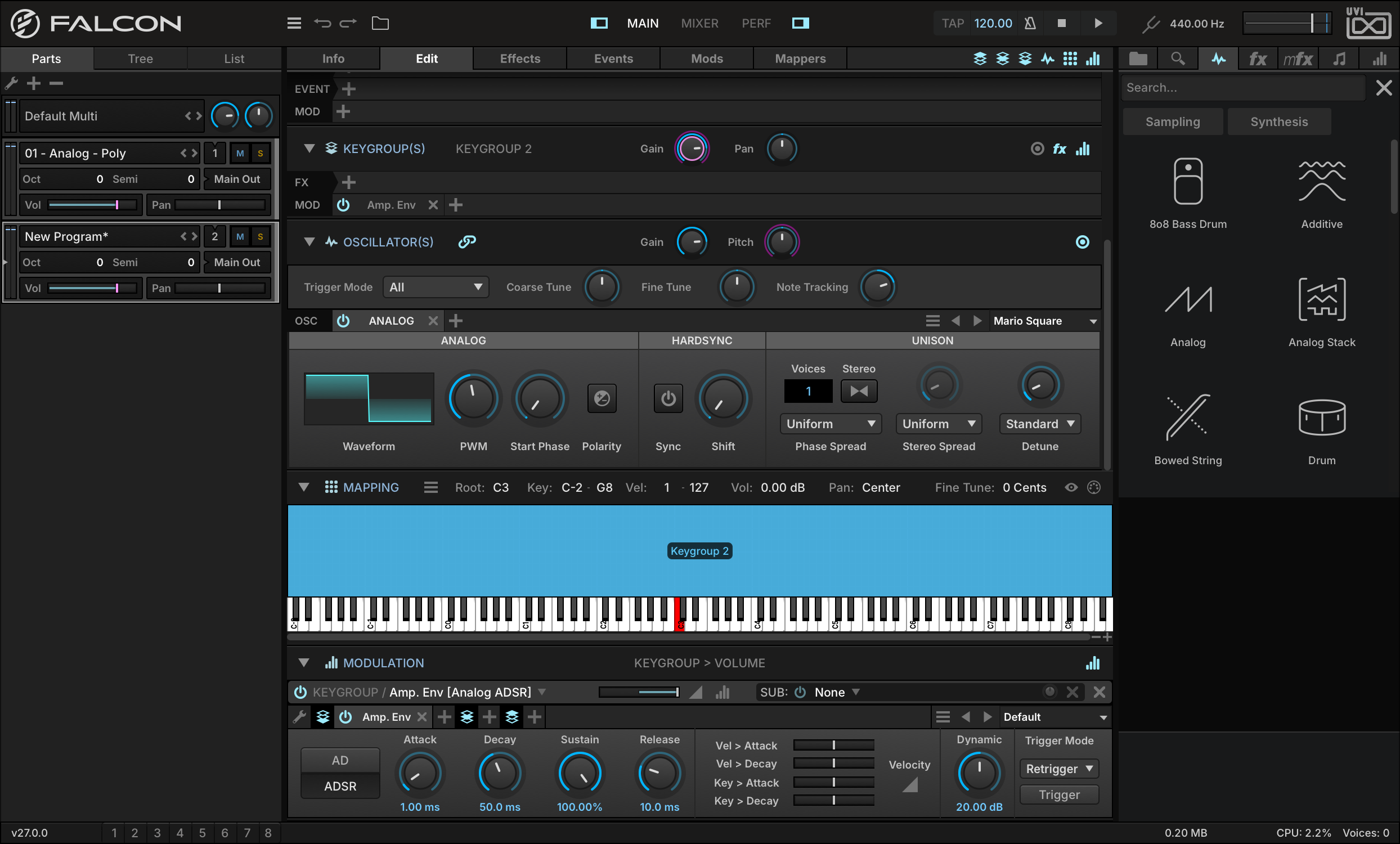
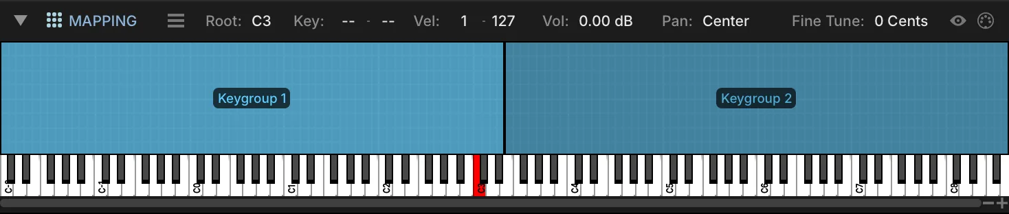
To stack multiple synth sounds, we can add a second synth keygroup. Let’s choose CREATE KEYGROUPSYNTH TEMPLATE a second time, and another keygroup will be stacked on top of the first. For this keygroup, let’s choose one of the oscillator’s factory presets, such as MARIO SQUARE.
-
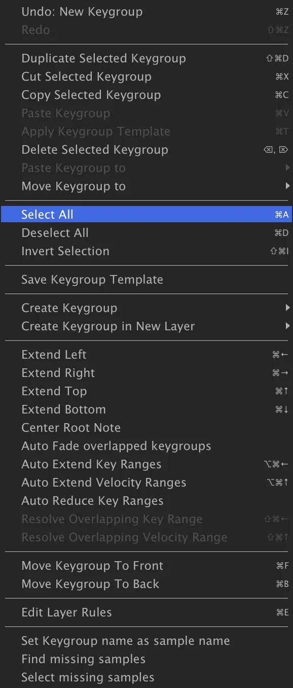
Perhaps instead of stacking these sounds, this could be a split program instead, with one sound for the left hand and another for the right hand. To do that, we’ll need to adjust the key ranges of the keygroups so they don’t overlap. Right-click in the Mapping Editor and choose SELECT ALL, then choose RESOLVE OVERLAPPING KEY RANGE.

-
Make an Arpeggiated Synth
Falcon has numerous synthesis options in addition to the classic virtual analog oscillator we’ve already seen. Let’s explore the FM (frequency modulation) synth oscillator, using one of the factory presets as a starting point.
-
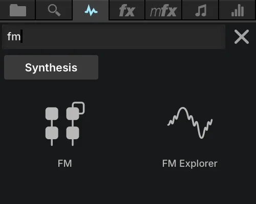
Open the right-hand sidebar and choose the OSC tab. Press SYNTHESIS, or type a name in the search field, then drag the FM oscillator to the MAPPING EDITOR.
-
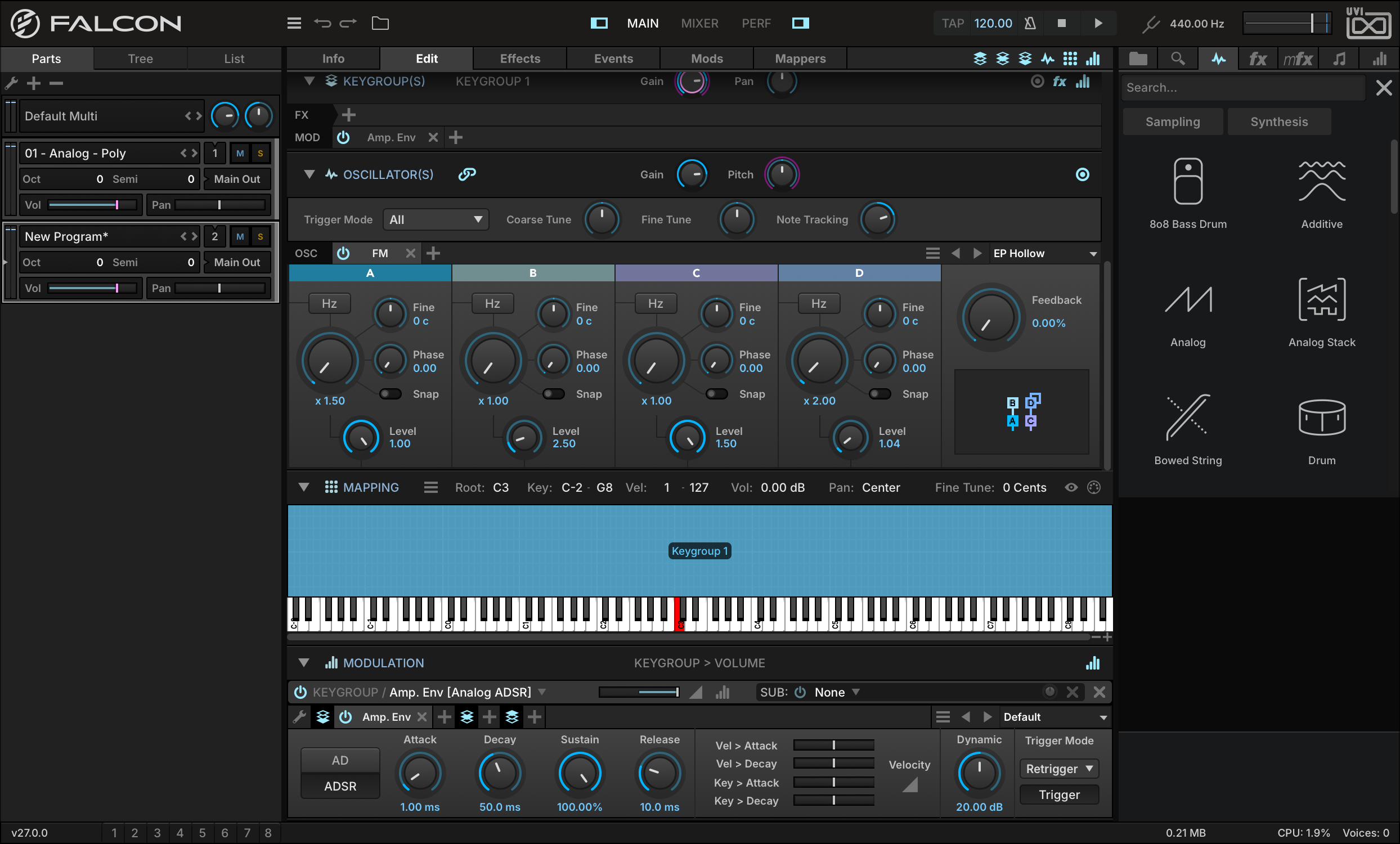
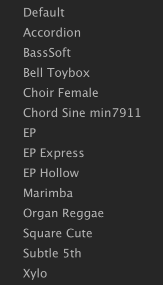
While playing a few notes, press the next or previous buttons in the oscillator module to browse the presets. Let’s choose the EP HOLLOW preset and build from there.
-
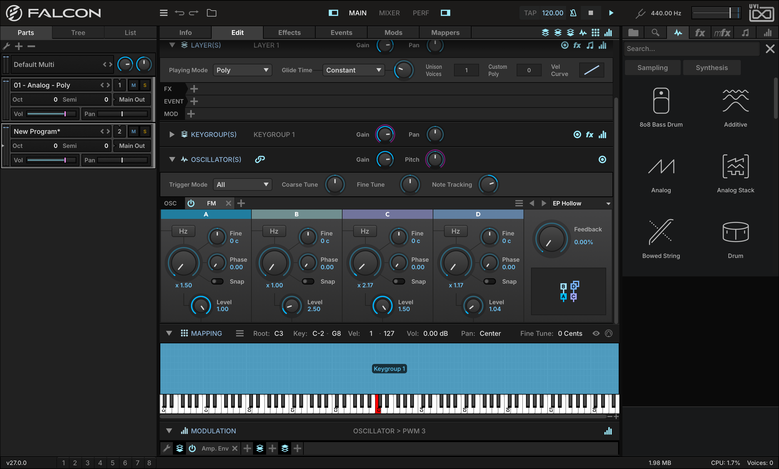
The FM oscillator has four operators (A, B, C, and D), and each operator’s frequency is a ratio to the base note. For example, a ratio of 2.0 means the frequency is doubled, or one octave up from the base note. Integers and simple ratios (3/2, 4/3, etc.) create some of the more obvious harmonic relationships, but the ratios are fully adjustable and small changes can create interesting and unexpected results. Let’s set the RATIO of operator C to 2.17 and that of operator D to 1.17, and hear the difference.
-
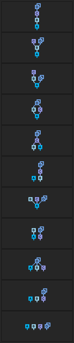
The operators can also be arranged in a variety of topologies. Using the same ratios, different topologies can change the sound drastically. To change the topology, press on the topology diagram in the lower right and choose a topology from the menu. For example, change the TOPOLOGY from #8 to #7.
Now that we’ve customized the sound source, let’s make it more dynamic by adding an arpeggiator.
-
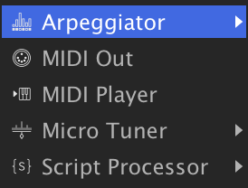
Switch to the EVENTS tab, press the + button, and choose ARPEGGIATOR.
-
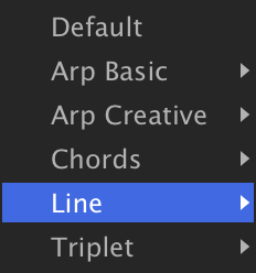
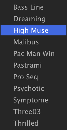
To load one of the factory presets, press on the PRESET MENU and choose one from the menu. Let’s choose one of the sequenced pitch presets, such as ARPEGGIATORLINEHIGH MUSE.
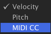
Press and hold a few keys to hear the arpeggiated sequence. There are actually three layers to the arpeggiator: note velocity, pitch, and MIDI CC. To view the different layers, right-click the step grid and choose the layer from the menu.
-
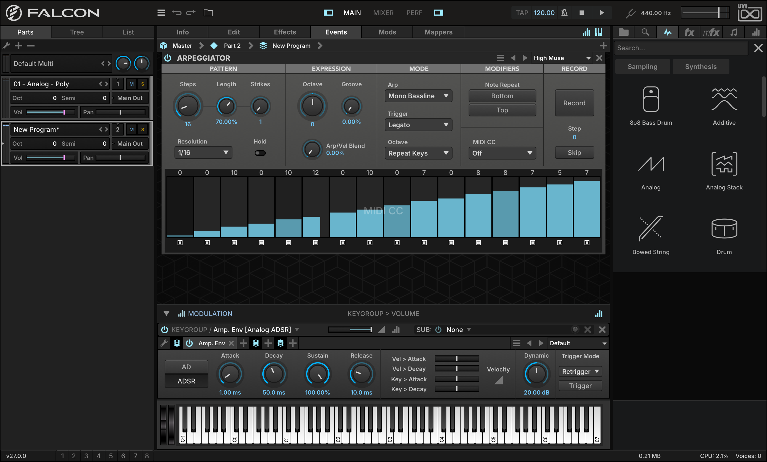
Let’s use the MIDI CC layer to generate a control source for modulating the FM operators. Switch to the MIDI CC layer, then press and drag across the step grid to enter step values.
-
Then choose a MIDI CC for the arpeggiator to output; a general-purpose MIDI CC such as 16 is a good choice.
-
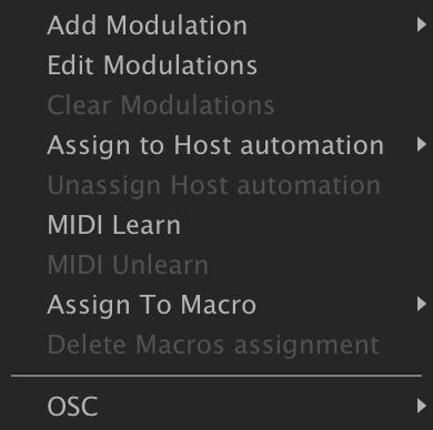
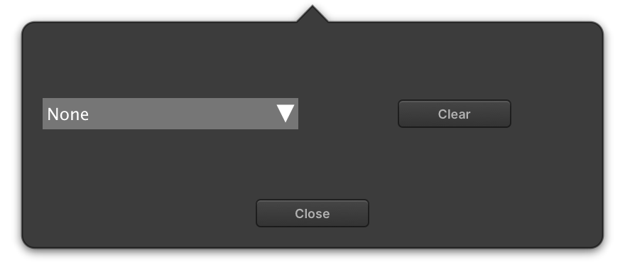
Switch back to the EDIT tab, right-click the FEEDBACK knob, and choose MIDI LEARN. In the pop-up, choose MIDI CC 16 from the menu, then close the window.
Press and hold a note, and you’ll see the value automating in sync with the arpeggiator sequence. Let’s also slow the tempo down just a bit: double-click the tempo in the toolbar, type a new value and press Return. Since the arpeggiator is tempo-synced, it will automatically adjust when Falcon’s tempo changes.
Make an Evolving Pad
Now let’s build a pad sound, one that evolves over time by using modulation to create movement.
-
In an empty part, create a new synth keygroup.
-
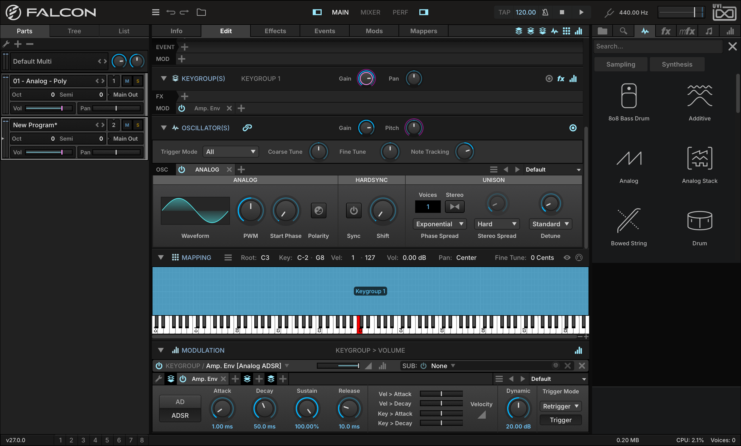
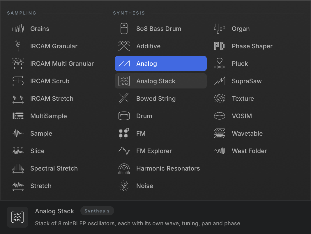
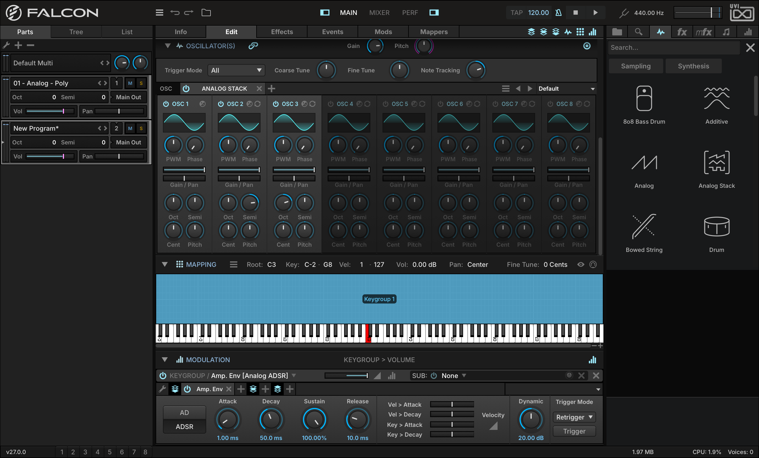
This time, let’s use the Analog Stack synth; right-click the oscillator name to open the oscillator chooser, and pick ANALOG STACK from it.
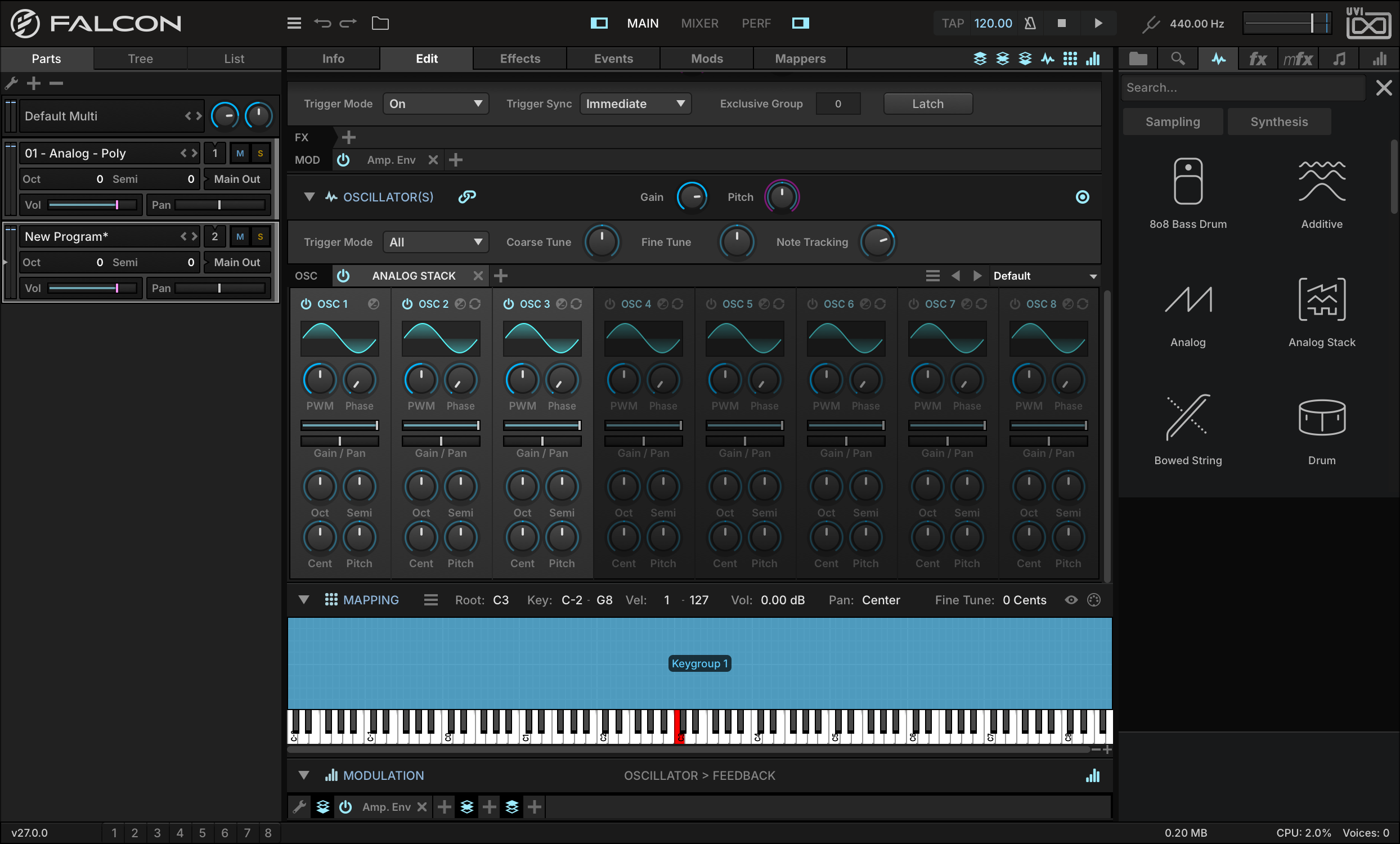
The Analog Stack starts with the same basic options as the Analog oscillator type, but offers a unified bank of eight oscillators for quickly creating stacked sounds.
-
Press the POWER button on oscillators 2 and 3 to enable them. Each oscillator has independent controls for its waveform shape, gain, pan, pitch offset, and so on.
-
Let’s set oscillator 2’s pitch offset to +7 semitones from oscillator 1, and oscillator 3 to +1 octave.
-
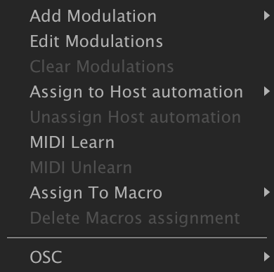
We can also modulate each oscillator independently. To add a new modulation source for oscillator 2’s pulse width modulation, right-click its PWM knob and choose ADD MODULATION.
-
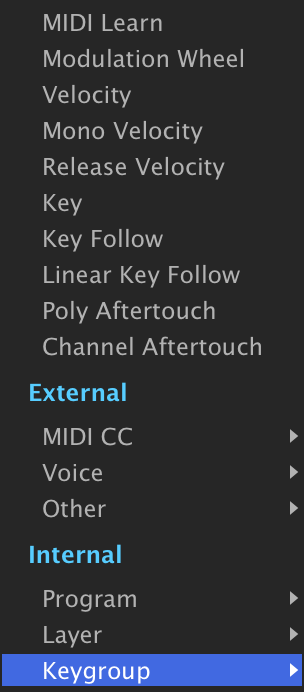
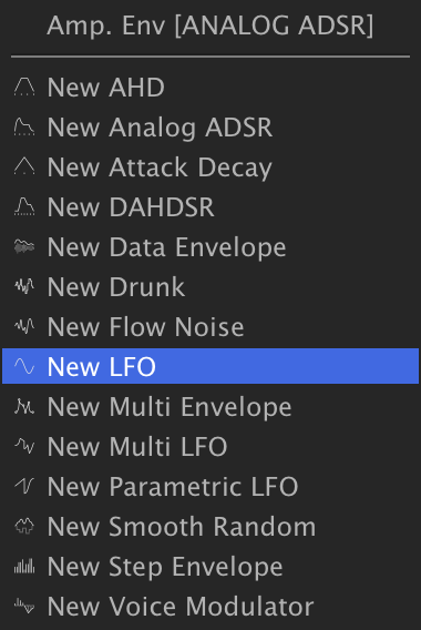
We want to modulate this per voice, so let’s create a keygroup modulation source by choosing INTERNALKEYGROUPNEW LFO.
-
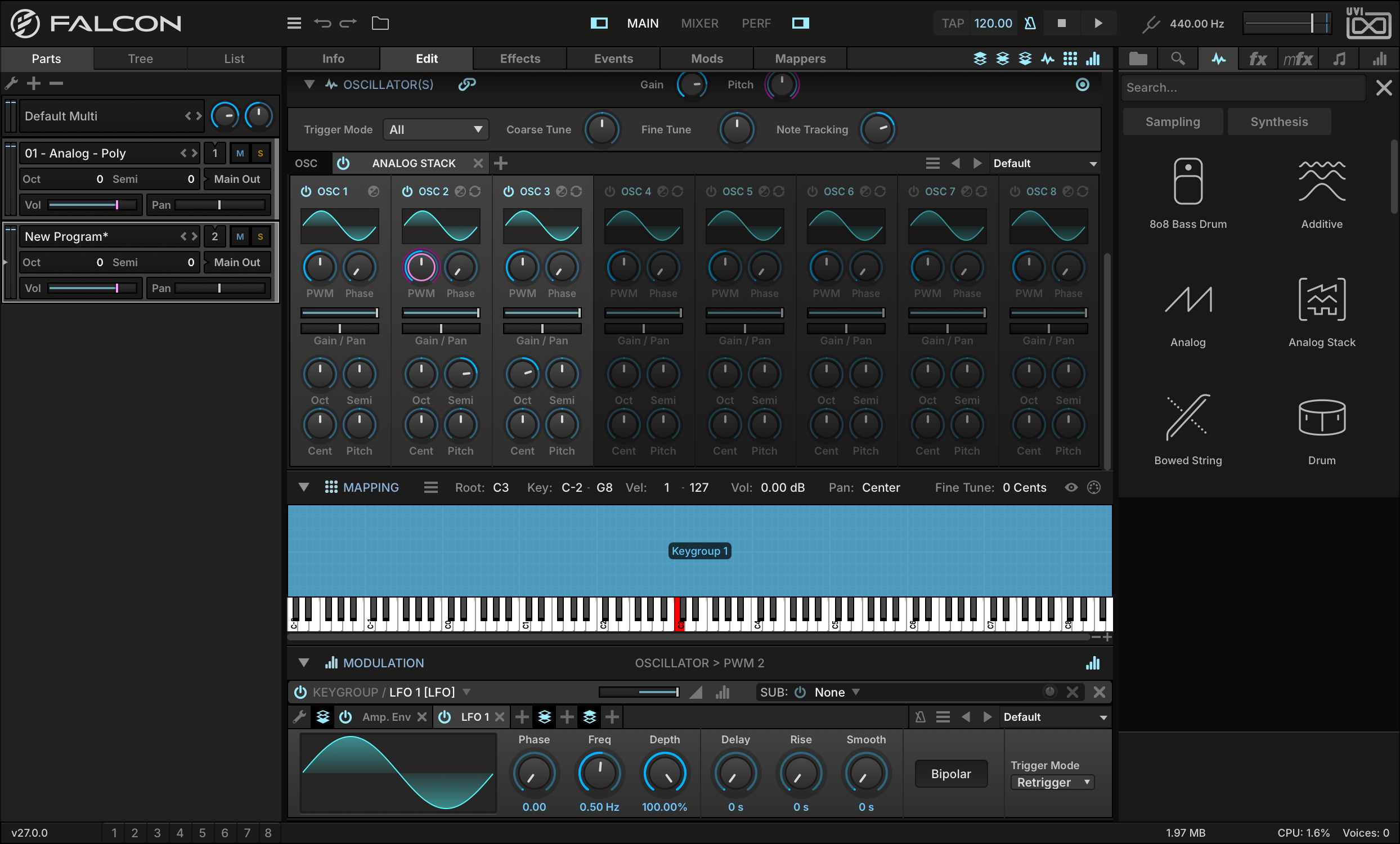
The new modulation source now appears in the MODULATION EDITOR. If you don’t see the Modulation Editor, make sure that its toggle button is enabled at the top of the Edit tab, and that it’s expanded with the arrow next to its name.
-
Play a note and you’ll hear the LFO modulating PWM; this LFO is modulating it too drastically, though, so let’s edit it.
-
Set the RATIO to 0.25, play a note again, and you’ll hear that its intensity has been reduced.

-
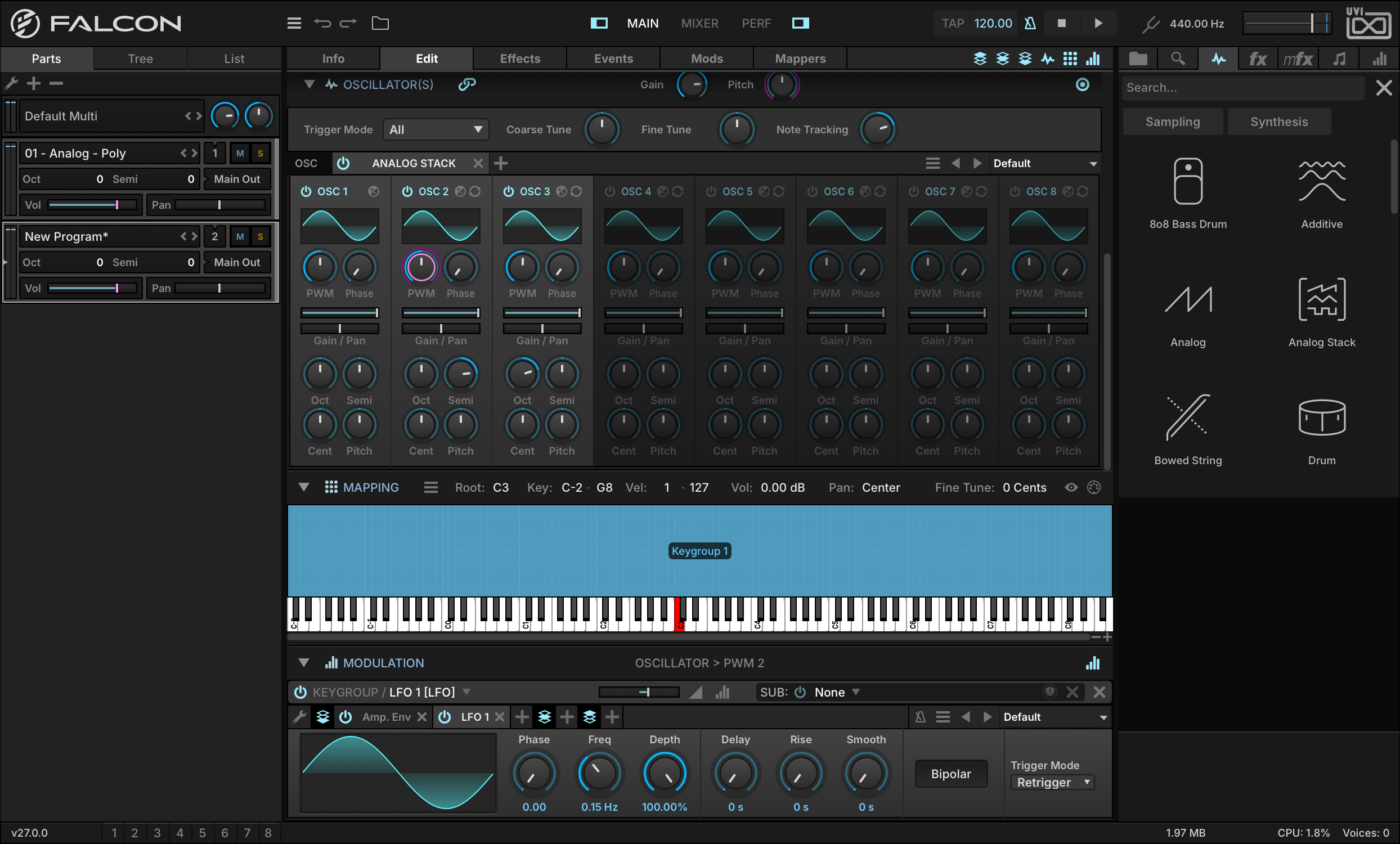
We can also slow the LFO down by setting its FREQ to 0.15 Hz. Let’s do the same with oscillator 3 PWM, but with a different LFO.
-
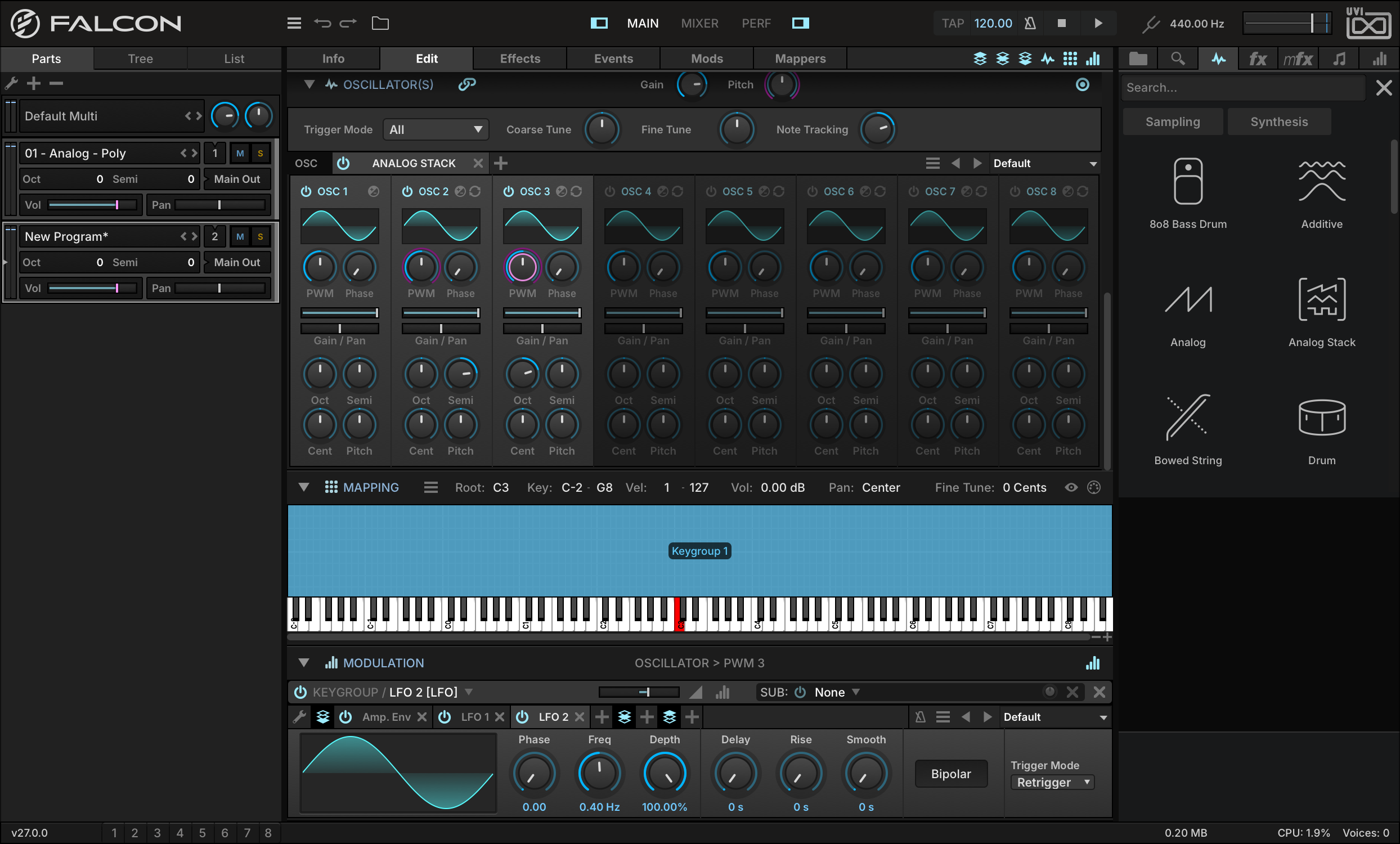
Create another LFO, and set its frequency to be different from the first LFO’s. This will create a sound that shifts and evolves over time. In this way, we can continue to build up the sound by adding modulation to each oscillator’s parameters, such as pan, phase, or pitch.
Make an Interactive Wobble Bass
Falcon’s modulation engine provides endless opportunities for customizing and modifying sounds. Let’s create a wobble bass that we can tweak in real time from our MIDI controller.
-
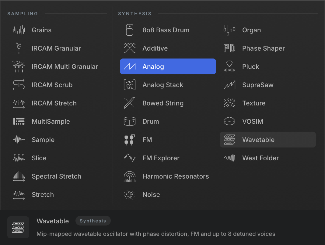
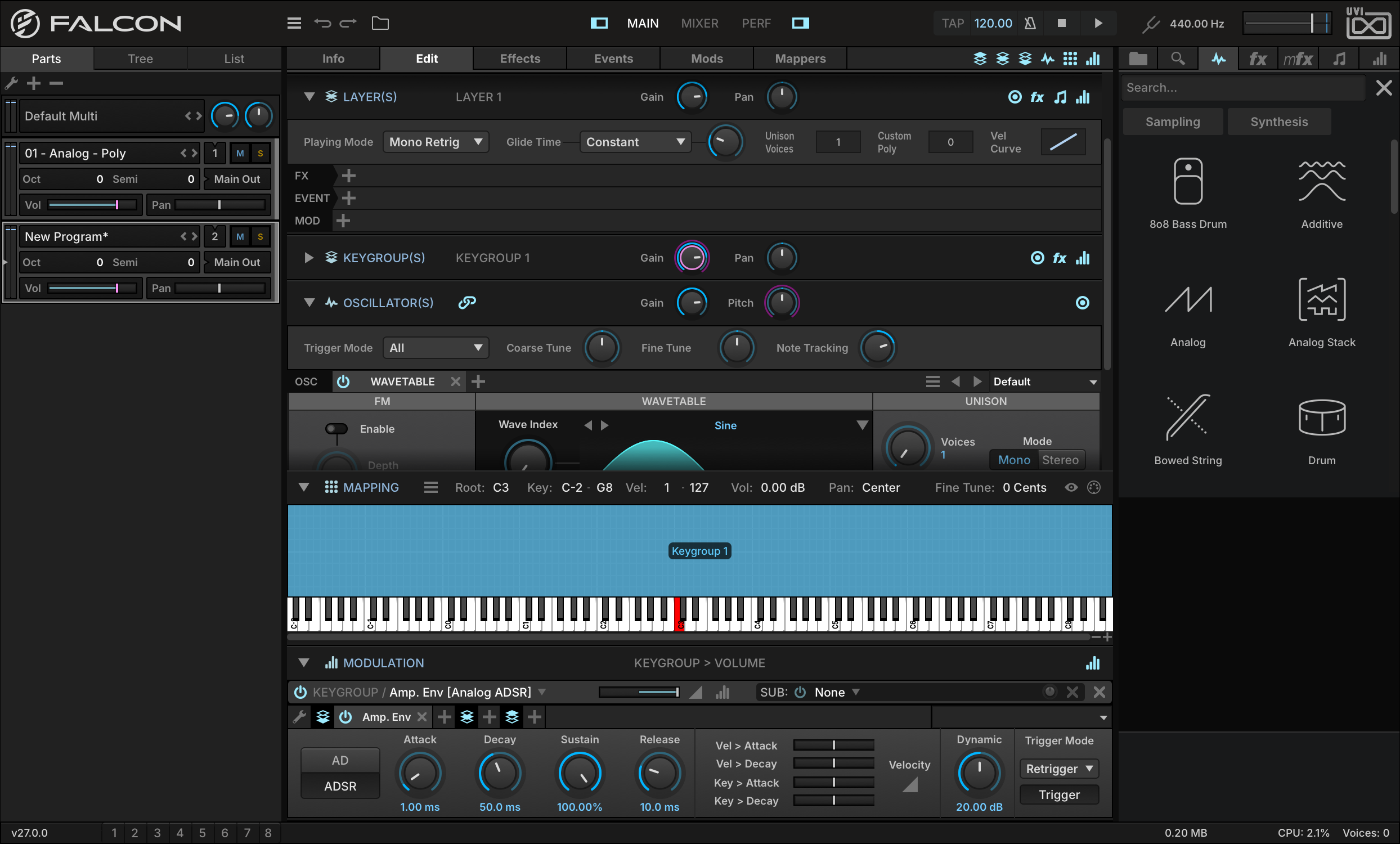
As with the previous examples, start with a clean patch, create a new Synth Template keygroup, then right-click the oscillator name and pick WAVETABLE from the chooser.
-
We also want this sound to be monophonic, so in the Layer section, change the Play Mode from Poly to MONO RETRIGGER.
-
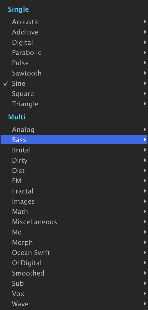
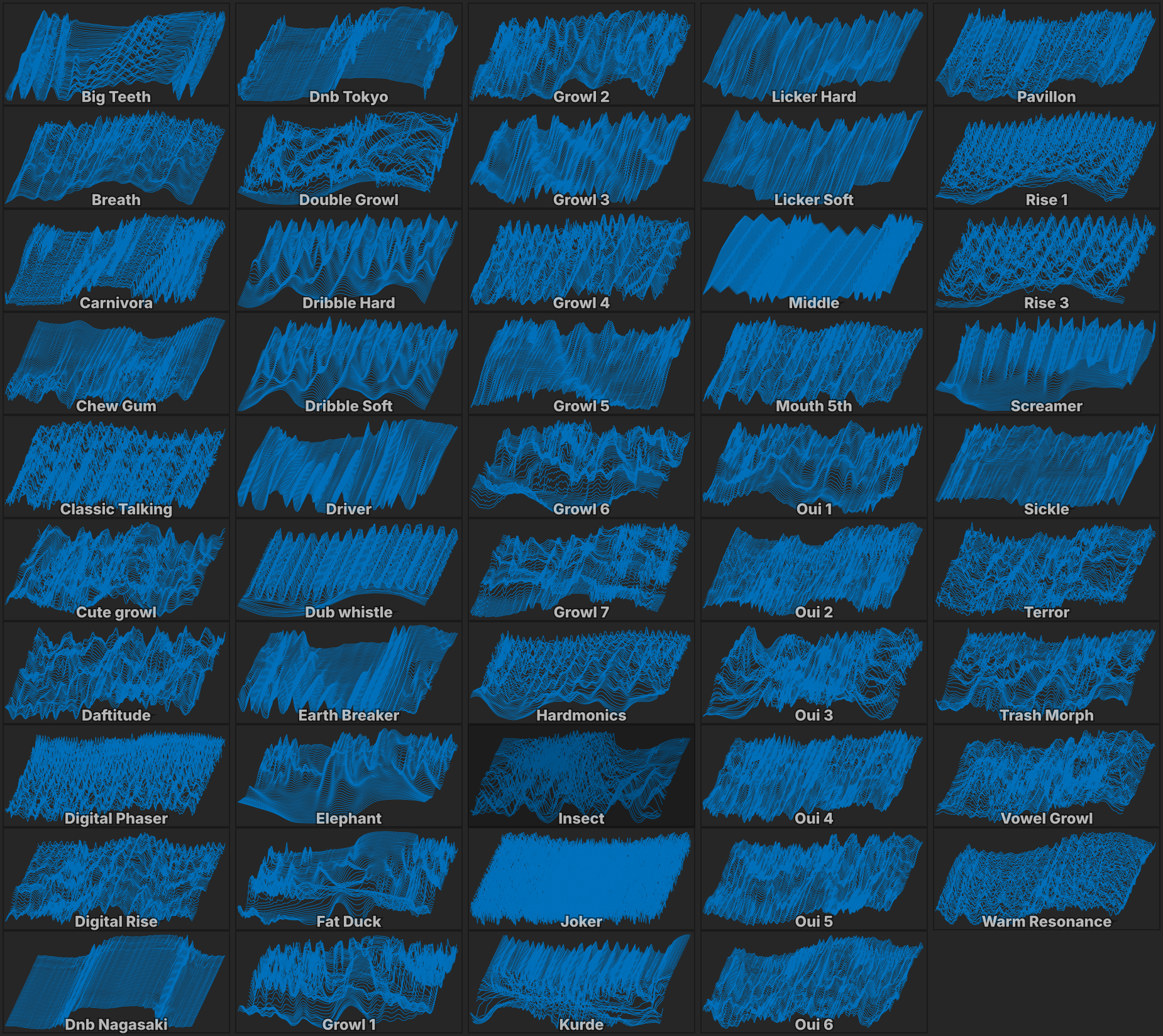
To change the wavetable, press on the menu above the waveform and choose from the menu. Let’s choose MULTIBASSINSECT.
Play and hold a note to audition the wavetable. While holding the note, adjust the WAVE INDEX to change the active waveform within the wavetable. This is a good control to adjust in real time while playing, so let’s assign the Mod Wheel as a modulator.
-
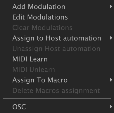
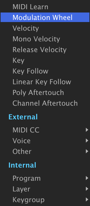
Right-click the Wave Index knob and choose ADD MODULATIONMODULATION WHEEL.
-
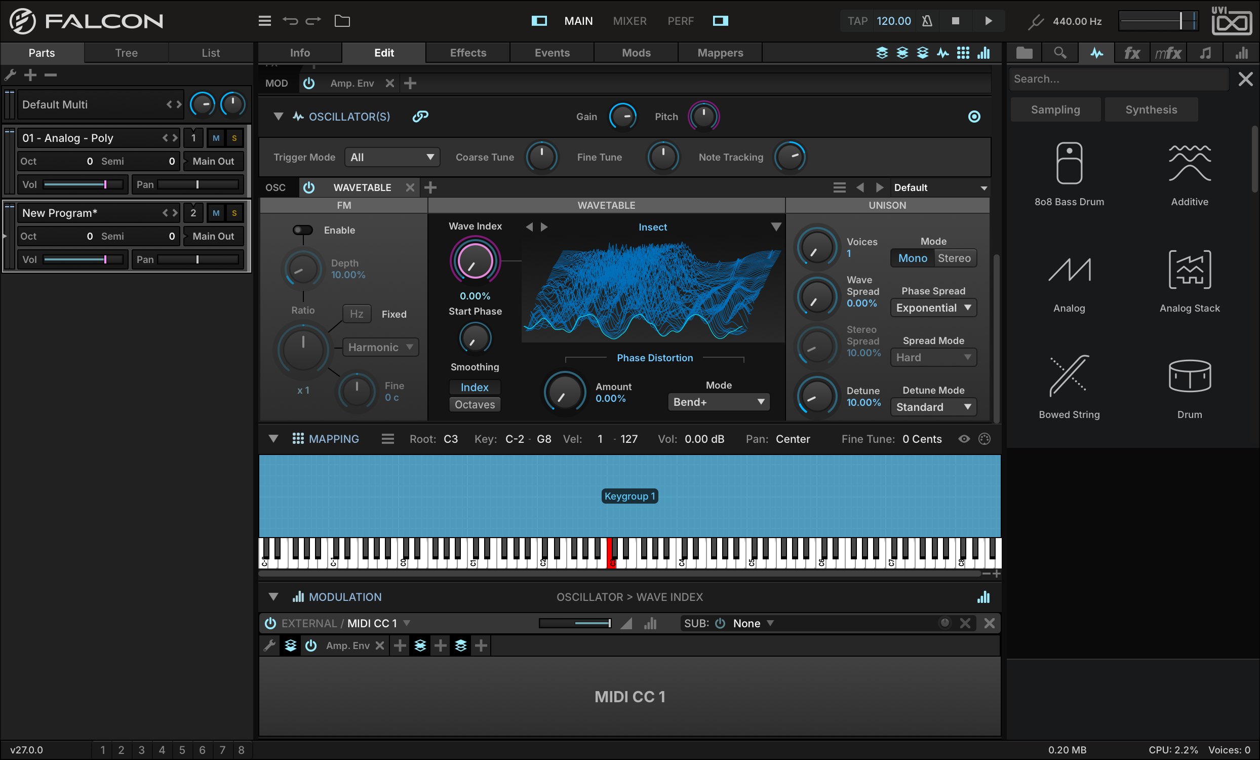
The new modulation assignment now appears in the Modulation Editor. (If you don’t see the Modulation Editor, make sure that its toggle button is enabled at the top of the Edit tab, and that it’s expanded with the arrow next to its name.)
-
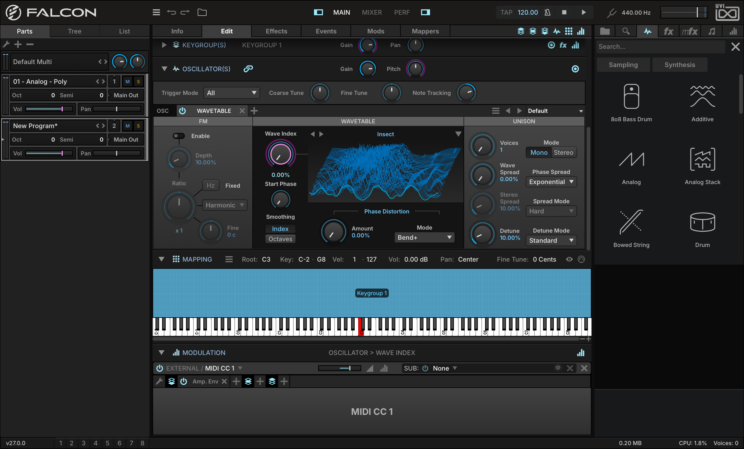
Each modulation assignment has a ratio slider that defines how the modulation source maps to its assigned parameter. By default the full range of the mod wheel will map to the full range of the Wave Index knob, but in this case we’d like the mod wheel to sweep over only half of the Wave Index range. So, to halve the range, set the RATIO of the MIDI CC 1 assignment to 0.5.
-
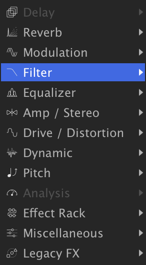
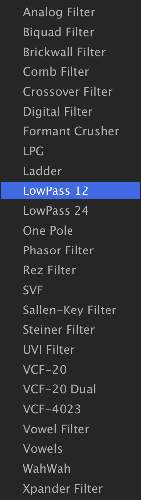
Now let’s add a low-pass filter. To add a filter, go to the keygroup’s Effects lane, press the + button and choose FILTERLOWPASS 12.
-
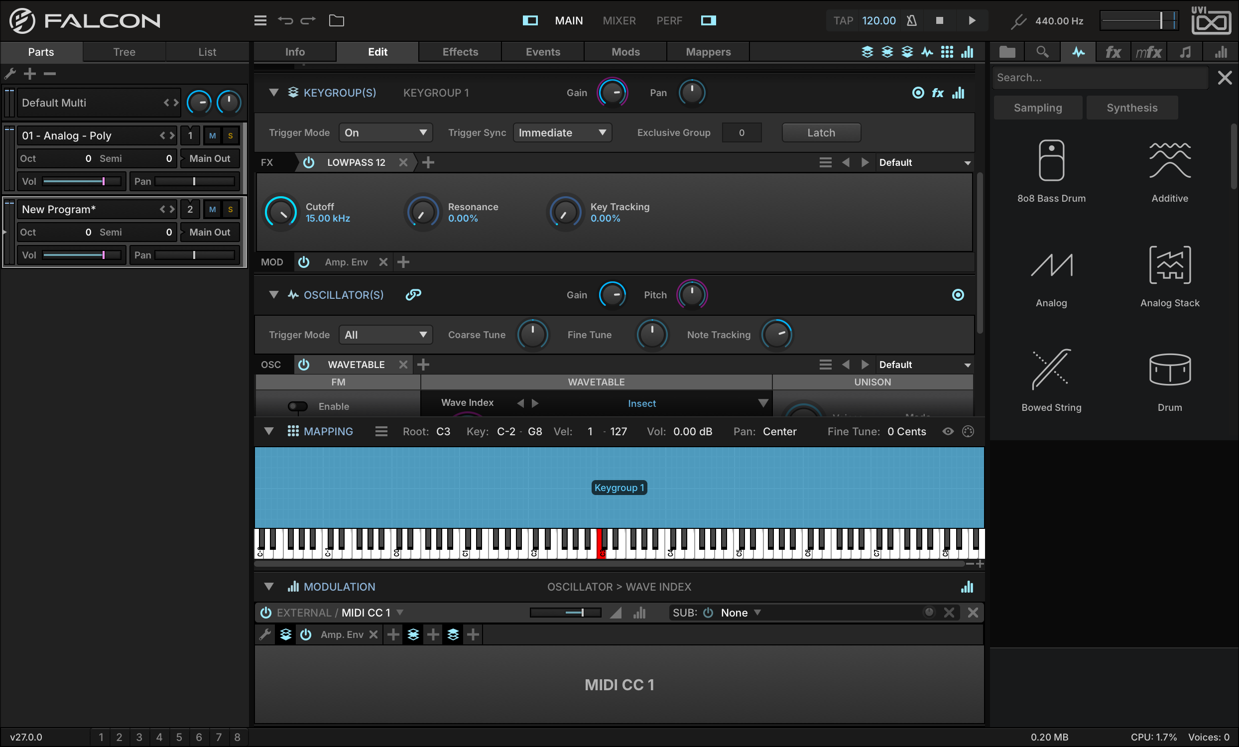
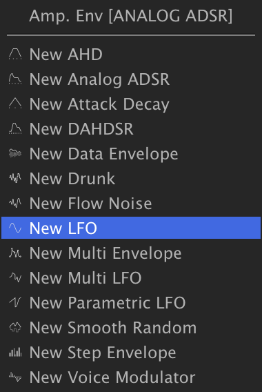
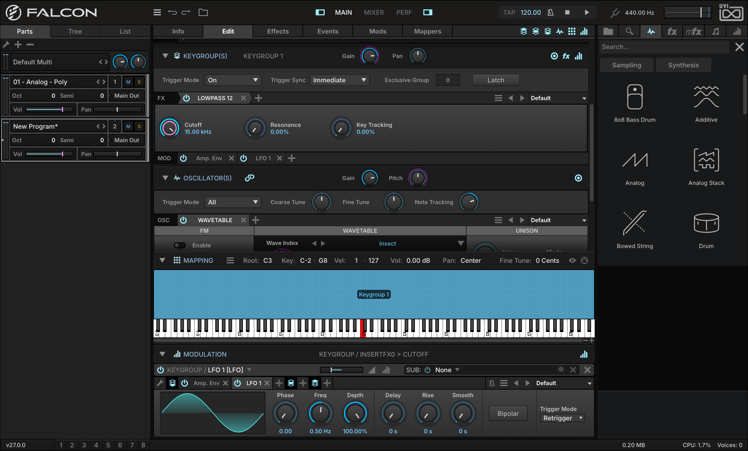
To create the wobbling effect, we can modulate the cutoff frequency with an LFO. Set CUTOFF near the upper end of its range, then right-click, choose ADD MODULATION, and add a new LFO.
-
On the new LFO, uncheck its BIPOLAR option, then set its modulation ratio to −0.5. A unipolar LFO will modulate in only one direction, and a negative ratio means that direction will be downward.
-
Play a note, and you’ll hear the cutoff frequency sweeping downward with the LFO. The LFO is applied as a constant modulation, however. To apply the LFO modulation selectively with the modulation wheel, add the mod wheel as a sub-modulation source. Right-click on the SUB menu and choose MODULATION WHEEL.
Play a note now, and you won’t hear the LFO applied any more. As you raise the mod wheel, the LFO modulation will be increasingly applied, along with the Wave Index modulation we assigned to the mod wheel earlier.
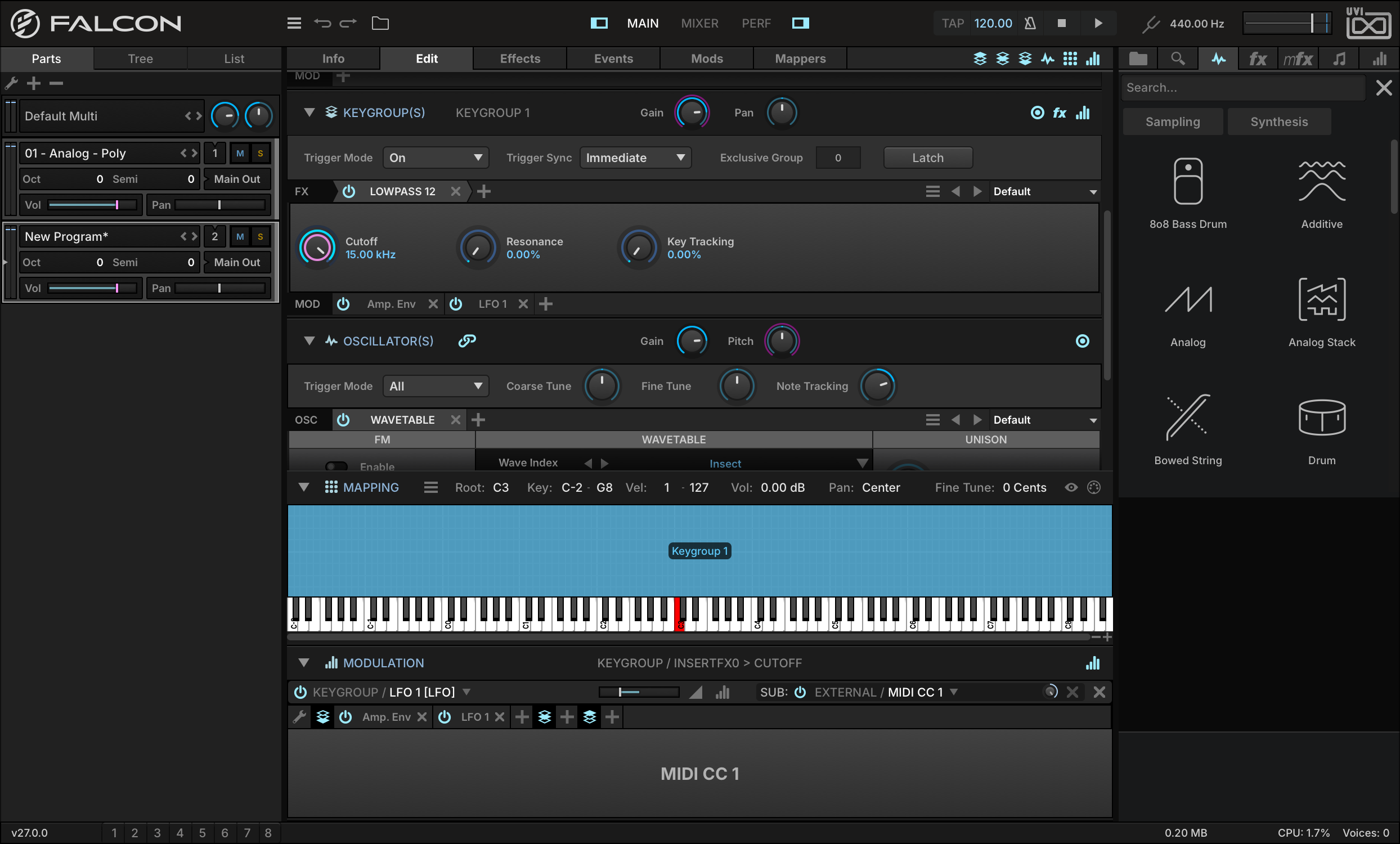
Make a Drum Kit from Samples
Creating new programs from samples is just as easy as creating a synth-based program. Most of Falcon’s controls are used in the same way whether you’re using synth oscillators or sample files. Let’s create a drum kit from sample files.
-
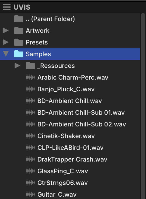
Open the right-hand sidebar and use the FILES tab to locate a folder containing some drum samples on your system.
-
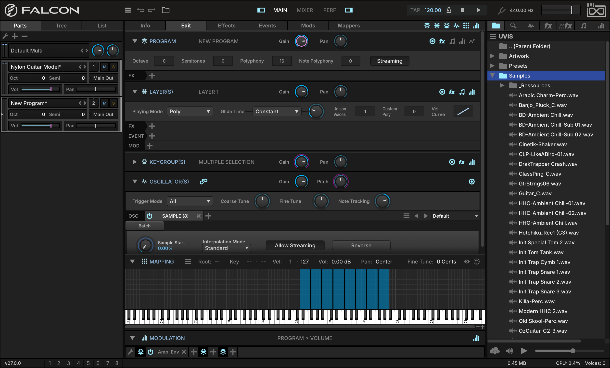
Select the drum samples you want to use (Shift-click to select several) and drag them onto the MAPPING EDITOR.
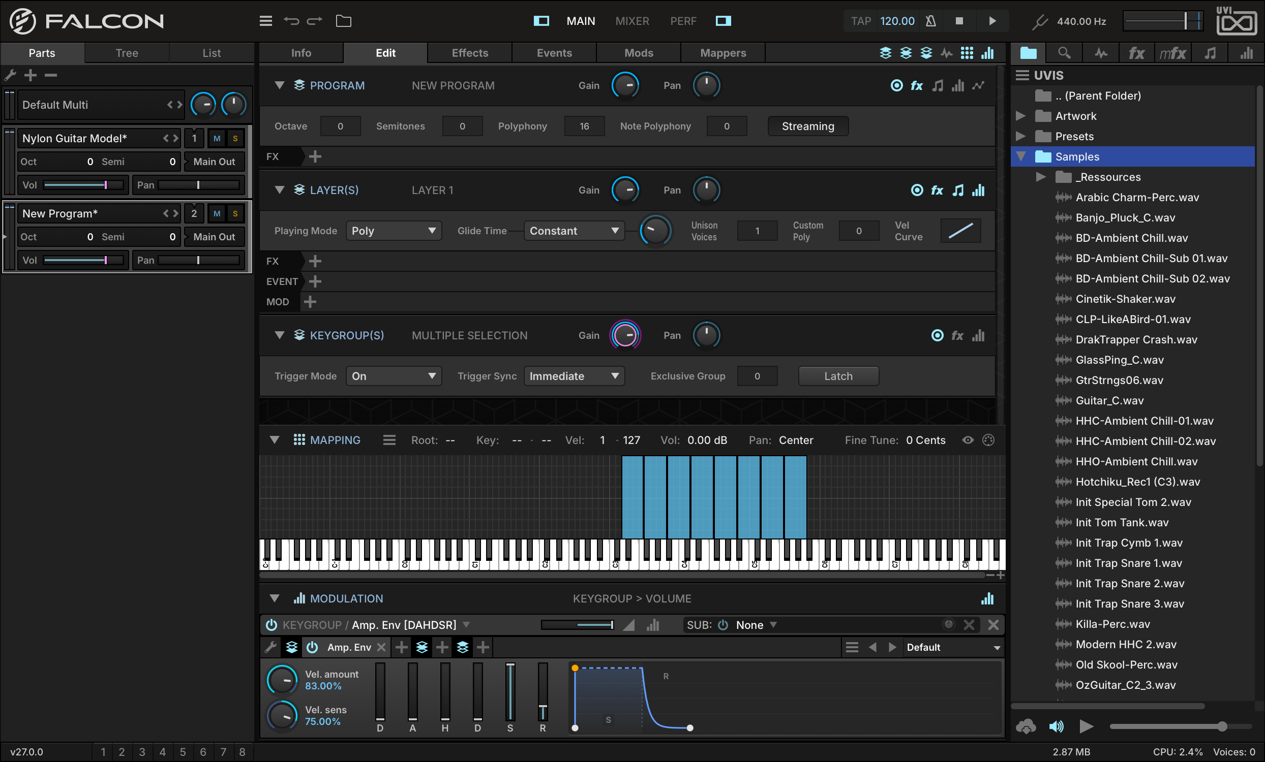
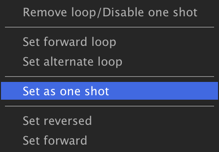
Now let’s set the imported samples to be “one shot” samples, so that the entire sample will be played back when the note is triggered.
-
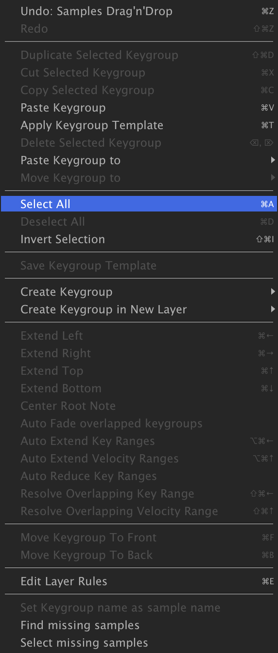
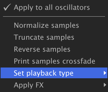
Choose SELECT ALL from the Mapping Editor menu, then press the BATCH button and choose SET PLAYBACK TYPESET AS ONE SHOT.
-
-
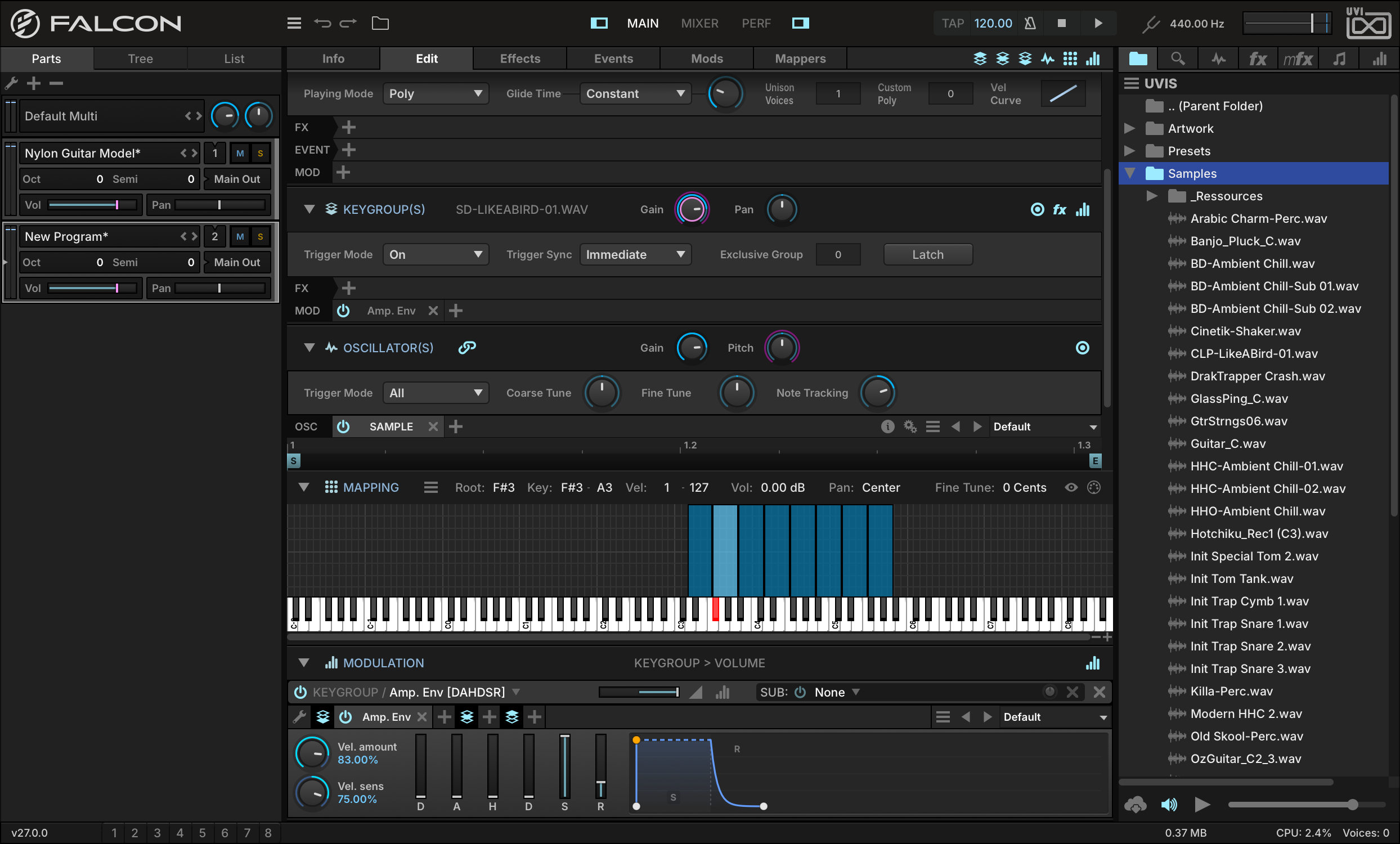
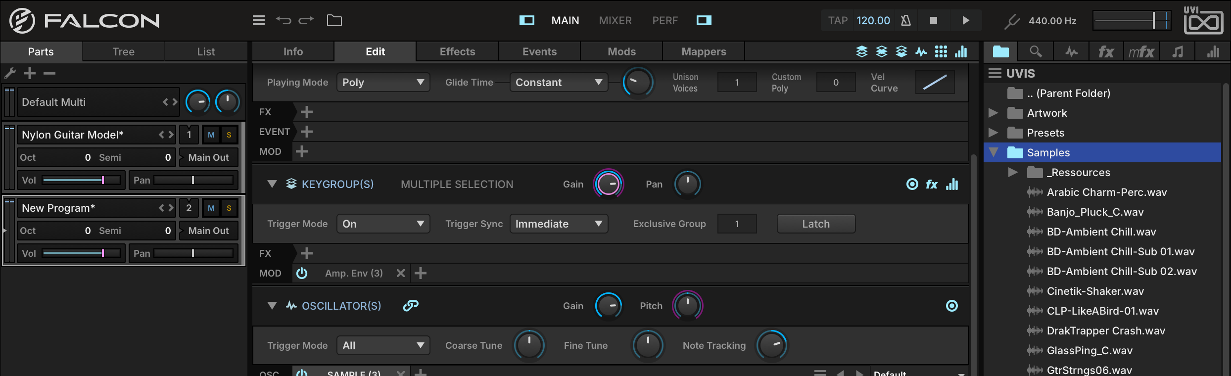
Lastly, let’s set an exclusive group for the hi-hat sounds. This will mimic the natural behavior of hi-hat sounds cutting each other off, such as a hi-hat closing and cutting off a ringing open hi-hat.
Select the hi-hat keygroups, then set EXCLUSIVE GROUP to 1 in the Keygroup section.
Make a Drum Kit from a Loop
Drum loops often provide great source material for building a drum kit, especially if the loop has distinct hits where the different kit elements don’t overlap. By slicing and mapping the hits in the loop, we can easily take a single loop and turn it into a full kit.
-
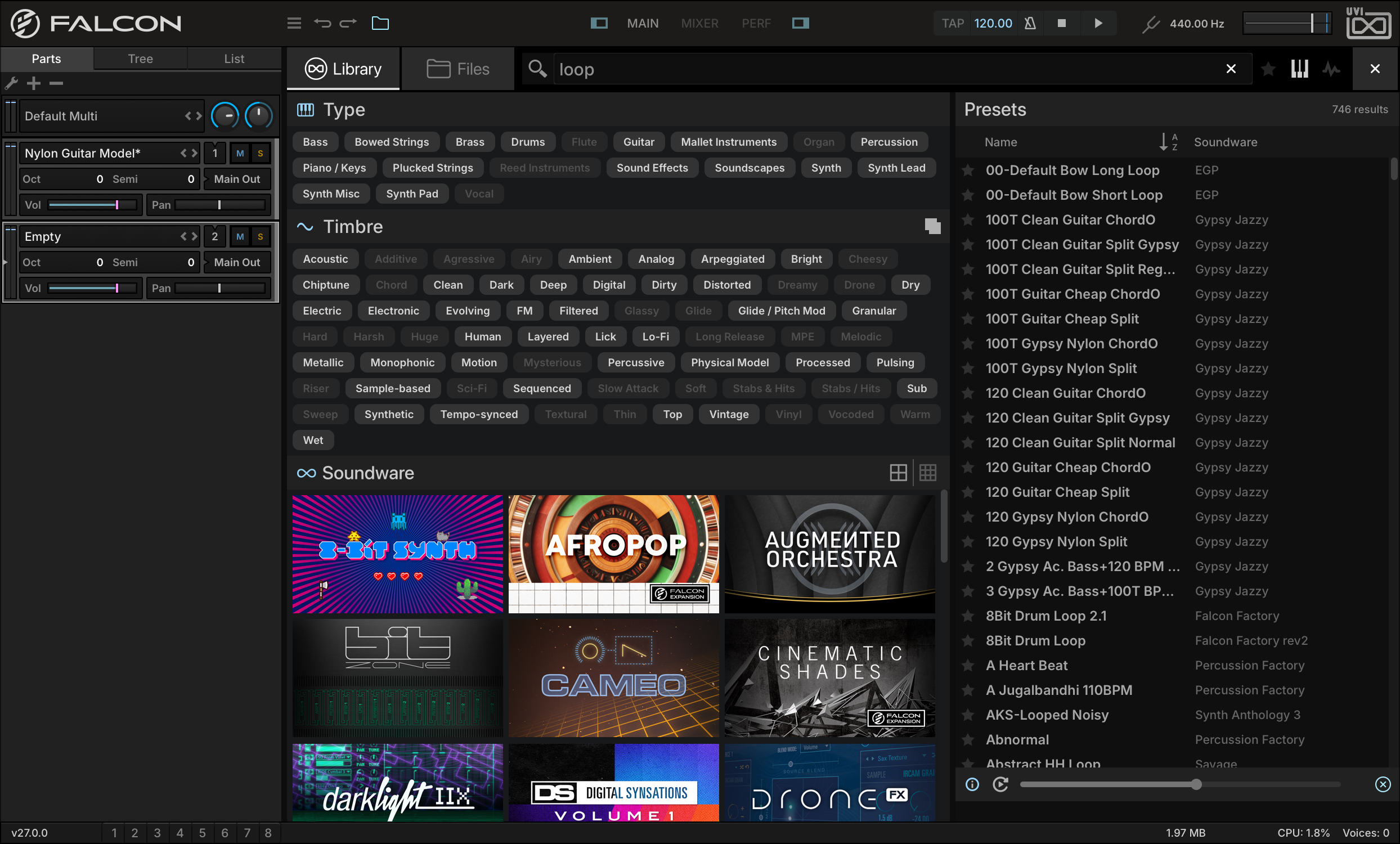
Let’s start by loading a drum loop into an empty part. In this case we use the Library Browser to find a loop from our Mayhem of Loops Soundware and double-click to load it. If Mayhem of Loops is not available for you, choose a loop from your Soundware, such as BeatBox Anthology 2 or Toy Museum or your own loop libraries.
-
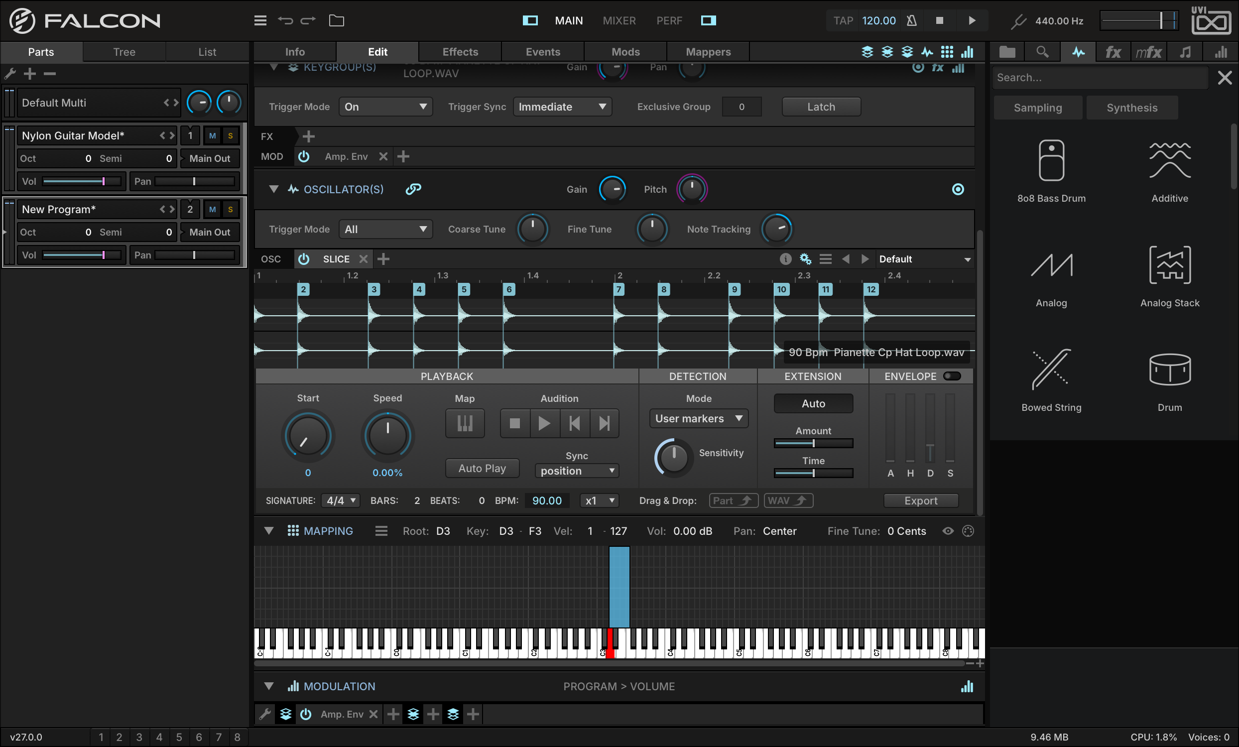
You’ll see that the sample is loaded within the SLICE oscillator, with slices marked at each transient. Press Play in Falcon, and the slices are played back in sync with Falcon’s tempo.
-
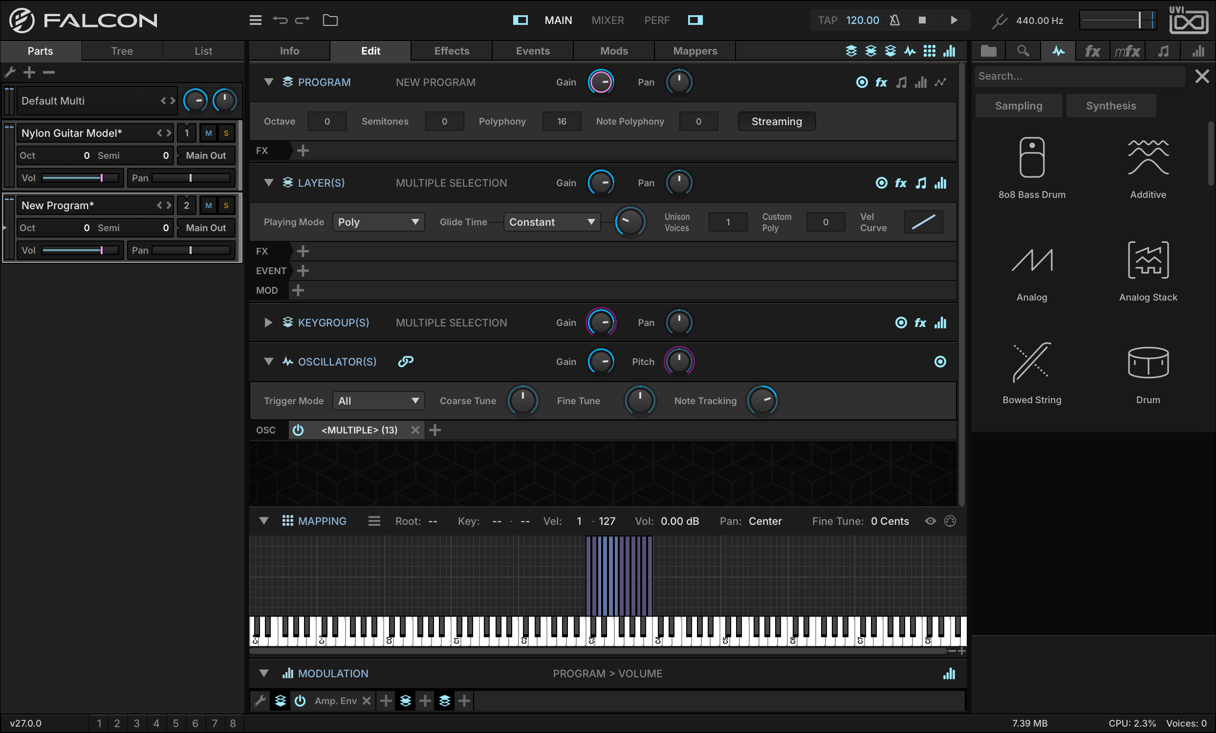
You can convert these slices to separate keygroups, so that each slice can be triggered independently. Press the MAP button, and a new layer will be created with the slices mapped to individual keys.
-
The original keygroup containing the loop will still be present in a muted layer. To hide it, open the TREE view and select only the MAPPED layer.
Play a few notes on your keyboard to trigger the new sliced keygroups. You can now easily rearrange the slices to the mapping of your choice, such as a standard drum mapping.
Each slice from the mapped loop is actually referring back to the original sample, with custom start and end markers to define the slice within the larger sample.
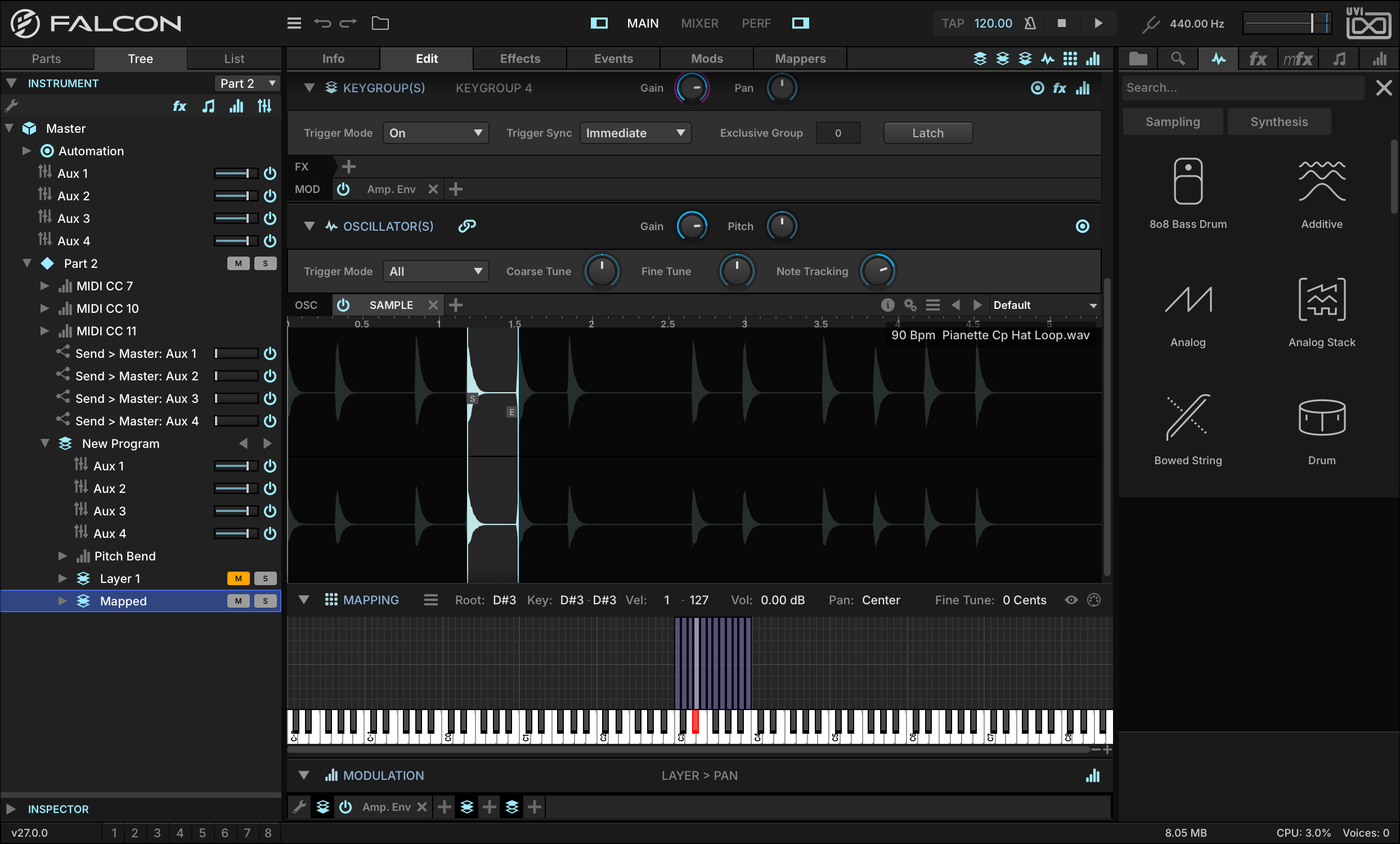
-
To adjust the slice boundaries, select a keygroup to show its Sample oscillator, then drag the S (start) or E (end) marker as desired.
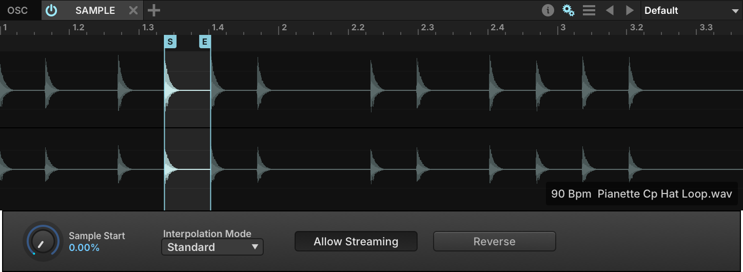
-
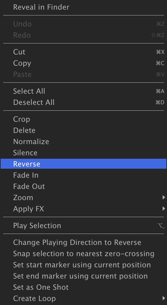
Double-click the sample waveform between the start and end markers to select it. From here you can right-click to reveal a number of common wave editor commands such as reverse, normalize, fade in/out and silence. Changes made here still reference the original file, so they affect all slices — and saving the sample overwrites that original file, so take care. With MIDI SELECT enabled in the Mapping Editor toolbar, the waveform of the keygroup you play is shown.
Slices can be tweaked and tuned in limitless ways. Try changing the sample oscillator type to Stretch and adjusting the Tempo Factor, or adding effects to a specific keygroup to affect only one slice, or at the layer level to affect them all.
Make a Drum Kit with Synthesis
Instead of starting with a looped sample or a collection of sampled drum hits, we can also create entirely new drum sounds from scratch with Falcon’s Drum synth oscillator.
-
Open the right-hand sidebar and choose the OSC tab. Press SYNTHESIS and expand DRUM in the tree: all of the drum synth oscillator presets are listed under it, in the folder each one belongs to.
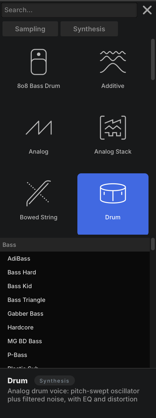
-
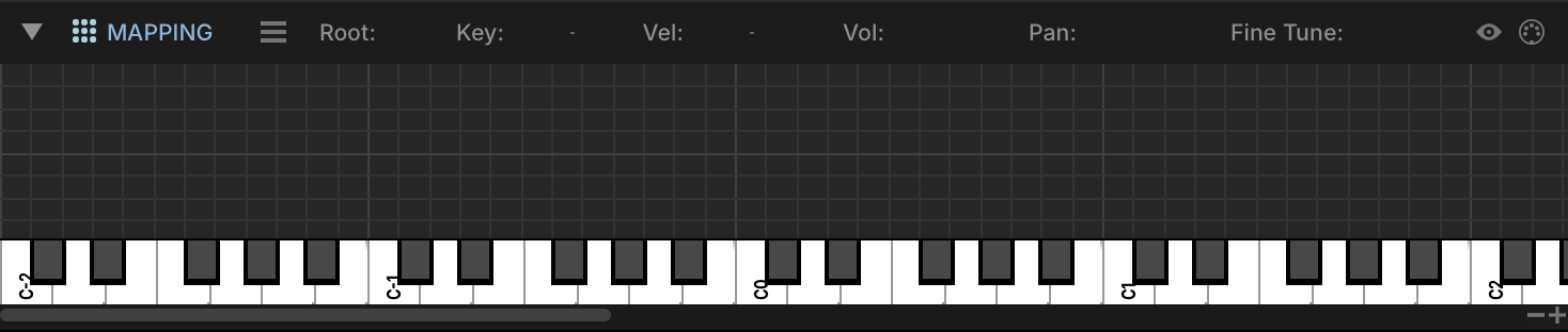
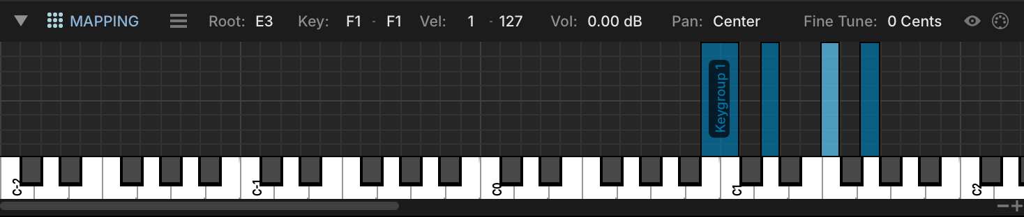
Before we get started, zoom in a bit in the MAPPING EDITOR to see the key range we’re going to focus on in greater detail. Click the + button on the bottom right of the editor to zoom in; drag the border between the Mapping Editor toolbar and the editor to give the velocity range more room.
-
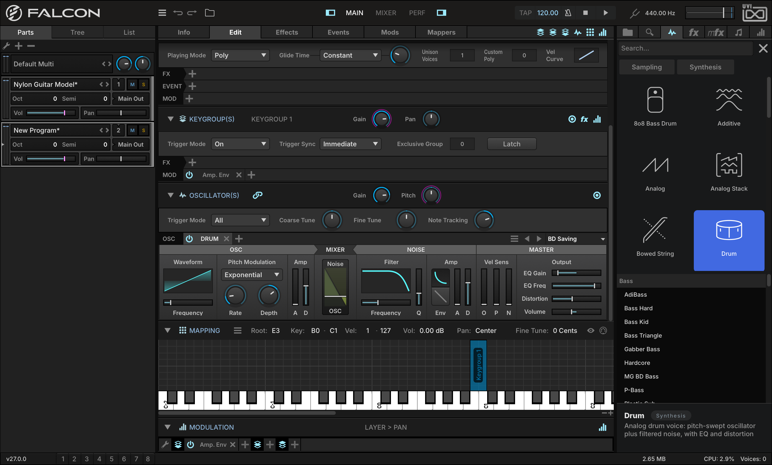
Let’s start by adding the BD preset BD SAVING to cover the range B0 to C1. As you drag and drop, the vertical position within the Mapping Editor determines the key range of the keygroup, with wider ranges set near the top and narrower ranges near the bottom.
The Drum oscillator consists of two sound generators, a pitched oscillator and a noise generator. The two can be independently edited, then the mix between the two is set with the Mixer. The Master section adjusts the combined signal, with EQ, distortion, and other settings.
-
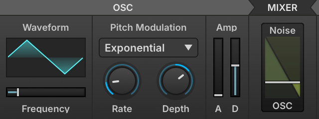
To give the kick a little more edge, let’s change the Oscillator waveform from sine to TRIANGLE, and move the OSC/NOISE slider to add a little noise.
-
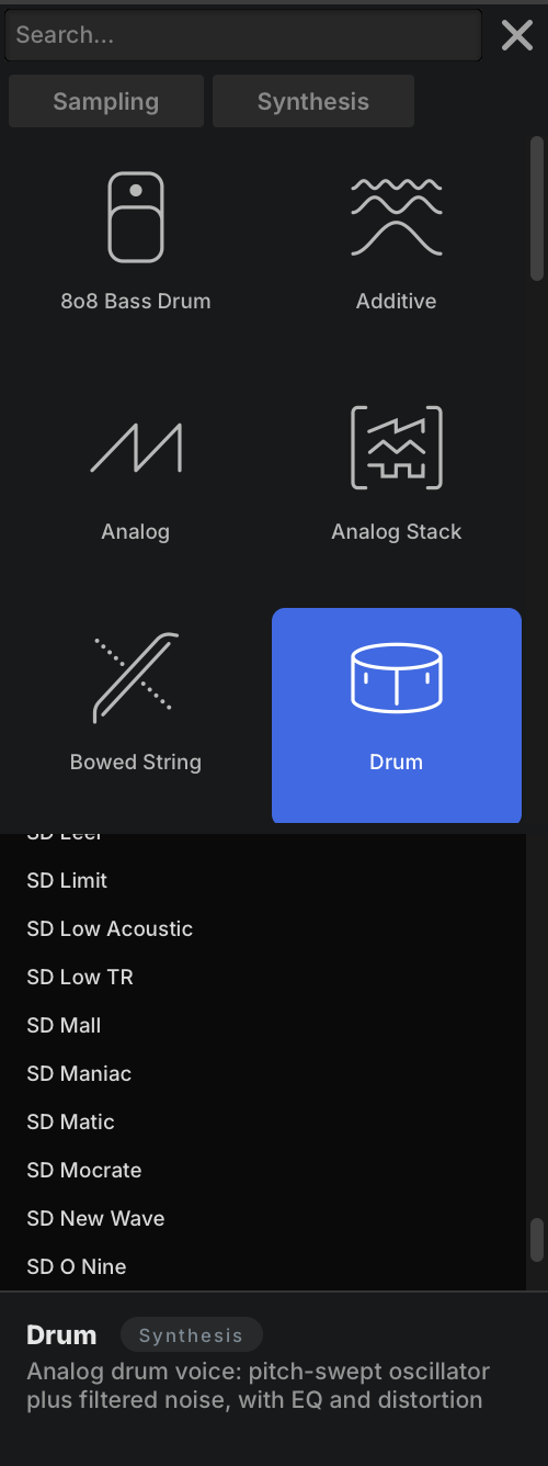
Now let’s import the SD MANIAC preset from the SD folder to D1, and play a few notes to see how the kick and snare sound. Let’s bump up the DISTORTION, and lower the Q on the noise filter.
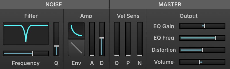
-
For toms, let’s drag over a preset from the Electric Tom folder, LARGE TOM, to F1.
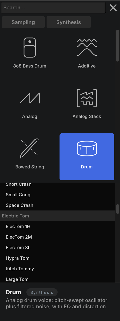
-
We can then tune the tom with the oscillator’s FREQUENCY slider.
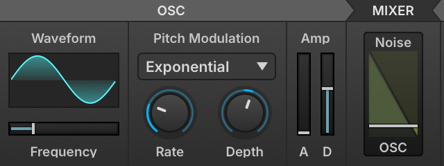
-
To use this customized tom as the starting point for additional toms, right-click the keygroup and choose DUPLICATE SELECTED KEYGROUP.
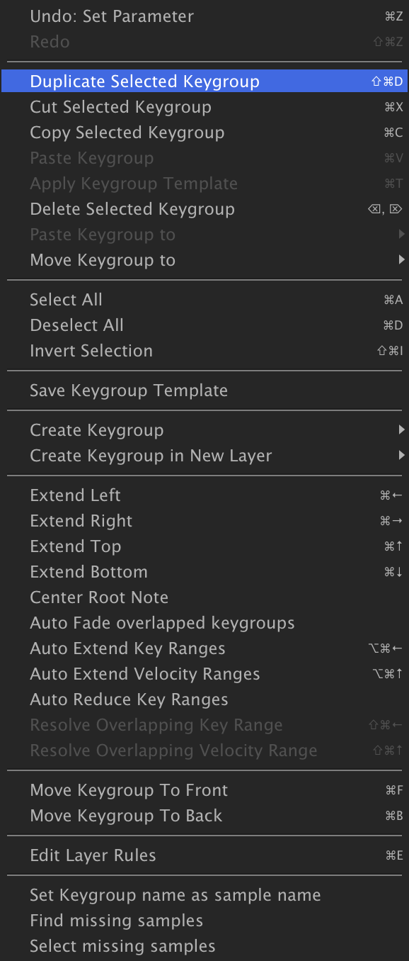
-
The duplicated keygroup will initially appear stacked on top of the existing one; grab the new keygroup and drag it over to G1, then adjust its frequency to change the tom’s pitch.
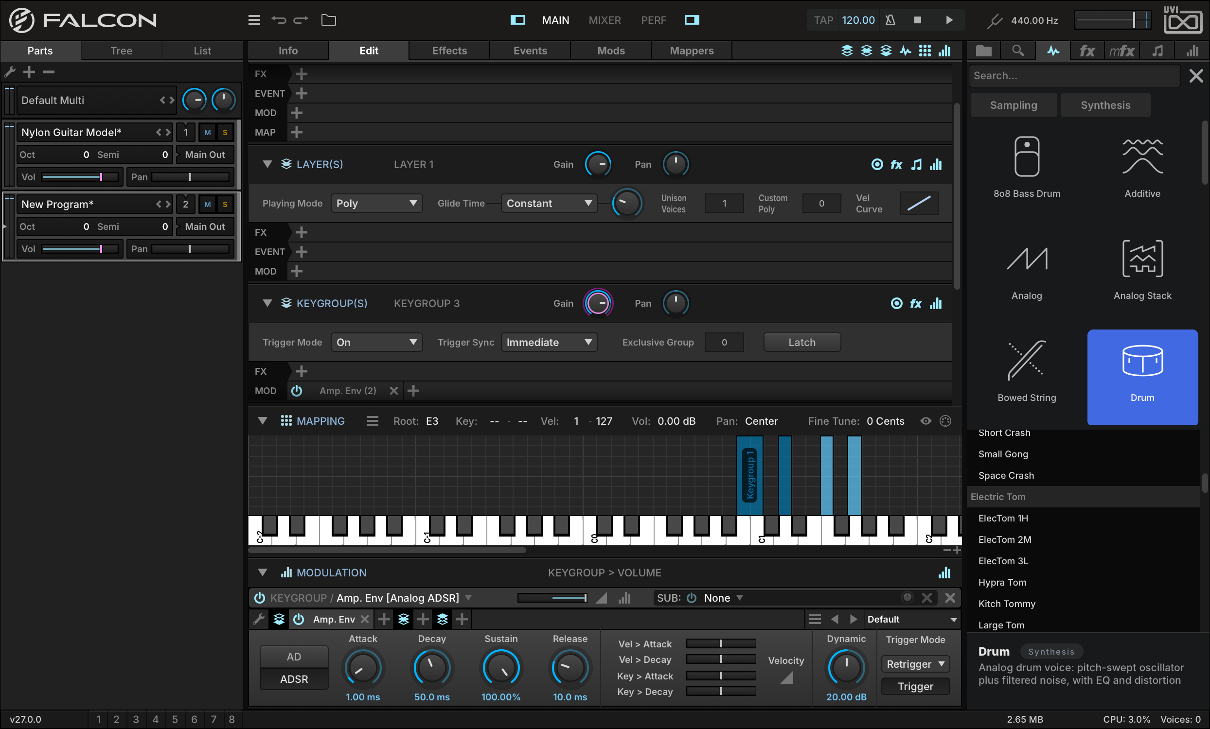
To change the length of time the toms ring out, let’s tweak their amplitude envelope. If it’s not already displayed, toggle visibility of the Modulation Editor with its button in the upper right of the Edit tab.
-
Click and drag a selection over the tom keygroups, then click the AMP. ENV tab in the MODULATION EDITOR. When you adjust the envelope’s RELEASE knob, you’ll be editing the release time for all of the selected keygroups.
-
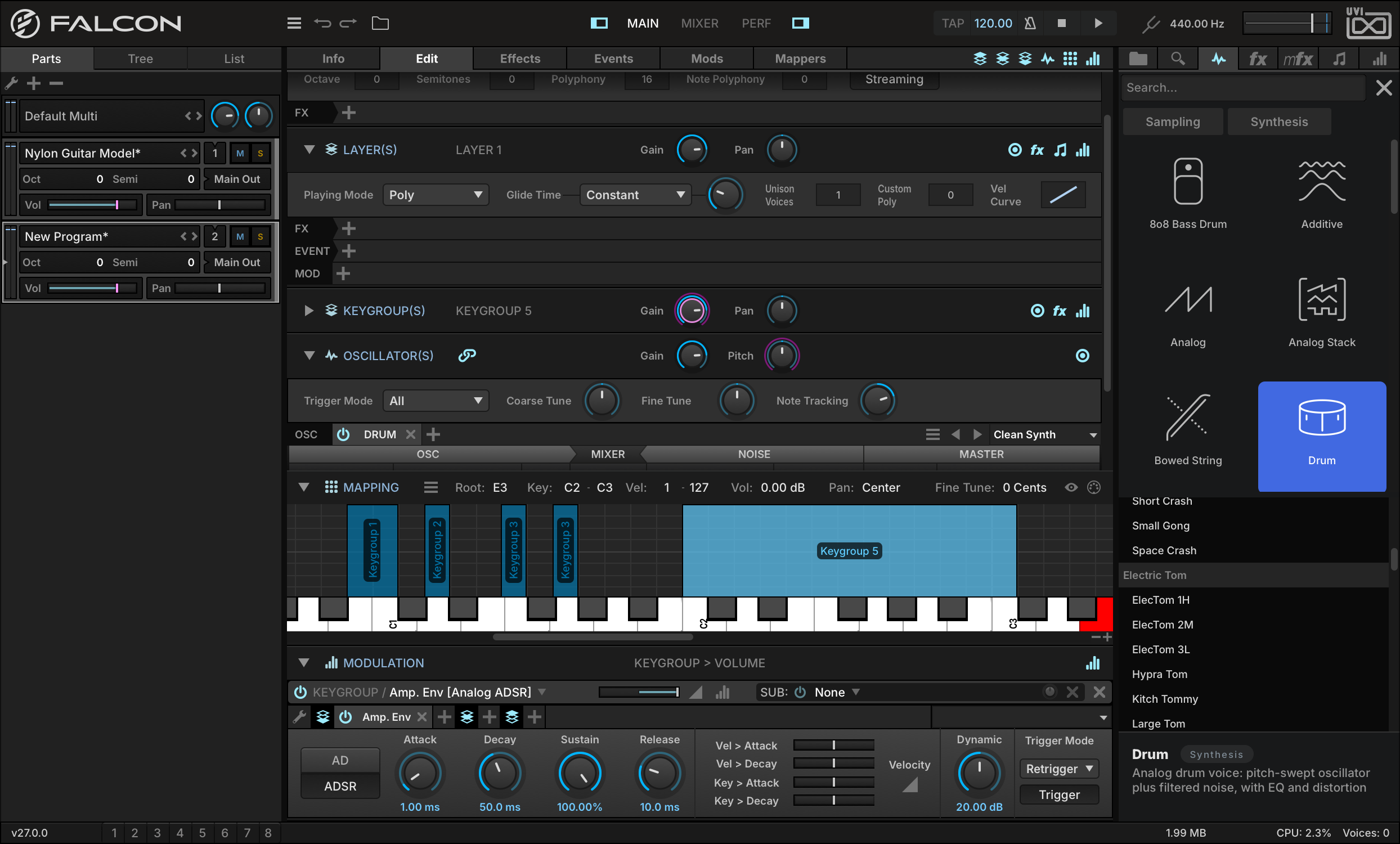
We can also use the Drum oscillator for synth lead or bass sounds. For example, drag in a preset from the Synth folder, such as CLEAN SYNTH, to cover the range C2 to C3. Moving this keygroup to a separate layer will give us more flexibility with effects routing and other program settings, so let’s move the keygroup.
-
Right-click the synth keygroup in the Mapping Editor and choose MOVE KEYGROUP TONEW LAYER.
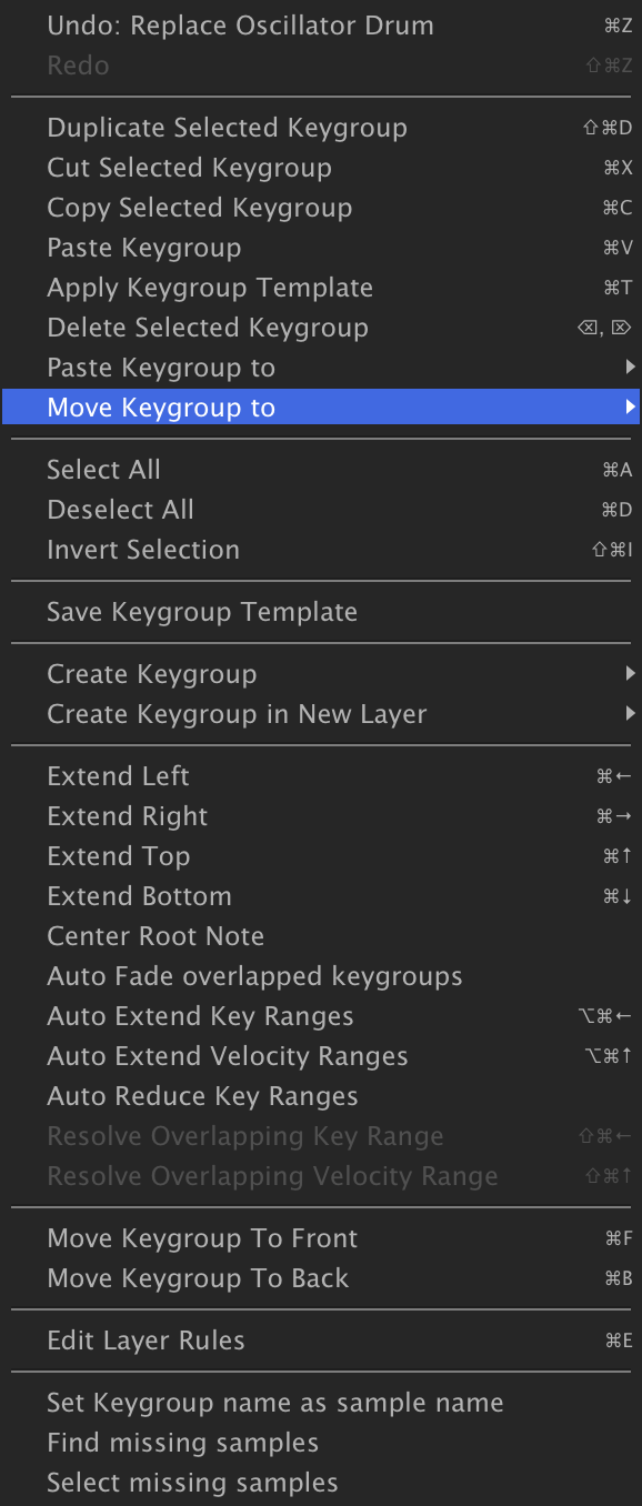

You now have a drum kit built from Drum oscillator presets, with a synth on a layer of its own that can take its own effects (see Interface › Effects); for every Drum control, see Oscillators › Drum.
Learning: Effects, Modulation + Automation
Effects + Modulation
Falcon has an extensive selection of audio effects and modulation sources that can be configured in both simple and extremely complex ways to achieve powerful effects. Most of these modules work on the same principles and interactions.
If you’ve followed the examples in the previous lessons, you should already be familiar with the basic concepts and use of effects and modulators in Falcon. Here we’ll build on that experience and explore some ways to further enhance your ability to both design sound and get hands-on with your patches.
For a detailed overview of each effect module and modulation source, please consult Effects and Modulators.
Using Dual Delay X
Dual Delay X is a delay effects module that is capable of a wide range of time-based effects, from classic delays to reverb-like decays to more unusual effects, with an immersive interface to visualize the stereo and phase adjustments being made.
-
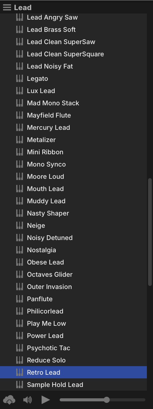
Let’s start with a preset from the FALCON FACTORY REV2 Soundware: in LEAD, find and double-click RETRO LEAD to load it.
-
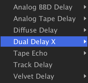
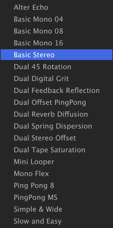
Switch to the EFFECTS tab, right-click the Analog Tape Delay effect header and choose DELAYDUAL DELAY X01 CLASSICBASIC STEREO.
-
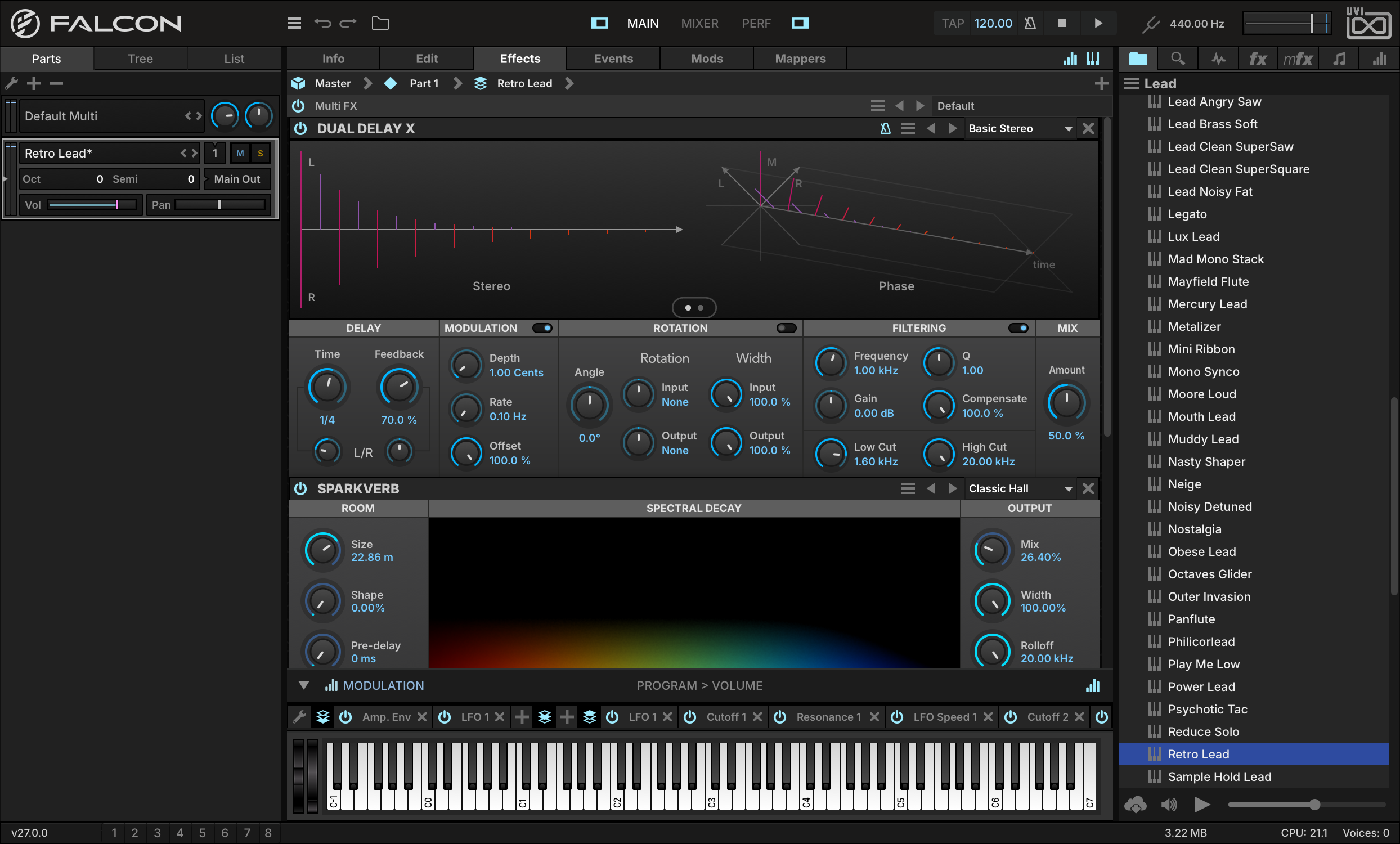
First, let’s increase DELAYTIME to 1/4 for a more pronounced delay effect. The delay time can be specified in milliseconds, or in bars/beats if tempo sync is enabled (as it is here).
-
The Stereo and Phase graphs are the centerpiece of the Dual Delay X interface. As you adjust the parameters below, the graphs are updated in real time. Let’s turn the DELAYFEEDBACK knob up to 70 %: you will see both the number of delay taps and their magnitude increase.
-
Time and Feedback can be the same for the left and right channels, or one channel can be shifted relative to the other. Turn the L/R knob under TIME counter-clockwise until it reads L x 0.50, and you will see the left channel delay taps are half the duration of the right channel delay taps.
-
Let’s add some gentle pitch modulation to our sound to give it a chorusing effect. Set MODULATIONDEPTH to 1.00 cents and MODULATIONRATE to 0.1 Hz.
-
Now let’s adjust the filter to clean up the low-frequency content: set FILTERINGLOW CUT to 1.6 kHz.
-
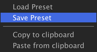
Once you have the effect where you like it, you can save its state as a preset. In the upper right of the effect module, press the Preset File menu and choose SAVE PRESET, and enter a name for the preset. Here we’ll name it MY PRESET.
-
You’ll now see your custom preset in the FX tab of the right sidebar and in the module’s preset menu, within a User Preset folder alongside the factory presets for the module.
Dual Delay X can produce many classic effects through its time and phase settings. A short delay time with modulation, for example, gives a chorus or flanger, with the modulation, filter and rotation parameters shaping its character — and it can also create sounds you have never heard before. The factory presets in the 08 CREATIVE category give many examples of special effects to explore.
Using SparkVerb
SparkVerb is a unique and versatile reverb with an extraordinarily light CPU footprint, whose frequency-based spectral display shows the decay band by band. A single Size parameter emulates room reflections from 4 m to 50 m while Decay can be shaped globally and with independent low and high frequency multipliers, each with adjustable crossovers.
-
Let’s create a quick set of loops. In this case we’re using Falcon’s search engine to find loops across our Soundware such as Mayhem of Loops. Navigate to it and create new parts for loop files by dragging them over to the parts list. If the loops aren’t playing automatically, press Play in Falcon’s toolbar or in your DAW’s transport if you’re using Falcon as a plug-in.
-
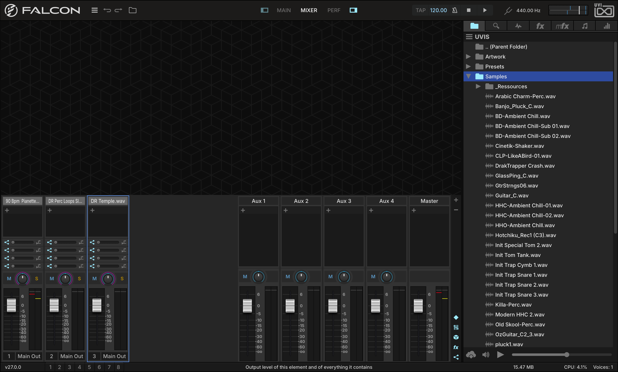
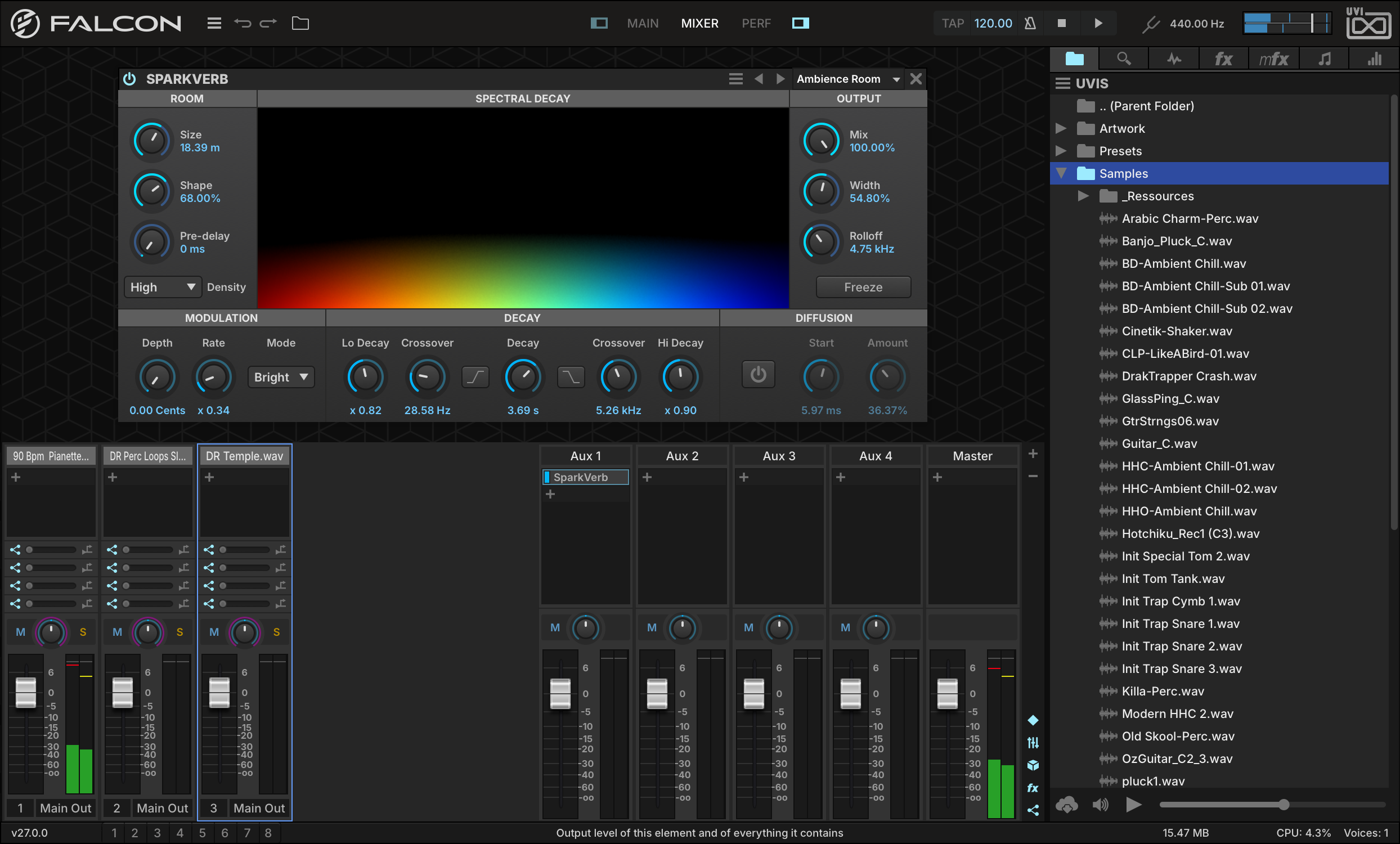
Now that we have some loops let’s put SparkVerb on an Aux channel. This will allow us to use one instance of SparkVerb for as many parts as we like. Click the MIXER button in Falcon’s toolbar to change the current view. Now we can see our 3 instrument parts on the left and 4 aux channels and the master on the right.
-
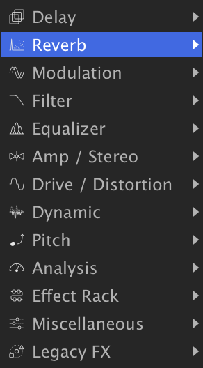
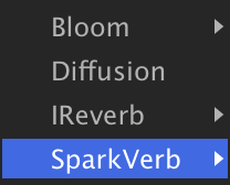
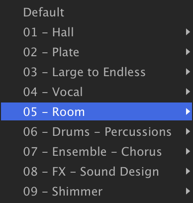
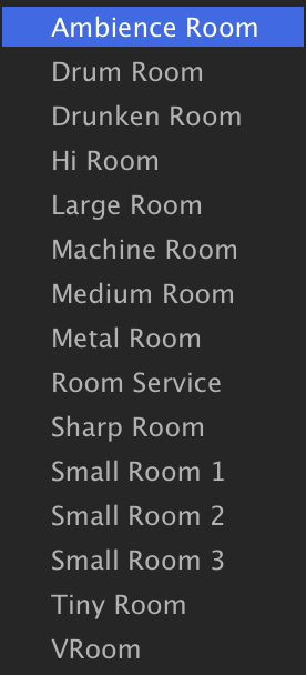
Click the + button at the top of the AUX1 channel and select REVERBSPARKVERB05 - ROOMAMBIENCE ROOM. You should now see the SparkVerb interface at the top.
-
At the center of the SparkVerb interface is the spectral display. Frequency is mapped across the X axis (low to high) and decay time along the Y axis, so the display grows upward as the room gets bigger; it follows every change you make to the parameters.
-
Since we’ve instanced SparkVerb on an effect bus let’s turn MIX up to 100 %, as we’ll control the wet amount with individual part sends.
-
Let’s send some signal from our 3 loops over to SparkVerb. Set their Aux 1 sends to −16 dB, −30 dB and −60 dB, respectively. We can now hear all three tracks affected by the reverb.
-
Now, finally, let’s toggle SparkVerb’s POWER button on/off to A/B the results. From here, we can continue exploring SparkVerb’s settings and if we find one that works well that we want to save, we can make a preset to recall later.
Using Effect Racks
The Effect Rack is a special kind of effect module that creates a new effects path inline where the Effect Rack module is added, similar to patching in an external rack of effects from a mixing console. Macros can then be added for “front-panel” control of the effects in the Effect Rack’s FX chain.
To see it in action, load a program, then switch to the EFFECTS tab and add an EFFECT RACK.
-
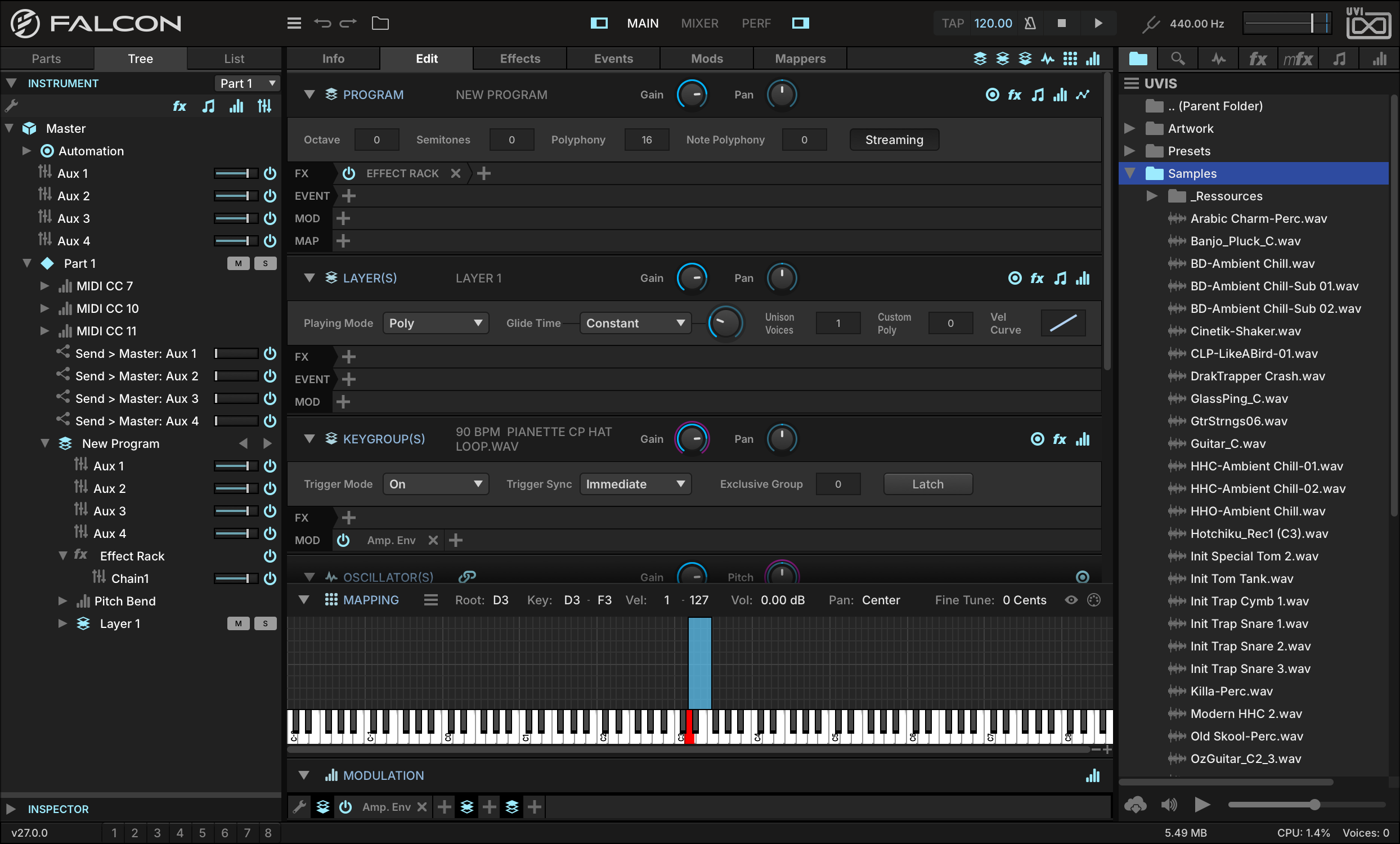
When the Effect Rack is added, it doesn’t add any audio processing on its own; instead, it creates a new FX chain. Navigate to the TREE tab and expand our new Effect Rack. Inside it is CHAIN 1. You can right-click this chain to add as many effects as you like.
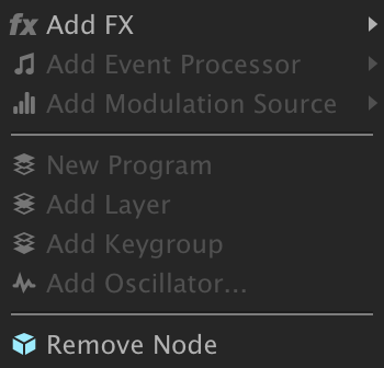
-
Let’s add a delay and a filter to chain 1, ANALOG TAPE DELAY and LOWPASS 24.
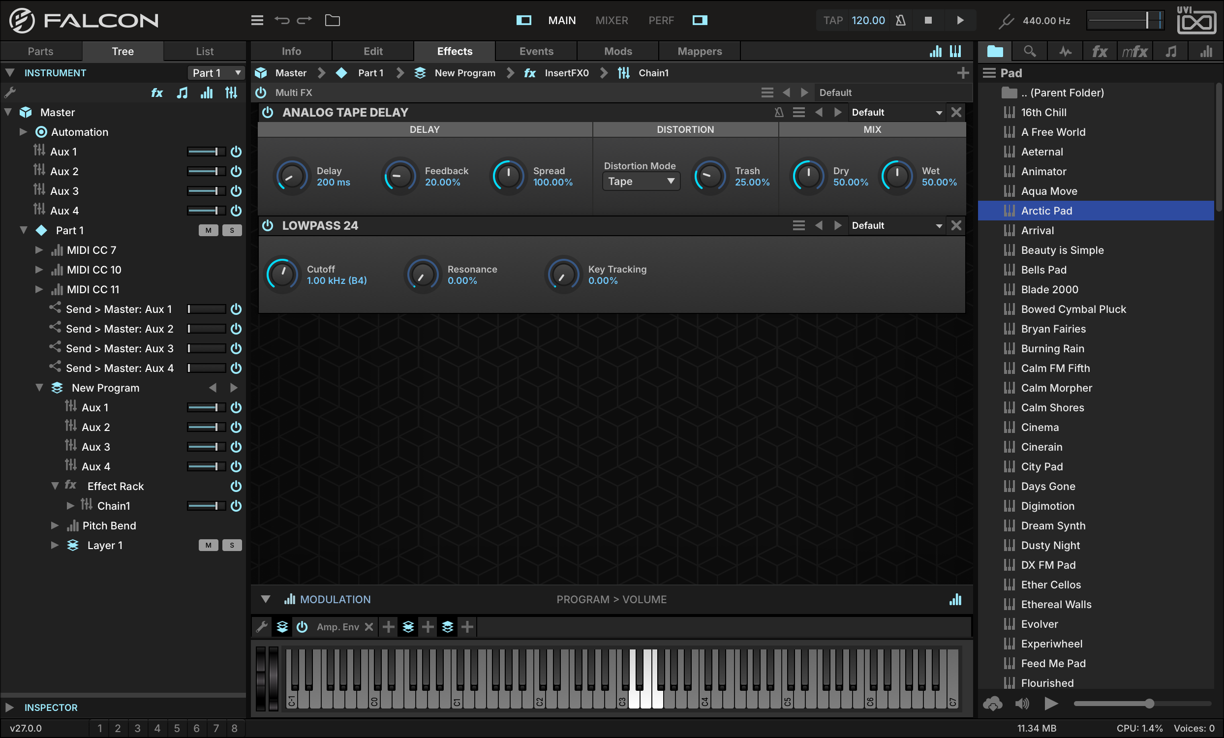
-
Switch to the EDIT tab, then show the Modulation Editor with its button in the upper-right toolbar of the Edit tab.
-
Now right-click the DELAY knob in the Analog Tape Delay effect and select ASSIGN TO EFFECT RACK MACROADD NEW MACRO. In the Editor below you will see the Macro modulator we just created along with all of its editable parameters. Locate the DISPLAYNAME field, double-click it and rename the macro DELAY. Do the same for the filter cutoff, renaming it CUTOFF.
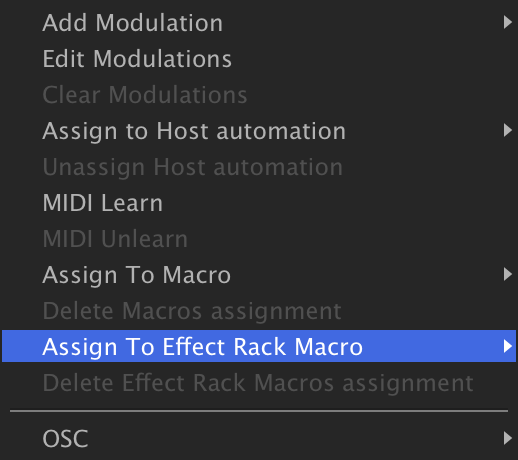

-
Now let’s head back to the Effect Rack “front panel” by selecting the Effect Rack in the Tree view. Now we see our two macros and the names we set for them.
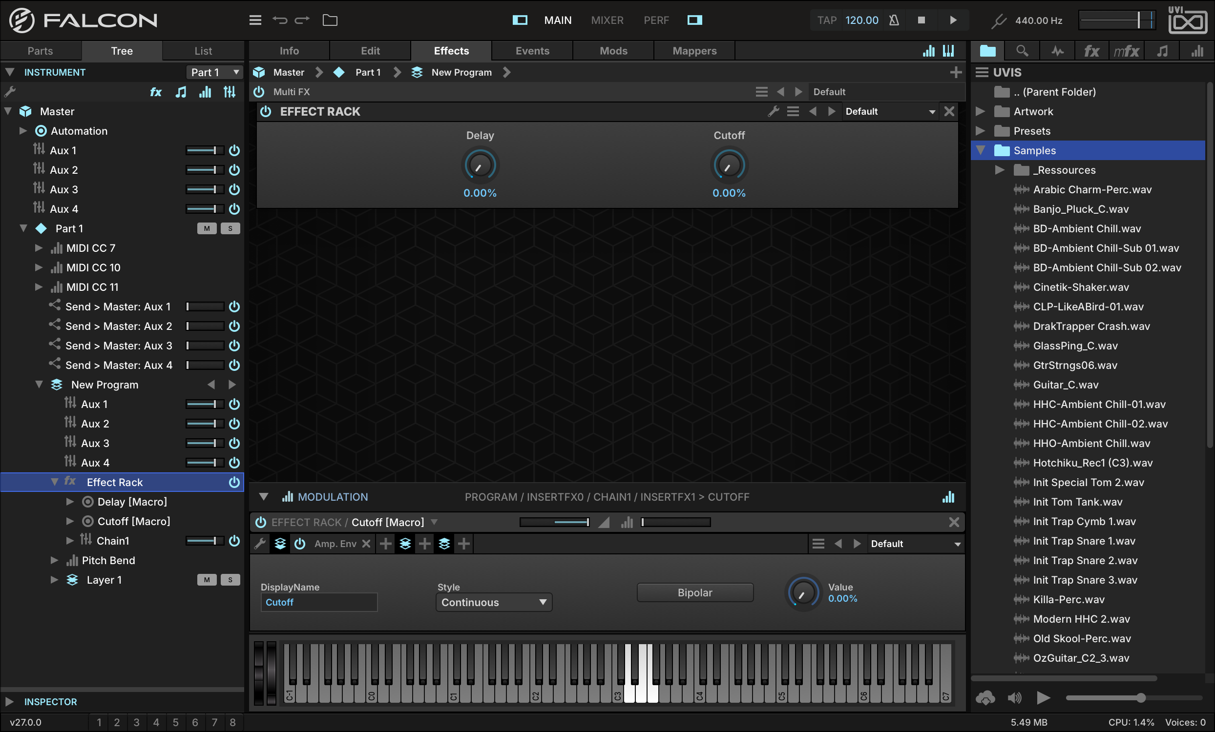
-
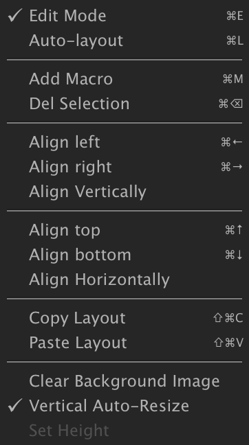
If you want to change the layout of the Macro panel, press Cmd/Ctrl+E to enter Edit mode, or click the wrench in the Effect Rack’s header. Select both macro knobs and right-click over the background for helpful layout options. You can also add a custom background by dragging an image onto the panel. Press Cmd/Ctrl+E again to exit Edit mode when your changes are complete.
-
To set the overall level of the FX chain, adjust the volume slider of the FX chain in the Tree view.
Using Macros
Macros are intermediary modulation sources which modulate other controls, useful for placing a small number of important controls on the “front panel” of a patch. Any parameter that can be modulated can be assigned to a macro, and a single macro can drive any number of parameters.
-
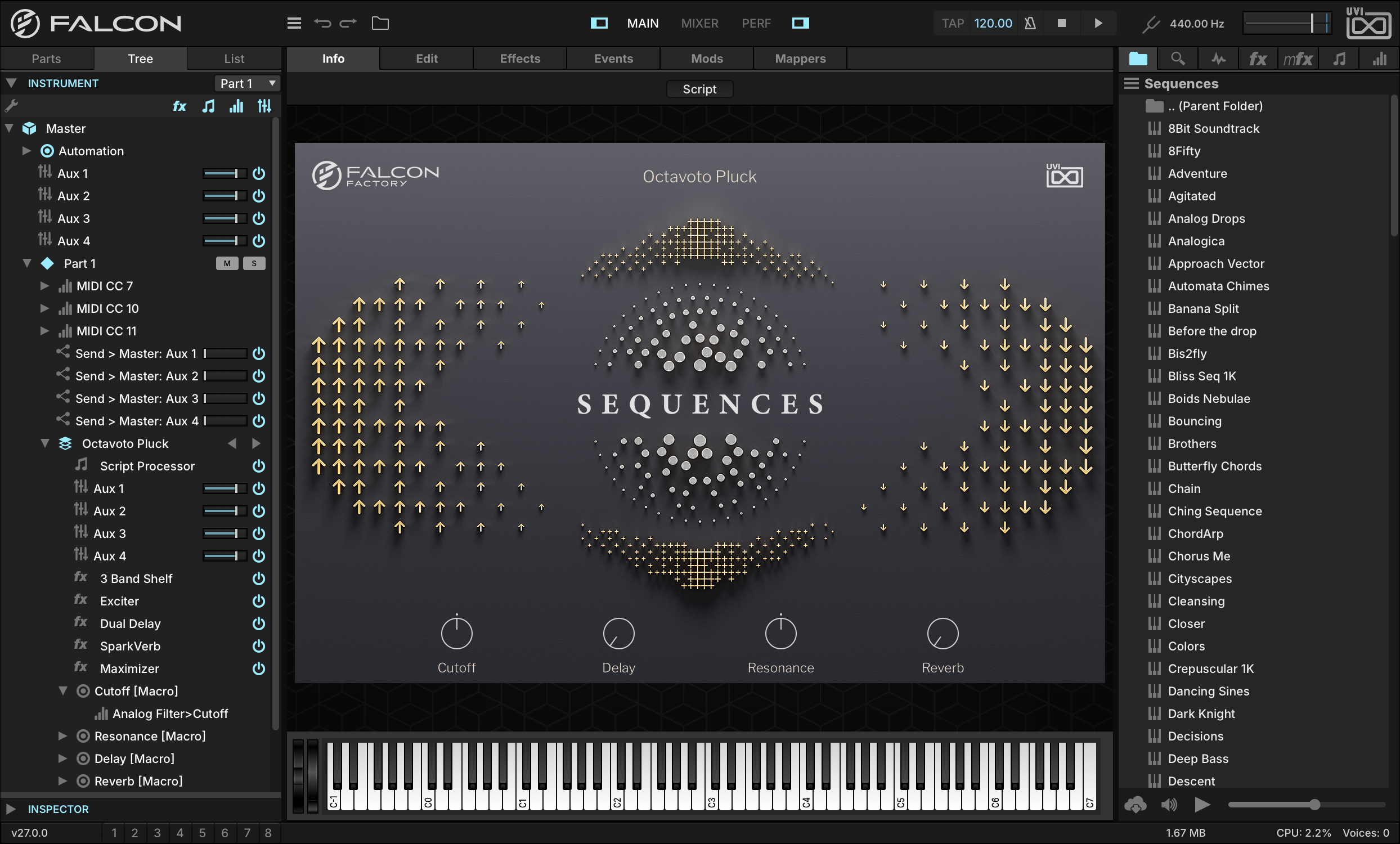
Let’s start with a program that already has some macros assigned, such as SEQUENCESOCTAVOTO PLUCK from the FALCON FACTORY REV2 Soundware. Load the program, then switch to the INFO tab in the Main view: its Cutoff, Delay, Resonance and Reverb knobs are macros.
-
To see which parameters the macros are assigned to, switch the left sidebar to the TREE tab. Press the arrow next to the macro name to expand it and display its assignments.
-
Let’s create a new macro. To create an adjustable vibrato, we can modulate keygroup pitch with an LFO and assign a macro to control the depth of the LFO.
-
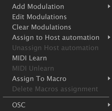
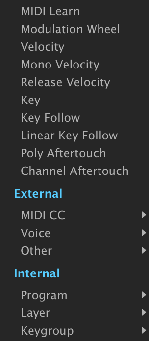
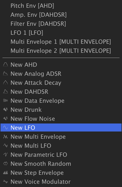
Switch to the EDIT tab, right-click the PITCH knob in the OSCILLATOR(S) header, and choose ADD MODULATIONKEYGROUPNEW LFO.
-
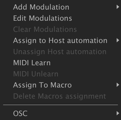
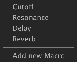
On the new LFO, set FREQ to 5.8 Hz and turn the DEPTH knob down to 0, then right-click it and choose ASSIGN TO MACROADD NEW MACRO.
-
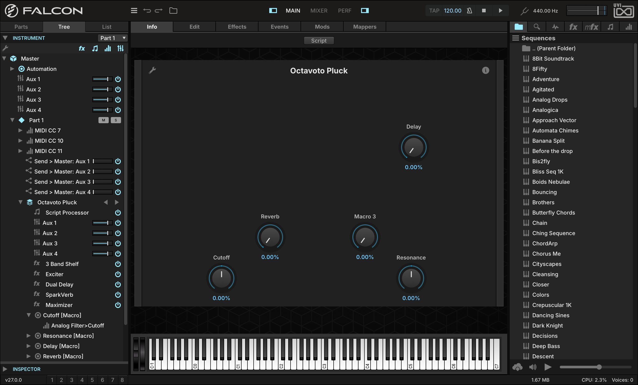
Switch back to the INFO tab. The program shows its own script front panel, where a macro added afterwards does not appear: press the SCRIPT button at the top of the Info tab to switch to the standard view, and you’ll see the new macro knob alongside the others. Turn the new knob, and you can hear the depth of the LFO modulation increasing.
-
To help remember what the macro is modulating, we can give the knob a more meaningful label and move it to a handy position as well. Press the EDIT button in the top left, then move the macro to line it up with the existing macros and double-click the label and enter a new name, such as VIBRATO. Press EDIT again to leave Edit mode.
Using Host Automation
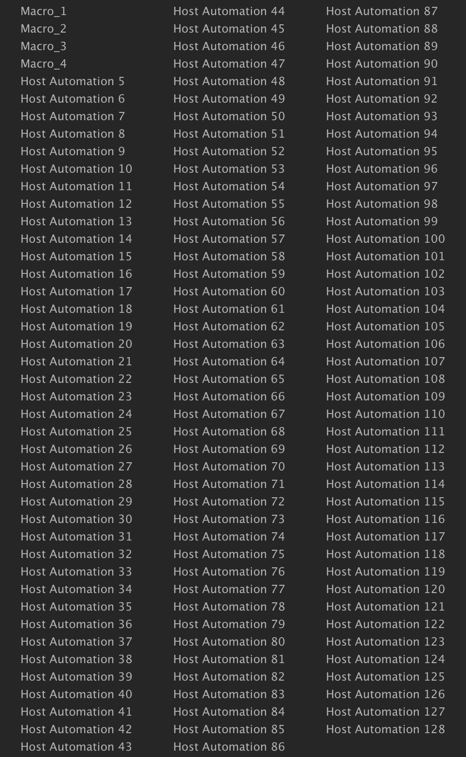
In addition to Falcon’s extensive internal modulation sources, when using Falcon as a plug-in you can take advantage of your host application’s automation capabilities. Each Falcon instance has 128 automation connections that can be assigned to individual controls.
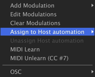
To make a host automation assignment, right-click a parameter, choose Assign to Host Automation, and choose one of the available items.
-
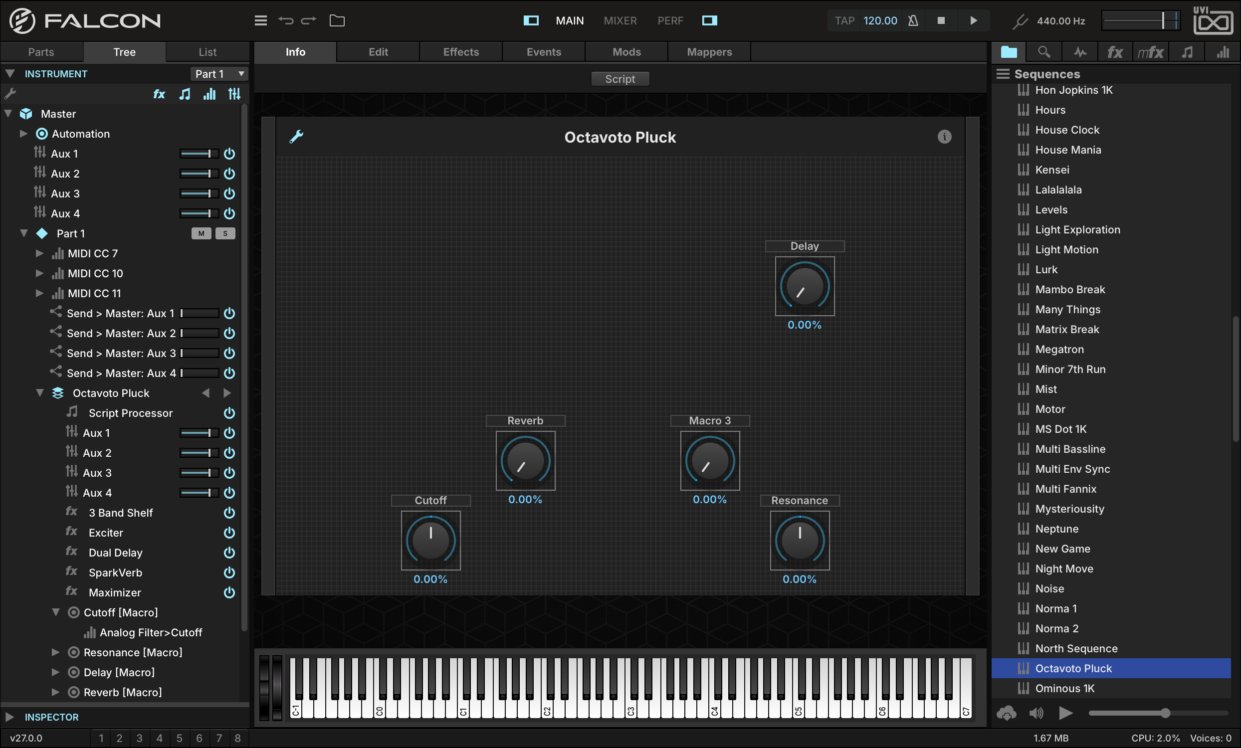
For example, load OCTAVOTO PLUCK (FALCON FACTORY REV2SEQUENCES), right-click Part 1’s VOLUME slider and choose ASSIGN TO HOST AUTOMATIONHOST AUTOMATION 5. The first four slots are already taken: the program publishes its four macros on them, and the menu names them after the macros.
-
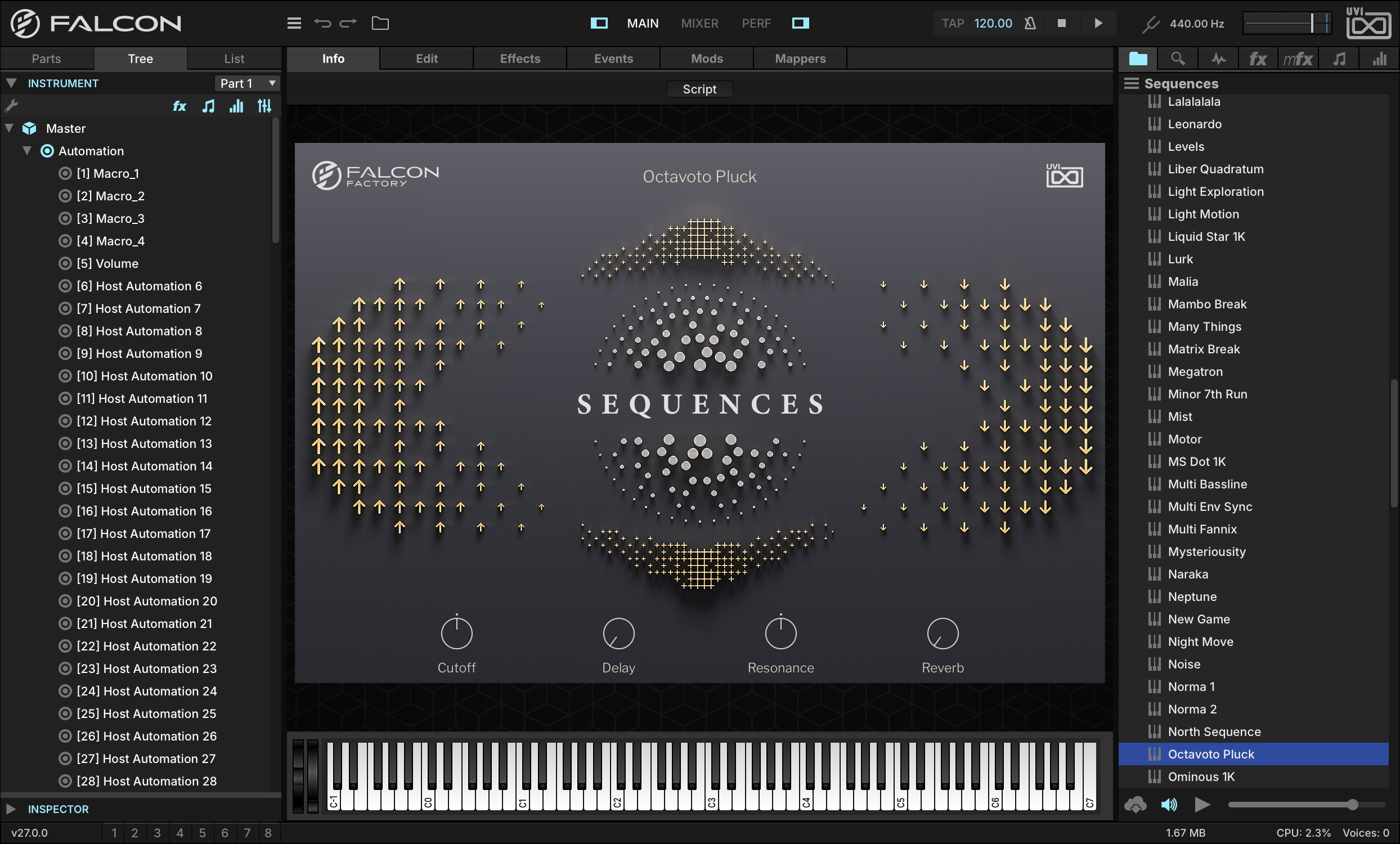
The name of the assigned parameter will be displayed in the TREE view.
-
If your host application supports it, the name of the assigned parameter may be displayed in the host application. Otherwise, the numbered parameter name (such as “Host Automation 1”) will be displayed.
Using Step Envelopes
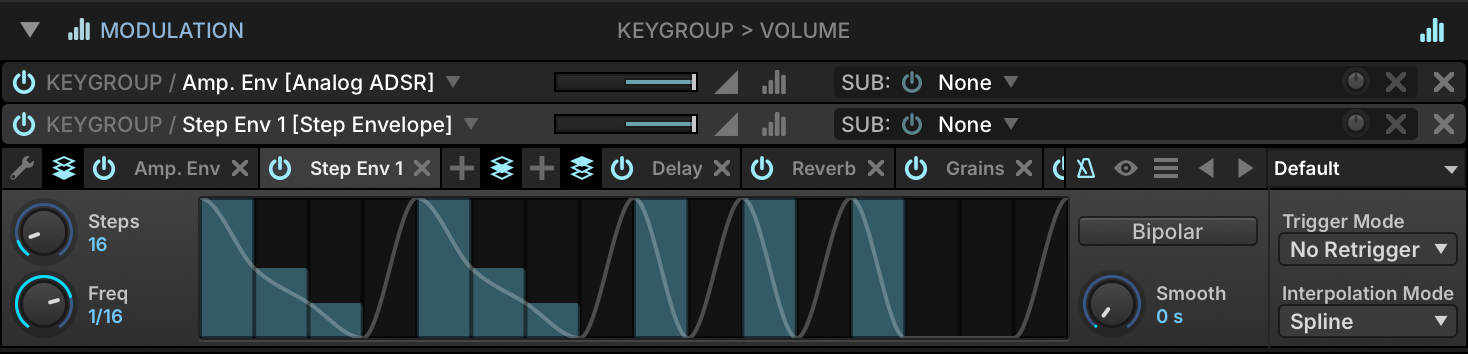
The Step Envelope is a programmable envelope for creating time-based effects, and makes a great programmable pattern sequencer.
-
A good way to understand the Step Envelope is to use it to modulate keygroup gain. Load PADSTRING ANALOG from the FALCON FACTORY REV2 Soundware.

-
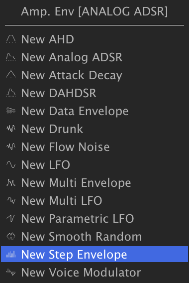
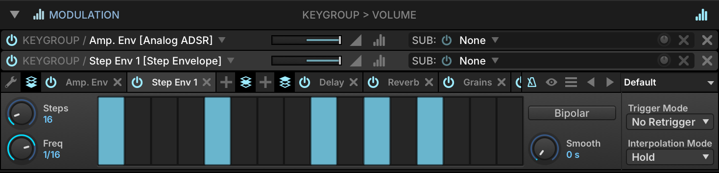
Right-click the keygroup GAIN knob and choose ADD MODULATIONKEYGROUPSTEP ENVELOPE. Play a few notes, and you’ll hear the signal gated on the empty steps, and full volume on the steps with full bars.
-
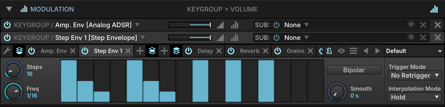
Each step doesn’t have to be fully on or fully off, however — you can continuously adjust the value of each step between the two.
-
Adjust the value of a few steps to half or a quarter, and you’ll hear an effect similar to delay feedback taps. You can also apply smoothing between steps to avoid abrupt transitions, pops and clicks.
-
To enable TEMPO SYNC for the Step Envelope, click the metronome icon in the toolbar of the Modulation Source Editor.
-
You can also create LFO-like patterns that glide smoothly from step to step. With Interpolation Mode set to SPLINE, a continuous line is interpolated from the individual bars, creating a continuously variable modulation source that’s suited for pitch sweeps, wobbles, and so on.
Using Multi Envelopes
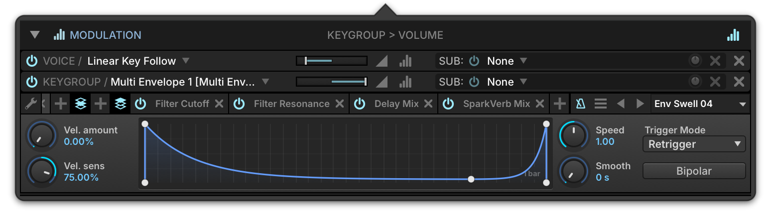
The Multi Envelope is an envelope with a user-defined shape, consisting of any number of points. This allows for truly customized envelopes beyond classic DAHDSR envelopes, such as sweeps that evolve over a long period of time or looped LFO-like shapes.
-
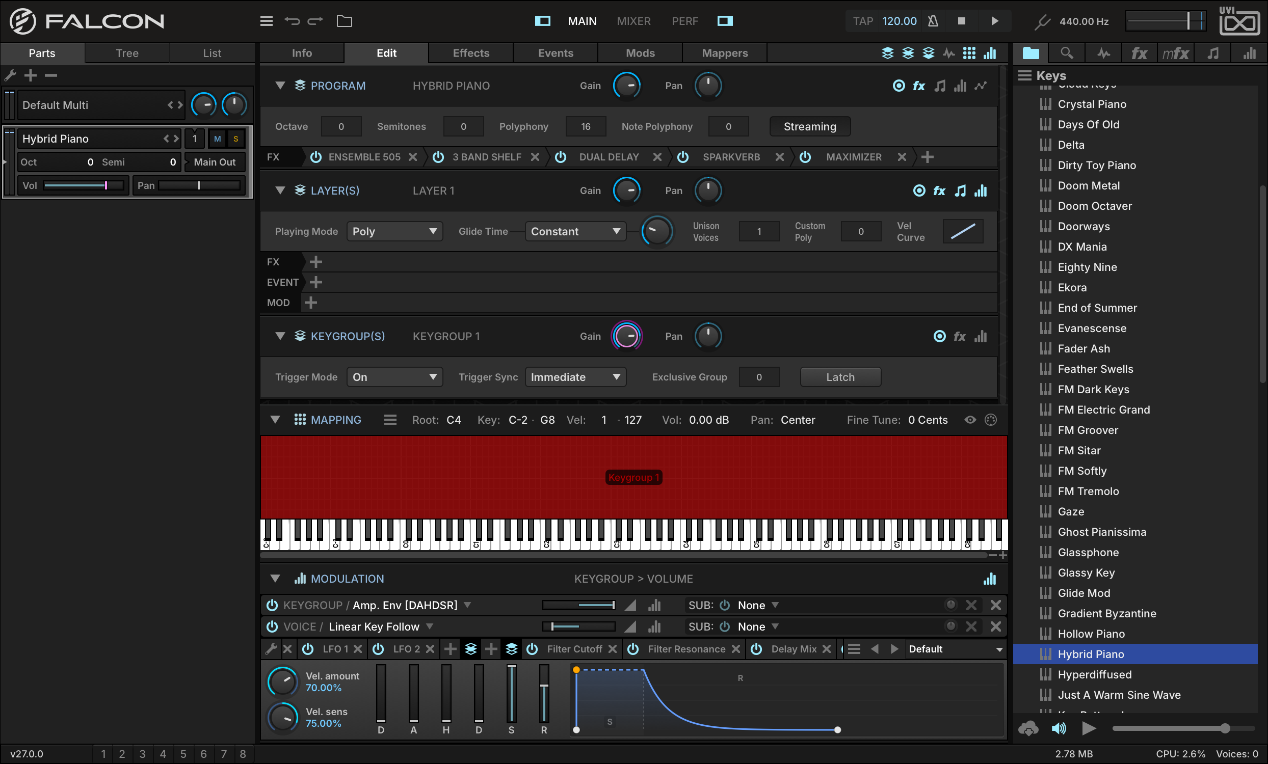
A good way to understand the Multi Envelope is to use it to modulate keygroup gain. Load KEYSHYBRID PIANO from the FALCON FACTORY REV2 Soundware.
-
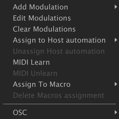
Go to the EDIT tab, right-click the keygroup GAIN knob and select EDIT MODULATIONS.
-
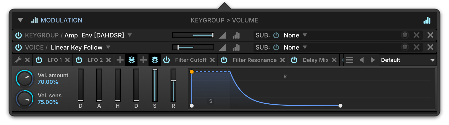
A pop-up editor will appear showing all of the modulation sources linked to the control. Right-click the AMP. ENV. name and replace it with a MULTI ENVELOPE.
-
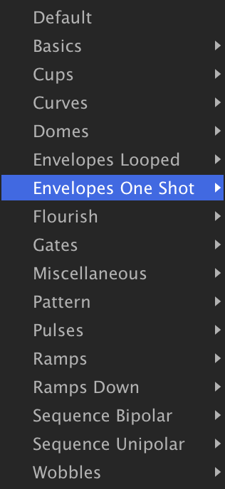
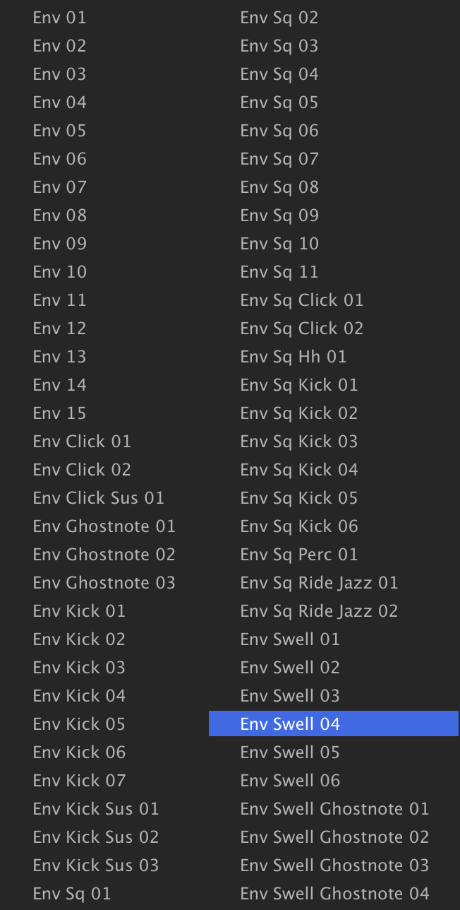
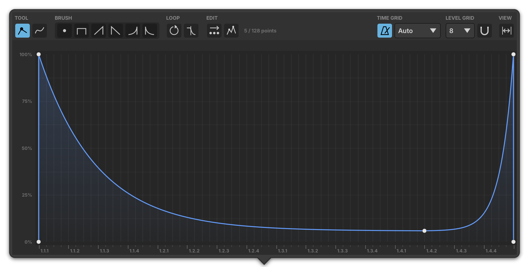
Now let’s load a Multi Envelope preset: use the PRESET MENU to select ENVELOPES ONE SHOTENV SWELL 04, and play a few notes.
-
If you’d like a bigger canvas to work on, press the eye button next to the Preset File menu.
-
To loop part of the envelope, drag the L and R flags in the ruler above the curve onto two points: while the note is held, the envelope repeats between them, like an LFO. If the preset has no loop, right-click the curve and choose ADD LOOP first.
You have replaced a keygroup’s amplitude envelope with a drawn, loopable Multi Envelope; for all of its controls and loop options, see Modulators › Multi Envelope.
Using OSC
Using OSC (Open Sound Control)
Open Sound Control is a protocol used to communicate between different computers and other audio devices. OSC is commonly used for remote control of software, such as from a central sequencer that’s driving Falcon installations on multiple networked computers, or for touchscreen control from a wireless mobile device.
-
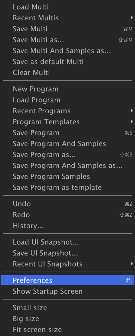
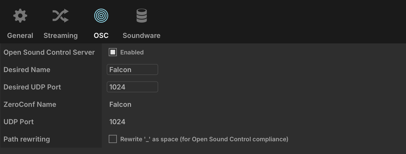
To start using OSC in Falcon the OSC server needs to be enabled. Open the Preferences window from the Main Menu, select the OSC page, and enable OPEN SOUND CONTROL SERVER. This will make Falcon discoverable on the network by other OSC-enabled applications. Falcon will automatically negotiate a unique name and port number.
-
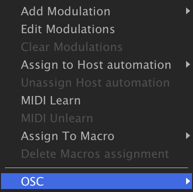
Each one of Falcon’s parameters that can be controlled externally has an OSC Path that uniquely identifies it, such as “/uvi/Part 3/Program/Layer 1/Gain”. When a parameter is right-clicked, the contextual menu displays the parameter’s OSC path.
-
There is also a convenient shortcut provided for copying the parameter’s OSC path to the clipboard. You can then use that OSC path in any OSC-equipped application to control that parameter.

Learning: Events
Events
We’ve looked at ways to create and apply effects to sounds, and we’ve looked at ways to modulate them; now let’s take a look at Event processors.
Event modules can generally be thought of as MIDI effects, processing incoming MIDI signals or generating them, though with the Script Processor it’s possible to extend that paradigm to include extremely sophisticated creative devices and interface customization.
The most commonly used Event processors are the Arpeggiator, Micro Tuner and MIDI filters like the Chorder, Tonal Harmonizer and Strum. These are easily mastered devices providing great performance utility.
In the following lessons we’ll take a look at a few of these devices and some of the ways that we can effectively implement them in our own projects.
Using the Arpeggiator
The Arpeggiator is a classic synthesizer effect which modifies the incoming notes and plays them in a programmable pattern to create a dynamic sequence.
-
Let’s start by loading the KEYSHYBRID PIANO program from the FALCON FACTORY REV2 Soundware.
-
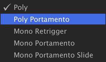
In the EDIT tab, change the play mode to POLY PORTAMENTO.
-
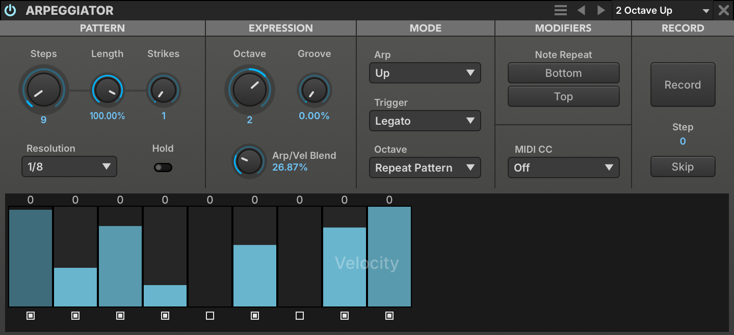
Switch over to the EVENTS tab, hit the + button and select the ARPEGGIATORARP BASIC2 OCTAVE UP preset.

-
Let’s slow the RESOLUTION down to 1/8 and add a few more steps to this pattern. Change STEPS to 9 and enable step 9 by clicking the step state box underneath it, so that steps 1, 2, 3, 4, 6, 8, and 9 are On and steps 5 and 7 are Off.
-
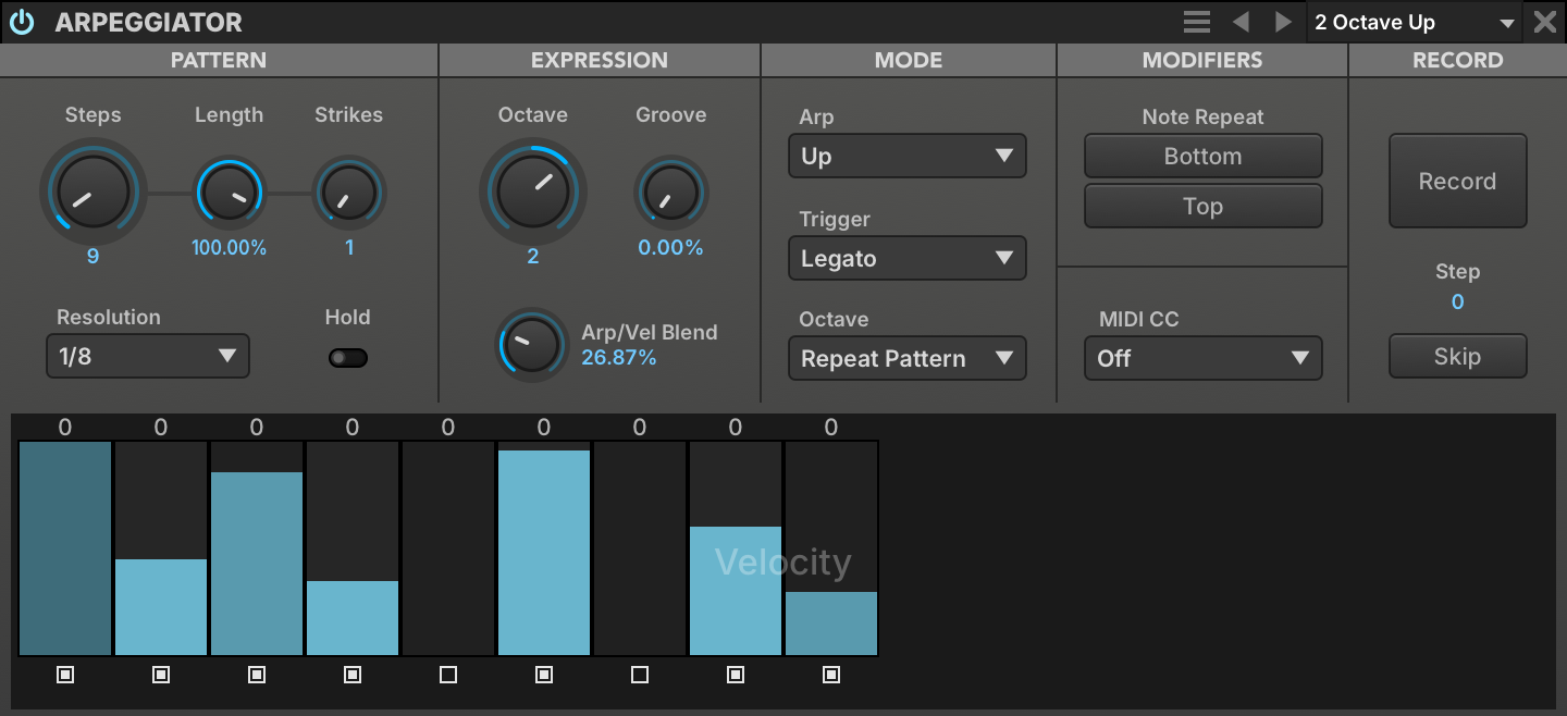
Now let’s customize the value of these steps: adjust the velocity by click-dragging in the graph, and modify the step length by Shift-click-dragging.
-
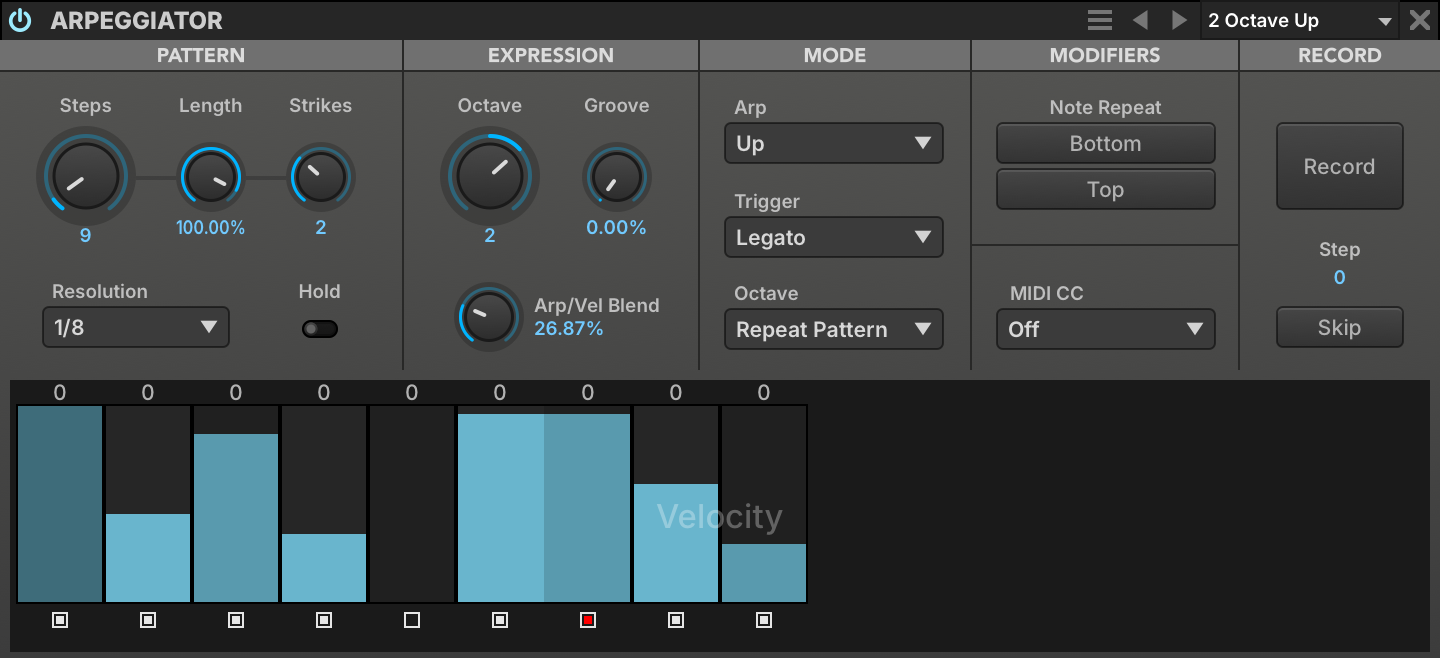
To give the pattern a more defined groove let’s change STRIKES to 2 and Shift-click the step state button of step 7 to merge it with the step before it.
-
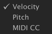
The Arpeggiator has three layers: Velocity and Pitch for notes, and MIDI CC for generating a MIDI CC as an additional control signal. Right-click the step grid to change which layer is displayed. The step state (on, off, or merged) is shared between the three layers, but the velocity, pitch, and MIDI CC values of each step are independent.
Using the Micro Tuner
The Micro Tuner allows the exploration of many unique and interesting temperaments, both modern and classical. It also allows instruments from other musical traditions to be played in their own tuning.
For this example we’re going to create an instance of Falcon in 12-tone Pythagorean temperament with C4 at 256 Hz. Pythagorean tuning is based on a stack of intervals called perfect fifths, each tuned in the ratio 3:2, which gives pure fifths.
-
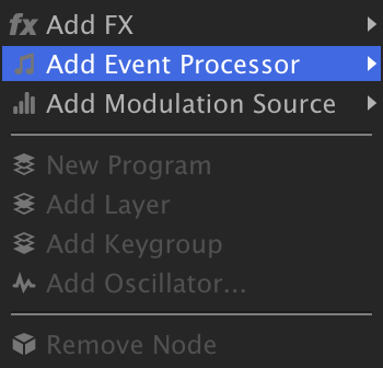
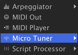
Navigate to the TREE tab, right-click the MASTER node and select ADD EVENT PROCESSORMICRO TUNER. Placing the Micro Tuner at the Master level means that all parts in Falcon will be affected; this is a great way to ensure that any and all instruments loaded or created from here on out will be in tune.
-
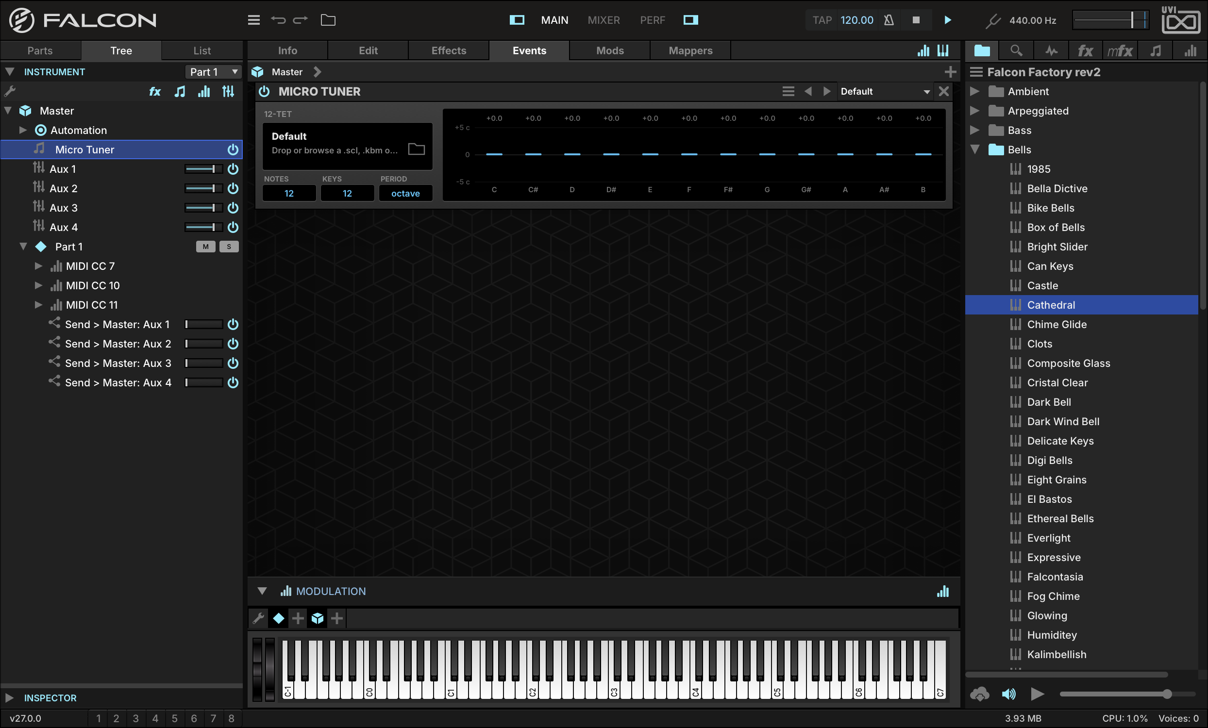
Double-click the new Micro Tuner to reveal it in the EVENTS editor to the right. In its default state the Micro Tuner doesn’t do anything. From here we could load an existing preset, but for this example we’re going to use a custom Scala file.
-
Let’s create a new Scala file to describe 12-tone Pythagorean temperament. Create a new text document and paste in the following:
-
! pyth_12.scl ! 12-tone Pythagorean scale 12 ! 2187/2048 9/8 32/27 81/64 4/3 729/512 3/2 6561/4096 27/16 16/9 243/128 2/1 -
Save this document as
pyth_12.scl(UTF-8 encoding) and drag the resulting file onto your Micro Tuner. You can save this as a Micro Tuner preset and it will be available for future projects.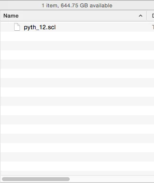
-
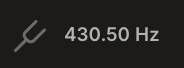
Now change the GLOBAL TUNE in Falcon’s toolbar to 430.5 Hz. With A4 tuned to 430.5 Hz, C4 will be at 256 Hz. This would be a good time to save out the Multi if you wanted to create a template or even SAVE AS DEFAULT MULTI if you consistently use a particular tuning.
-
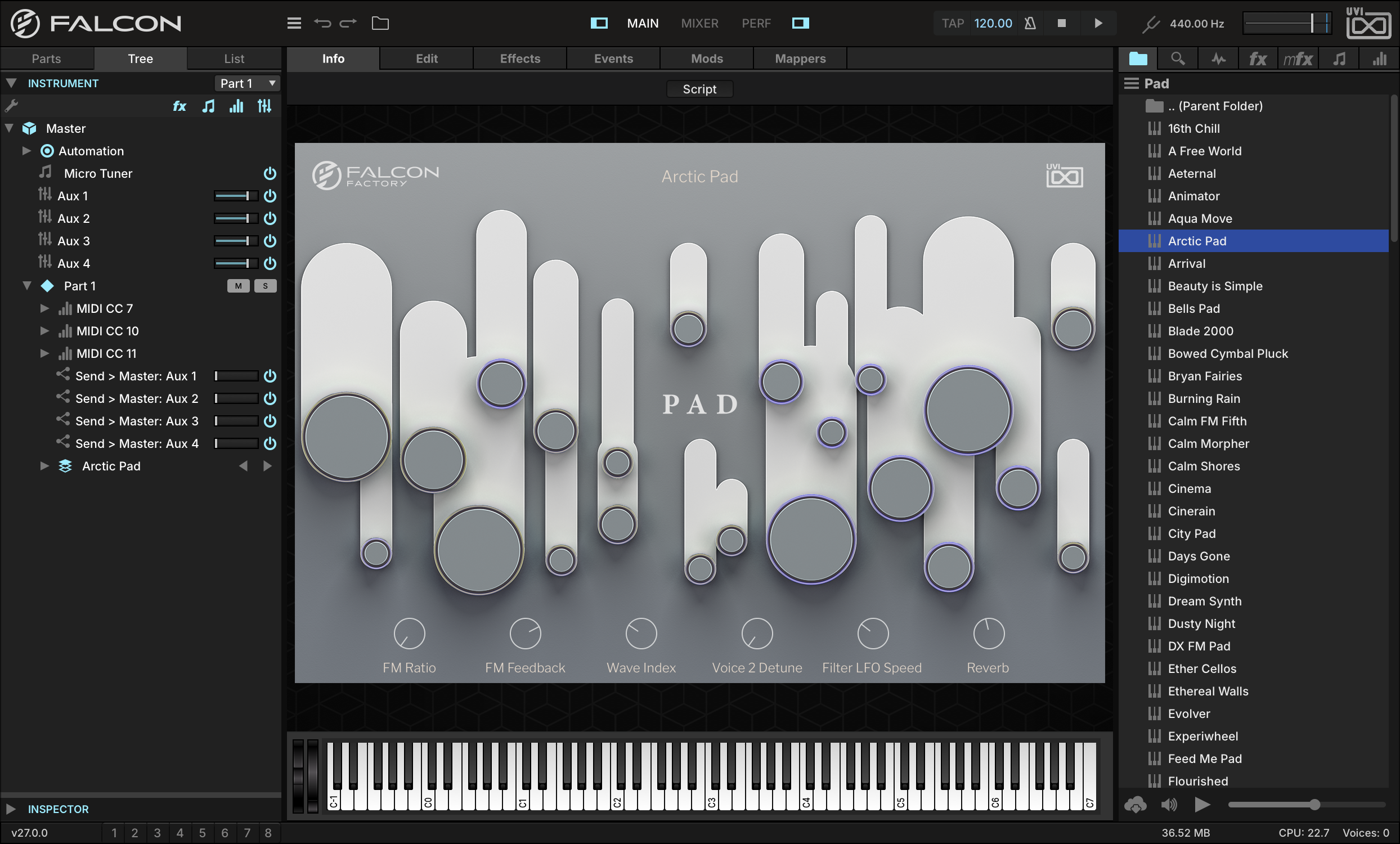
Now let’s load a patch to hear the results. For something with a long release, try PADARCTIC PAD from the FALCON FACTORY REV2 Soundware.
Falcon comes with many Micro Tuner presets, and you can easily add more with custom Scala files.
Using the Script Processor
The Script Processor module provides custom event processing capabilities, using the Lua-based scripting language UVIScript.
The Script Processor module has two primary sets of controls: the standard controls for interacting with the script itself, and the controls defined by the loaded script (knobs, buttons, menus, and so on).
-
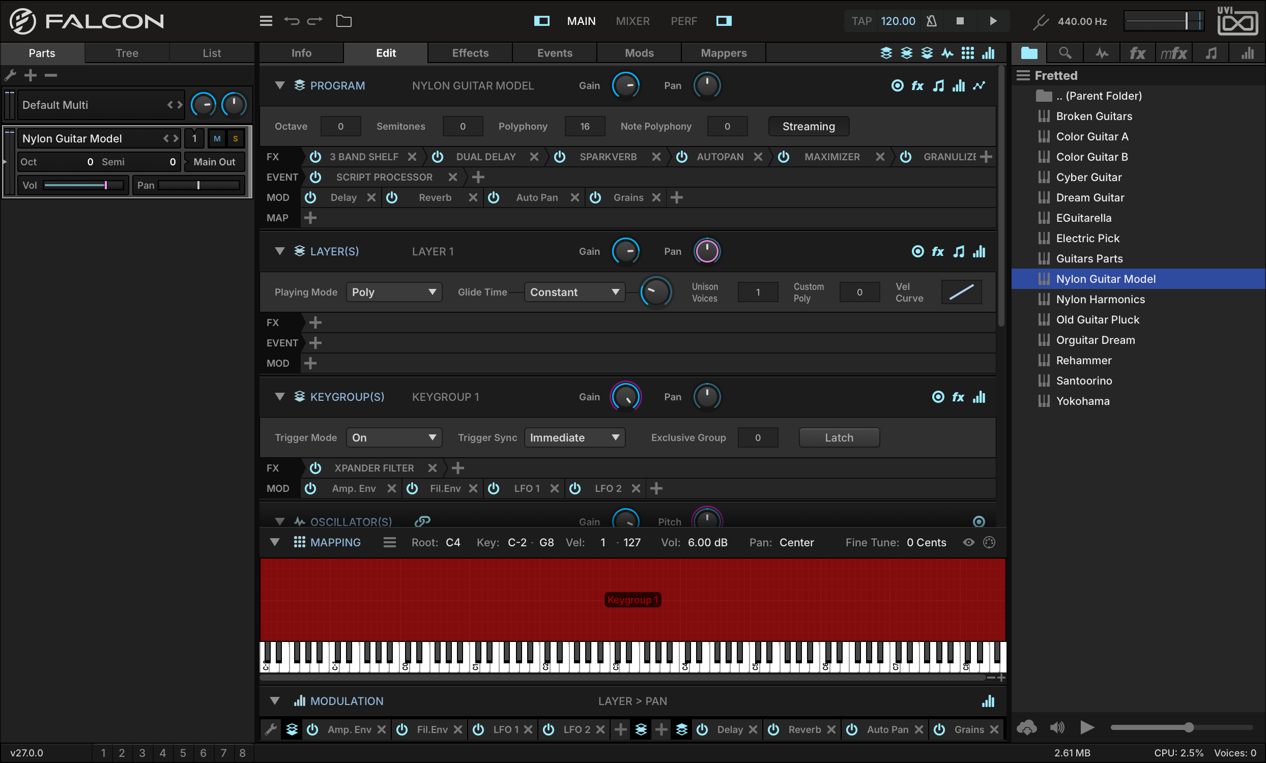
Let’s load the FRETTEDNYLON GUITAR MODEL program from the FALCON FACTORY REV2 Soundware. Then go to the EVENTS tab, add the Script Processor module, then load the PERFORMANCESTRUM preset.
-
The script adds four parameters: DIRECTION, which orders the notes (up, down, alternating or random), LAG (0–200 ms), the gap between them, HUMANIZE, which randomizes that gap, and VEL. SENS., which shortens it as you play harder. Adjust LAG and play a chord, and you’ll hear the notes played in succession as if strummed rather than triggered all at once.

-
Let’s start with a simple script that prints some information about each note to the Script Processor console. Enter the following code into a text editor and save the file as
printer.lua:printer = OnOffButton("Print", true) function onNote(e) if printer.value == true then print("On : ", e) end postEvent(e) end function onRelease(e) if printer.value == true then print("Off : ", e) end postEvent(e) end -
In the Script Processor module, press the LOAD SCRIPT button on the left and choose the
printer.luafile.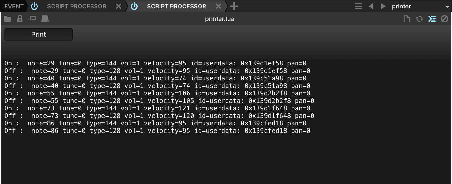
-
Then enable SHOW SCRIPT CONSOLE OUTPUT at the right of the module’s toolbar, which is generally used for displaying debug messages, and play a few notes—you will see that as each note is triggered and released, a line of information about the note is printed to the console so long as the script’s PRINT button is enabled. If you disable the Print button, the messages no longer print to the console.
You have loaded a factory script and written one of your own that logs every note it receives. To go further, see Scripting in Lua, and for the module’s own controls, Event Processors › Script Processor.
Structure
Hierarchy
Falcon is a hierarchy of components, structured so that you can focus on the high-level arrangement or drill down to deeper levels as you prefer.
Multi 1 per instance
The whole Falcon instance: every part, plus the master level — master effects, the master aux buses fed by each part’s sends, and master modulators and event processors. In the Tree and in menus, this level appears as the Master node. Saving the multi saves all of it, including each part’s program.
Part 1 or more
A slot in the multi that plays one program. The part has its own MIDI input, audio output, volume, pan and transposition, and its own effects, modulators and event processors, separate from the program’s. Part settings are saved in the multi, not in the program.
Program 1 per part
The instrument you load and save as a preset. It holds program-wide settings (octave, polyphony, streaming), effects that every layer passes through, program modulators and event processors, and the mappers, which exist only at this level. Its own aux buses, the program aux FX, are fed by the sends of its layers and keygroups.
Layer 1 or more
Groups keygroups and decides how they play: play mode (poly or mono), portamento, unison voices and velocity curve. Its effects, modulators and event processors only affect its own keygroups. It is the lowest level that takes event processors.
Keygroup 1 or more
The ground level: a key and velocity range (edited in the Mapping Editor), the oscillators it triggers, and their trigger settings. Effects here run per voice, with the extra CPU cost that implies. Keygroups do not take event processors.
Effects Multi
Audio effects processing the signal of this level and everything below it, in the order they are listed (left to right).
At this level: Master insert effects, and the master aux effects fed by each part’s sends.
Modulators Multi
Modulation sources — envelopes, LFOs, macros… They change parameter values on this level and below, but never carry audio or MIDI themselves.
Events Multi
MIDI event processors — arpeggiators, micro tuners, script processors… They transform MIDI before it reaches the levels below.
At this level: Master event processors are the first to see an incoming note.
Effects Part
Audio effects processing the signal of this level and everything below it, in the order they are listed (left to right).
Modulators Part
Modulation sources — envelopes, LFOs, macros… They change parameter values on this level and below, but never carry audio or MIDI themselves.
Events Part
MIDI event processors — arpeggiators, micro tuners, script processors… They transform MIDI before it reaches the levels below.
Effects Program
Audio effects processing the signal of this level and everything below it, in the order they are listed (left to right).
Modulators Program
Modulation sources — envelopes, LFOs, macros… They change parameter values on this level and below, but never carry audio or MIDI themselves.
At this level: Envelopes placed here still retrigger with each note when they modulate a keygroup parameter; on a layer or program parameter they do not.
Events Program
MIDI event processors — arpeggiators, micro tuners, script processors… They transform MIDI before it reaches the levels below.
Mappers Program
Modulation mappers sit between a modulation source and a parameter and reshape the source’s values along the mapper curve. They exist on the program only.
Effects Layer
Audio effects processing the signal of this level and everything below it, in the order they are listed (left to right).
Modulators Layer
Modulation sources — envelopes, LFOs, macros… They change parameter values on this level and below, but never carry audio or MIDI themselves.
At this level: Envelopes placed here still retrigger with each note when they modulate a keygroup parameter; on a layer or program parameter they do not.
Events Layer
MIDI event processors — arpeggiators, micro tuners, script processors… They transform MIDI before it reaches the levels below.
At this level: An arpeggiator added here only plays this layer’s keygroups.
Effects Keygroup
Audio effects processing the signal of this level and everything below it, in the order they are listed (left to right).
At this level: Effects run once per voice: better separation, more CPU than on the levels above.
Modulators Keygroup
Modulation sources — envelopes, LFOs, macros… They change parameter values on this level and below, but never carry audio or MIDI themselves.
At this level: Parameters at this level are modulated per voice, so the envelopes assigned to them retrigger with each note.
Oscillators Keygroup
Oscillators generate the initial sound, by sampling or by synthesis. A keygroup can hold several, layered freely.
Step 1 / 10 Multi · MIDI
A MIDI note enters the multi. Master event processors see it first.
Step 2 / 10 Part · MIDI
Every part whose MIDI input matches the note’s port and channel receives it and runs it through its own event processors.
Step 3 / 10 Program · MIDI
The note passes through the program’s event processors.
Step 4 / 10 Layer · MIDI
Each layer runs the note through its own event processors. This is the last level where MIDI can be changed.
Step 5 / 10 Keygroup · MIDI
Every keygroup whose key and velocity range contains the note starts a voice, which retriggers the envelopes modulating its parameters.
Step 6 / 10 Keygroup · Audio
The keygroup’s oscillators generate the audio, and its effects process it, voice by voice.
Step 7 / 10 Layer · Audio
The audio climbs back up: the layer’s effects…
Step 8 / 10 Program · Audio
…the program’s effects…
Step 9 / 10 Part · Audio
…the part’s effects, on the way to the part’s audio output…
Step 10 / 10 Multi · Audio
…and the master effects, before Falcon’s outputs. Modulators act on parameters at every step without ever being on the audio or MIDI path.
For example, a multi might contain two parts, shown below. The first plays a simple program: a single layer holding a single keygroup, whose only oscillator is a Pluck, routed into a spectrum analyzer on the program. The second plays Brush Stack Dark, from UVI Augmented Piano: several sustain, release and pedal-release layers, each holding dozens of keygroups with one sample per note, a script processor, envelopes and LFOs on the program, and a program effect chain from convolver and EQ to delay and reverb.
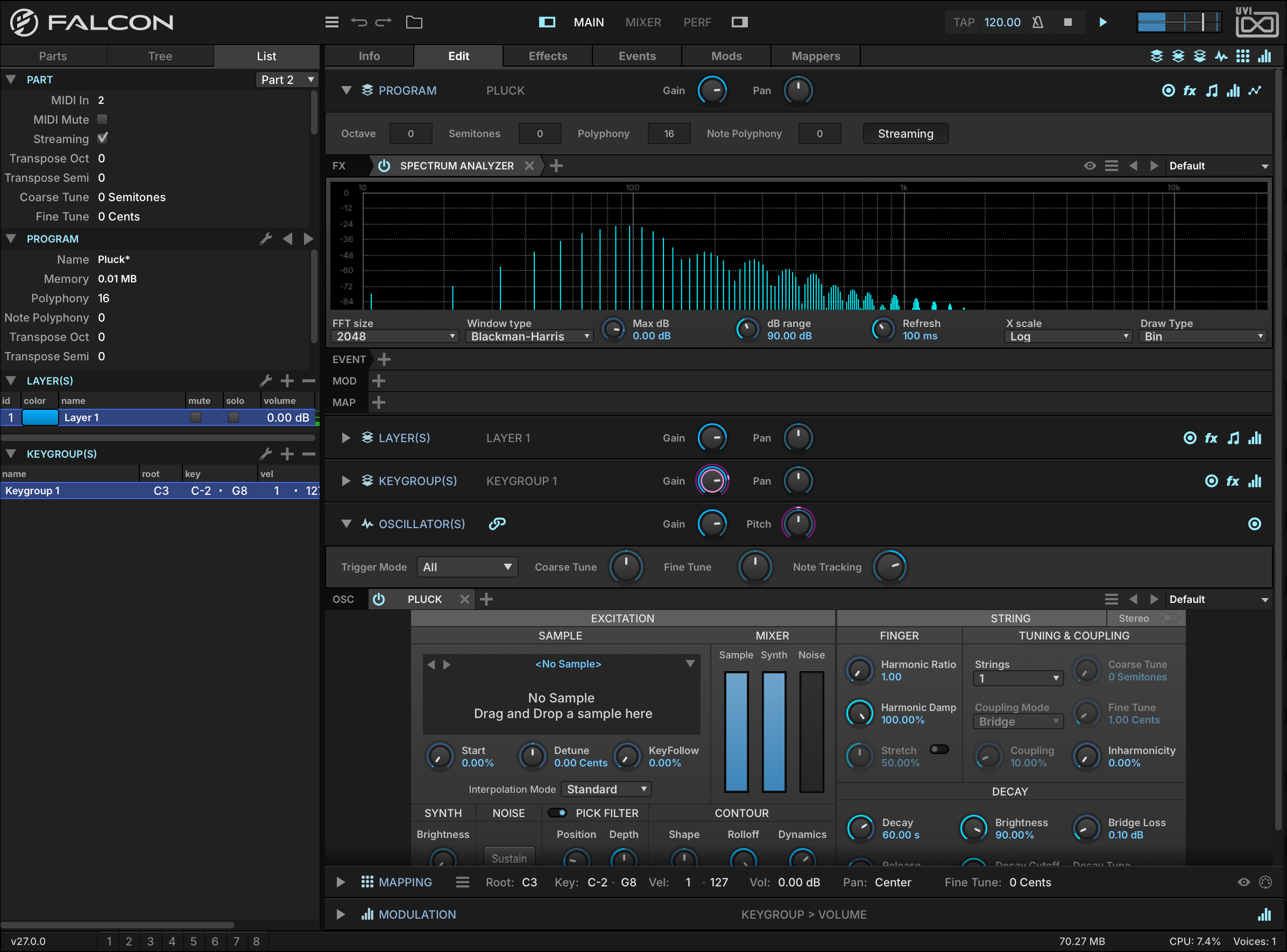
A single Pluck oscillator routed into a spectrum analyzer
- 1 One layer, one keygroup
The List view spells the program out: a single layer holding a single keygroup that spans the whole keyboard — the smallest program there is.
- 2 Program effects
A Spectrum Analyzer inserted on the program. Everything the program plays passes through it, so it shows the harmonics of the note being held.
- 3 Layer and keygroup
The LAYER(S) and KEYGROUP(S) sections are collapsed here; with a single one of each there is nothing else to select.
- 4 Pluck oscillator
The keygroup’s only oscillator. Pluck is a string-synthesis oscillator: a short excitation — pitched oscillator, noise or sample — is fed through a filtered delay line. See Oscillators › Pluck.
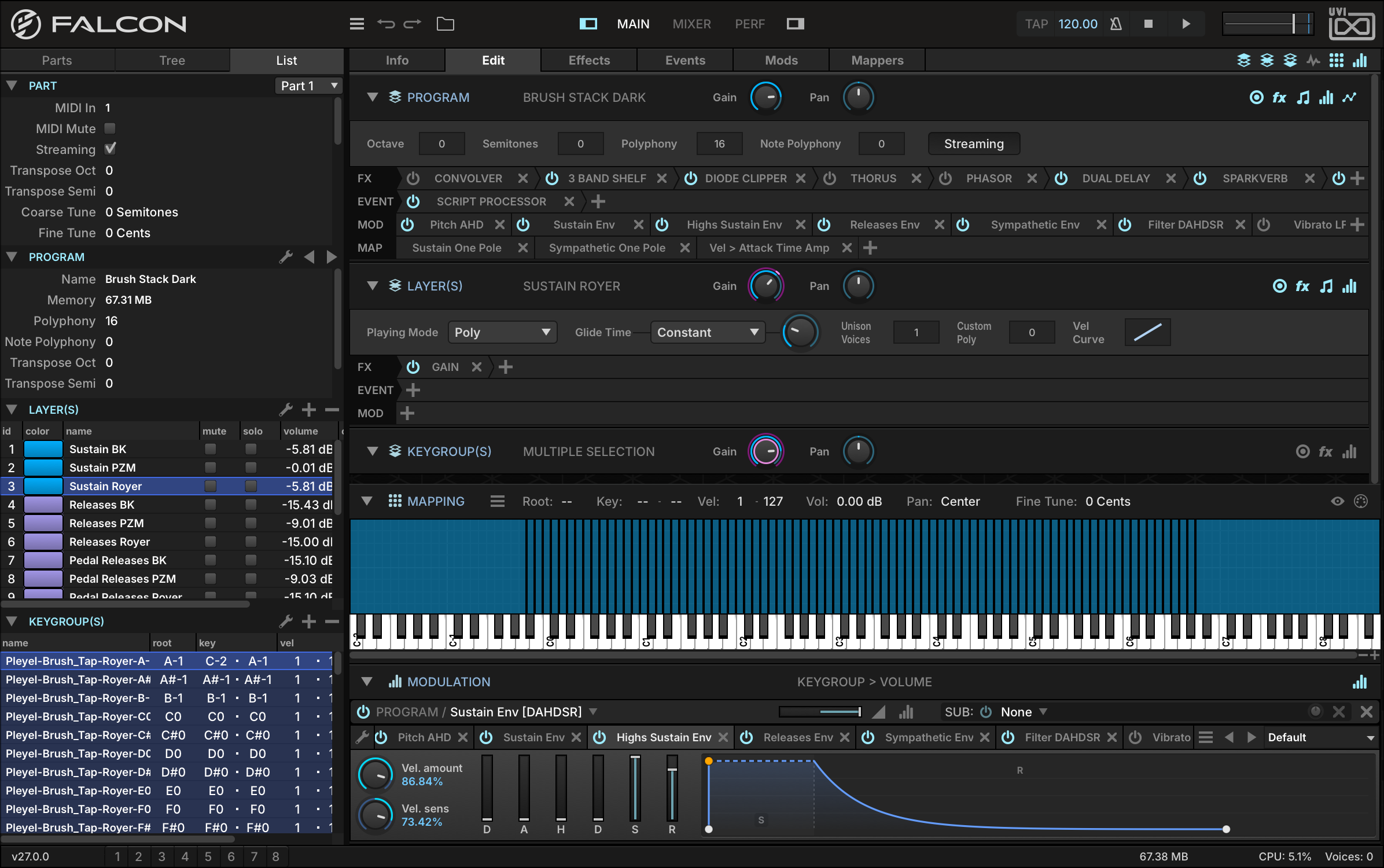
Dozens of keygroups make up just one of the many layers of Brush Stack Dark, from UVI Augmented Piano
- 1 Layers
Each row is a layer, with its own mute, solo and volume: sustain, release and pedal-release layers, several of each.
- 2 Keygroups
The keygroups of the selected layer — one per sampled note, each with its root key and its key and velocity range.
- 3 Program effects
Every layer passes through this chain: convolver, EQ, clipper, chorus, phaser, delay and reverb, processed left to right.
- 4 Program event processors
A Script Processor handles incoming notes before they reach the layers.
- 5 Program modulators
Envelopes for the sustain, the highs, the releases and the sympathetic resonance, a filter envelope, and vibrato and tremolo LFOs.
- 6 Mappers
Modulation mappers, which only exist at program level.
- 7 Layer
The selected layer, Sustain Royer: play mode, glide, unison and velocity curve, and its own effects, events and modulators — a single Gain effect here.
- 8 Keygroups
MULTIPLE SELECTION: every keygroup of the layer is selected, so an edit applies to all of them at once.
- 9 Mapping
The selected keygroups laid out across the keyboard, one column per note.
At its simplest, you can launch Falcon, load some instruments or loops, and just begin playing without worrying about how it’s all put together. At the other end, you can craft your own advanced, multi-layered programs from scratch containing dozens or hundreds of oscillators with numerous modulation sources, and then mix many instruments and loops together using multiple parts and effects chains.
The sounds included with Falcon or with partner Soundware contain highly detailed and richly varied programs that don’t require any editing at all. However, Falcon also provides the means to modify and extend sounds, which can be peeled back one layer at a time for increasingly detailed adjustments.
Components
The basic components of Falcon are oscillators, effects, event processors and modulators. These components, described in the following sections, can be combined in near-infinite variations to produce compelling sounds and instruments.
Oscillators
Oscillators generate the sound. Each keygroup holds one or more of them, of two types: sampling oscillators, which play back audio samples, and synthesis oscillators, which generate the sound without samples. For each oscillator type, see Oscillators.
Effects
Effects process the audio signal, from filters, delays and reverbs to analysis tools such as spectrum analyzers. They can be inserted at every level, from a single keygroup up to the master output, and a whole chain can be saved and recalled as a Multi FX preset. For using effects, see Interface › Effects; for each effect type, Effects.
Modulators
Modulators move the values of controls; they never carry audio or MIDI themselves. Internal sources (envelopes, LFOs, macros) come from Falcon itself, and envelopes and LFOs can be created at every level from the master down to the keygroup; external sources include MIDI messages and host automation. For using modulation, see Interface › Modulation; for each modulator type, Modulators.
Event Processors
Event processors transform or generate MIDI before it reaches the oscillators, from arpeggiators and micro-tuners to script processors, which extend Falcon in Lua. They can be inserted at every level from the master down to the layer, but not on keygroups. For using event processors, see Interface › Events; for each event processor type, Event Processors.
Interface
General Conventions
Throughout Falcon, some common conventions are used for adjusting and interacting with controls. Shortcuts are written Mac first: Cmd/Ctrl means Command on Mac and Control on Windows, and Alt/Option means Alt on Windows and Option on Mac.
| Action | Result |
|---|---|
| Hover | Shows a short description of the control in the status bar. |
| Click and drag | Adjusts the value. Hold Cmd/Ctrl for finer adjustment. You can also hover and use the mouse wheel or the trackpad’s scroll gesture. |
| Double-click | Enters a numeric value. Press Return or click outside the field to confirm, Escape to cancel. |
| Right-click (Control-click on Mac) | Opens the control’s contextual menu, if it has one — for example, to assign modulation. |
| Alt/Option-click | Returns the control to its default value. |
| Arrow keys | Change the selected item in most lists, menus and file browsers. In trees — the Tree view, the sidebar browsers — Left collapses the selected item and Right expands it. |
Toolbar
The toolbar is displayed at the top of the window and is always visible in Main, Mixer, and Performance views. Most controls in the toolbar apply globally to the entire Falcon instance.
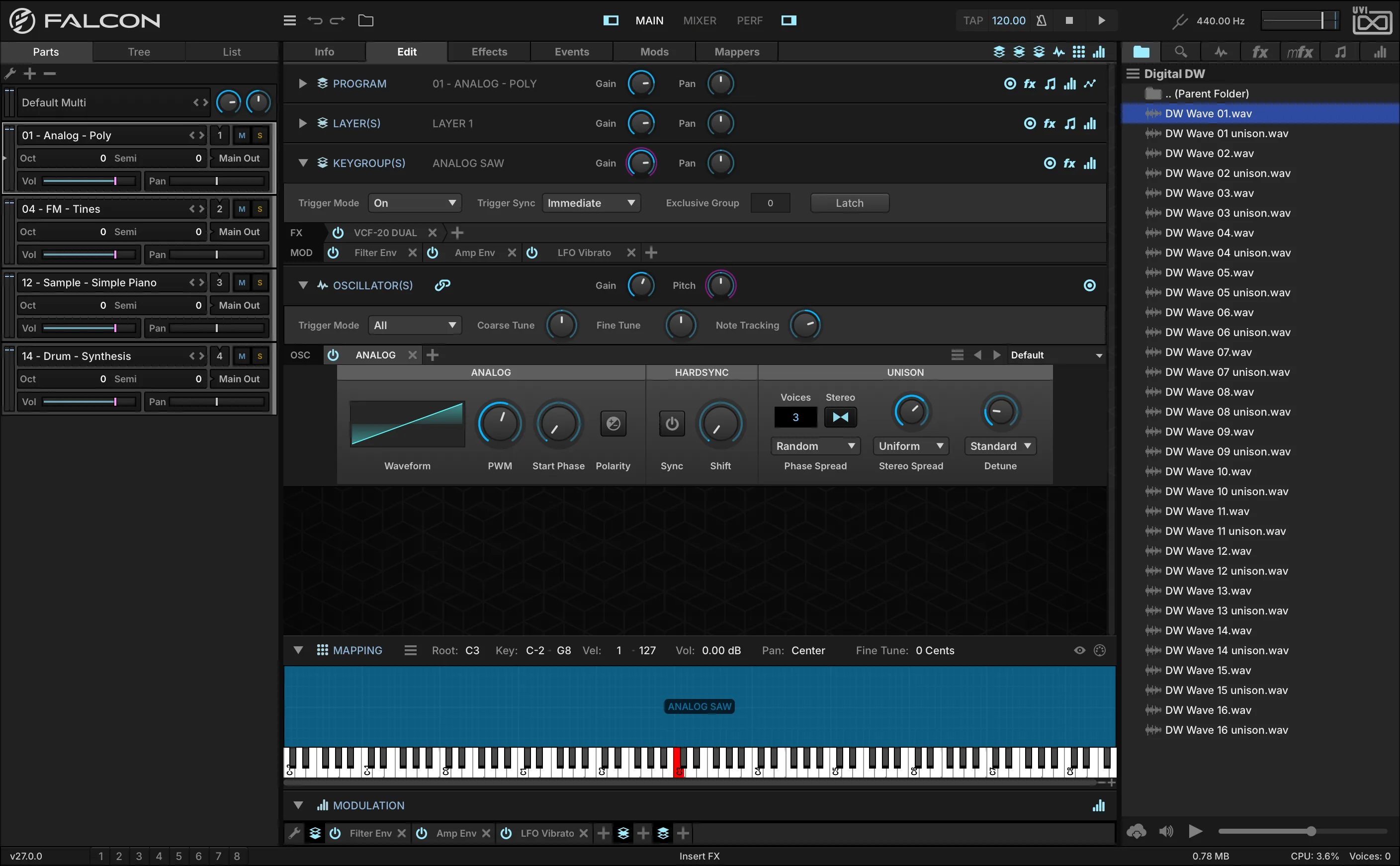
- 1 Main Menu
Opens the Main Menu: loading and saving multis and programs, Undo / Redo / History, UI snapshots, Preferences, and window size. Each command is described under Main Menu below.
- 2 Undo / Redo
Reverts or re-applies the last action. You can step back to any previous state with the History panel (available through the Main Menu).
- 3 Browser Toggle
Click the folder icon to open the Library Browser and view/load instruments, presets, or loops and sounds into the chosen part — the same as double-clicking the part’s program name. See Which Browser?
- 4 Changing the View
The MAIN, MIXER, and PERF buttons change the primary view of the Falcon window. See Main, Mixer and Performance.
- 5 Show/Hide Sidebar
The left and right sidebars can be individually hidden or shown. The left sidebar displays the PARTS, TREE, and LIST editors; the right sidebar displays the sidebar browsers. The left sidebar is shown in Main view only.
- 6 Tempo
Falcon’s current TEMPO, from 10 to 400 bpm. Double-click to enter a value, or click and drag up/down. Every tempo-synced parameter in Falcon follows it. When Sync To Host is enabled, the Tempo cannot be edited manually.
- 7 Tap Tempo
Tap the TAP button repeatedly at a consistent tempo to enter the tempo by feel rather than typing a value.
- 8 Sync To Host / AutoPlay
Enabling SYNC TO HOST causes Falcon to follow an external tempo source — the host application’s tempo when used as a plug-in, or MIDI Beat Clock when standalone. Enabling AUTOPLAY causes Falcon to play and stop along with the host. AutoPlay is not shown in standalone mode. For a loop’s own auto-play, see Parts.
- 9 Play / Stop
The PLAY and STOP buttons manually start and stop Falcon’s playback. When AutoPlay is enabled they also reflect the host application’s transport state.
- 10 Global Tune
GLOBAL TUNE adjusts the tuning for all parts, using the A above Middle C as a reference. Global Tune defaults to 440 Hz, and is adjustable from 392 Hz to 493.88 Hz.
- 11 Global Volume
GLOBAL VOLUME adjusts the output volume for the Main Outs.
Main Menu
The Main Menu opens from the menu icon at the left of the toolbar (1). Point at a command to see what it does.
Status Bar
The status bar is displayed at the bottom of the window and provides quick, at-a-glance information.
- 1 Version
The installed version of Falcon is displayed on the left side of the status bar.
- 2 Workspace
Store and recall the UI settings of the left and center panes as a workspace, up to 8 slots. Click the button to select a workspace; Shift-click to save the current state into a workspace; Shift+Cmd/Ctrl-click to delete the workspace. The number of a saved workspace is lit in blue. NOTE: Workspaces and Snapshots both manage left/center panel state, but they operate independently.
- 3 Hover Help
The center of the status bar displays contextual help as you use Falcon — for example “Global Volume” when hovering over the output volume knob, or “Oscillator tune in semitones” when hovering over the Oscillator module’s Coarse Tune knob.
- 4 Performance Summary
The right side of the status bar displays a performance summary for the current multi: memory usage, CPU usage, and the number of voices currently playing.
Main
The Main view is the primary view for creating and editing parts in Falcon, and the instruments and samples that those parts contain.
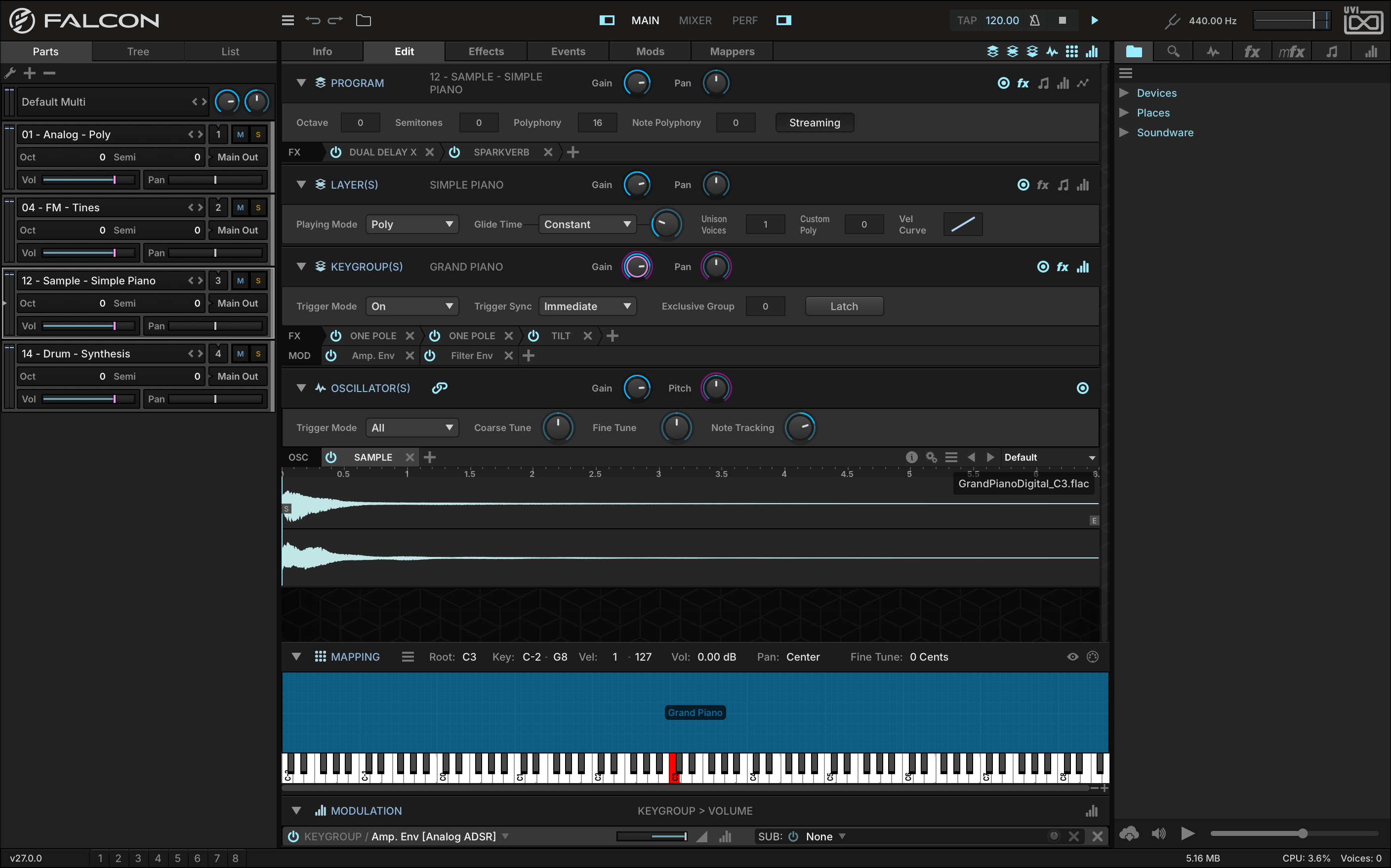
- 1 Toolbar
Always-visible top bar with Main Menu, browser toggle, view selector, sidebar toggles, tempo and transport. See Toolbar for full details.
- 2 Center Pane
Primary working area for viewing and editing parts — the Info, Edit, Effects, Events, Mods and Mappers tabs are displayed here.
- 3 Left Sidebar
The LEFT SIDEBAR hosts the Parts, Tree, and List editors for navigating the multi.
- 4 Right Sidebar
The RIGHT SIDEBAR hosts the sidebar browsers for loading programs, presets and samples.
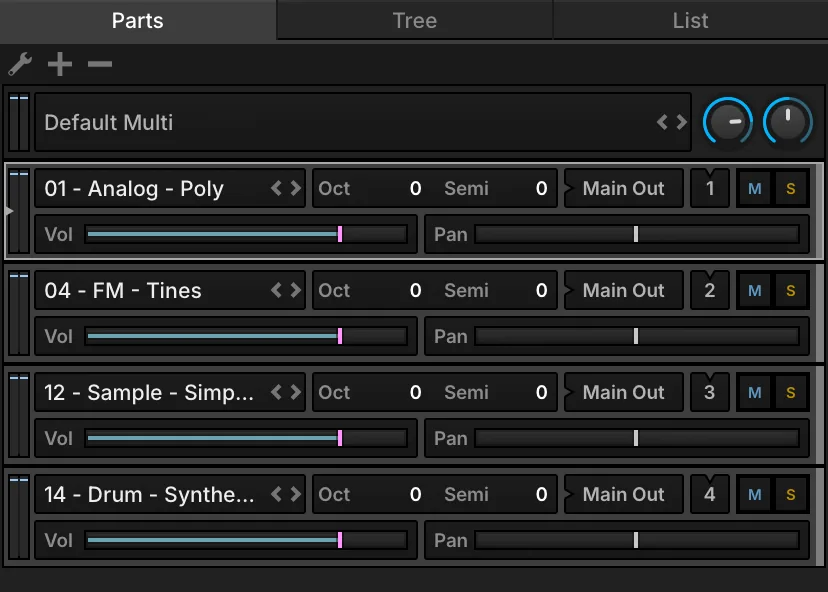
Parts
The Parts List, in the left sidebar, lists every part of the multi and selects the one displayed and edited in the center pane. Part settings are independent of the program loaded in the part, and are saved with the multi — or with your host session when Falcon is used as a plug-in.
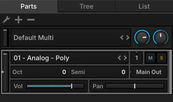
- 1 Parts List menu
Actions for the selected part: Empty selected Part, Load Program in selected Part and New Program in selected Part.
- 2 Add / remove parts
The + and − buttons add and remove parts. To reorder parts, press and hold a part and drag it.
- 3 Multi Controls
The name of the loaded multi. Double-click it to open the File Browser and load a multi, or use the previous/next buttons to step through the multis in the same folder.
- 4 Global Volume / Tune
The same Global Volume and Global Tune as in the toolbar, with the output meters of the Main Out.
- 5 Program name
The loaded program; an asterisk marks unsaved changes. Double-click to open the Library Browser, or Shift-double-click to show it in the FILES tab of the right sidebar — either one opens at the program’s location. Right-click for Empty Part, Delete Part, Duplicate Part, Load Program, Reload Program (discards the changes since the last save) and New Program.
- 6 Previous / Next program
Steps through the programs in the same folder.
- 7 MIDI Input
The part’s MIDI input (A1, A2, …), incremented automatically for each new part. Press and hold to change it; Omni listens on all ports and channels, and shows an asterisk.
- 8 Mute / Solo
Mute or solo the part. Alt/Option-click to mute or solo only that part; Cmd/Ctrl-click to mute or solo every part except the one clicked.
- 9 Output meters / MIDI indicator
The part’s output level. The MIDI indicator flashes whenever the part receives MIDI on its input.
- 10 Octave / Semi
Transpose the part’s incoming MIDI in octaves and semitones.
- 11 Audio Output
The part’s audio output; new parts go to the Main Out. Press and hold to route it to another output.
- 12 Volume / Pan
The part’s output level and stereo placement.
Additional controls on the part row, for loops and for the part color:
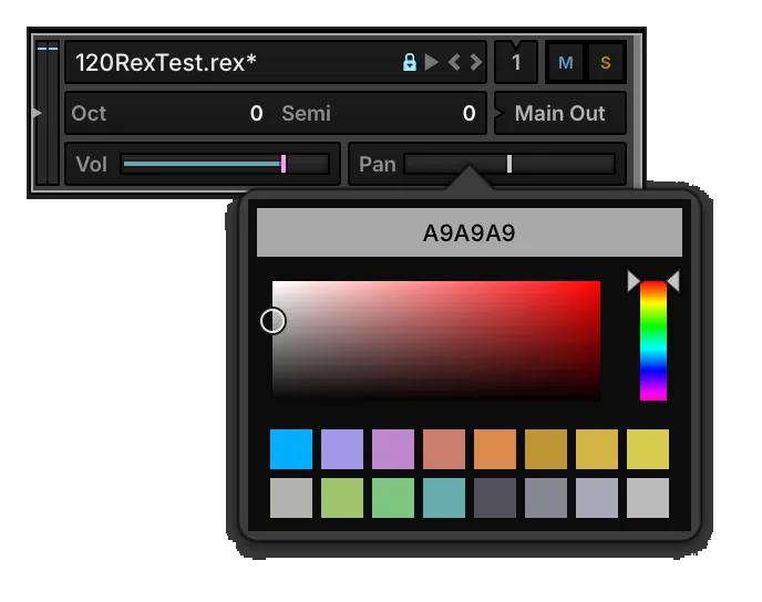
- 13 Unsaved changes
The asterisk after the program name: the program has unsaved changes.
- 14 Auto Play
Triggers the loop when Falcon’s playback starts.
- 15 Play
Lights while the loop is playing, and starts or stops it manually.
- 16 Part color
Click the color bar on the right of a part to choose its color.
Drag the right edge of the Parts List to widen it; the controls rearrange so that more parts fit at once.
Tree
The Tree shows one part as a hierarchy of nodes, following Structure: from its program down to each keygroup and oscillator. Its two sections, INSTRUMENT (the nodes) and INSPECTOR (the details of the selected node), are collapsed or expanded with the arrow left of their name; drag the Inspector’s top edge to change its height.
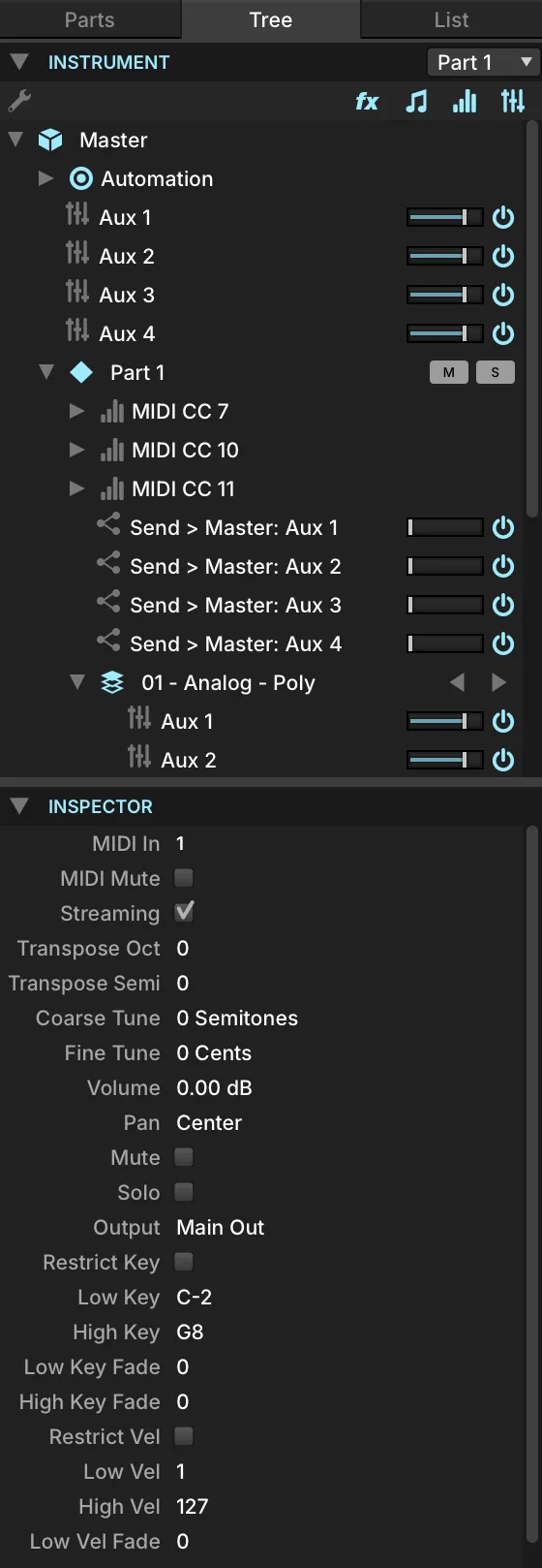
- 1 Instrument
The nodes of a single part, plus a few global nodes. Choose the part from the Part Selector menu in the upper right.
- 2 Node visibility toggles
Show or hide Effects, Event Processors, Modulation Sources, and Aux FX buses and sends. Master, Host Automation, Part, Program, Layer, Keygroup and Oscillator are always shown.
- 3 Navigating the tree
Press a node to select it and show its details in the Inspector. Press the arrow left of a node to expand or collapse it; hold Alt/Option to expand all of its children too.
The node selected in the Tree also drives the other views — the Edit tab, the Effects tab and so on — which makes it the quickest way around the layers, keygroups, effects and modulation assignments of a large program. Double-click a node to jump to its main editor: an effect opens in the Effects tab, a modulation source in the Mods tab.
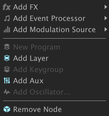
For a node’s options, select it and press the menu icon in the upper left, or right-click the node.
The Inspector lists the selected node’s properties. Double-click a value to type a new one, or drag it up or down. Most properties also appear in other views, such as the Edit tab or the Mixer, but some “under-the-hood” properties are shown only here.
List
The List gives a detailed rundown of one part and its program, in four sections that follow the same hierarchy: Part, Program, Layer(s) and Keygroup(s). Drag its right edge to widen it; each section collapses or expands with the arrow left of its name.
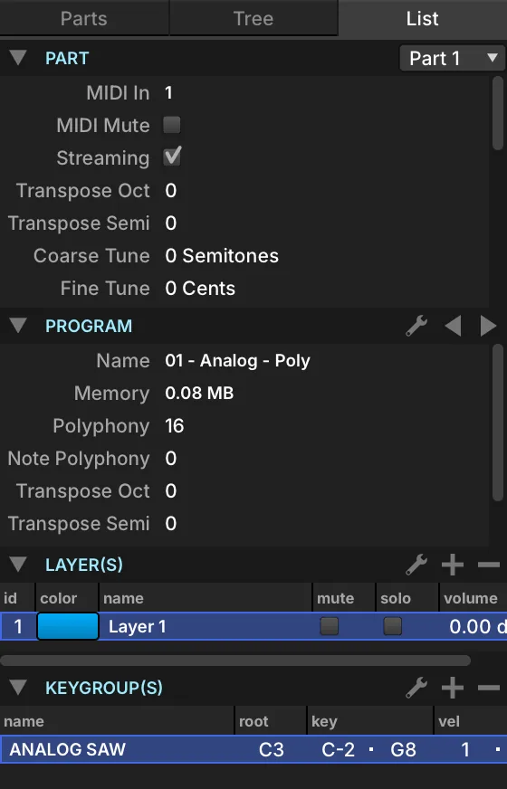
- 1 Part section
The settings of the selected part — the same as in the Parts List.
- 2 Part Selector menu
Chooses which part all four sections show.
- 3 Program section
The settings of the program loaded in the part — the same as the Program section of the Edit tab.
- 4 Program menu
Creates, loads, reloads, saves and protects the program. See Program Menu below.
- 5 Previous / Next Program
Steps through the program files in the current folder.
Layers and Keygroups
The Layers section lists every layer of the program, and the Keygroups section every keygroup of the selected layers. What you select here is what the Edit tab shows, which makes it easy to work on one layer or a few keygroups of a large program.
- Press a name to select it; hold Cmd/Ctrl to select several. Press the empty space below the last row to deselect all — with nothing selected, the Edit tab shows a composite, and edits apply to every layer or keygroup.
- Right-click a column header to choose which settings are shown as columns, and drag a header left or right to reorder the columns. In the Keygroups section, press a column name to sort by it, and press again to reverse the order; drag a column’s right edge to widen it.
- The Layer menu edits layer rules and cuts, copies, pastes and duplicates layers; the Keygroup menu cuts, copies, pastes and duplicates keygroups. See Adding, Moving and Deleting Keygroups.
- The Add and Remove buttons add a layer or keygroup, or remove the selected ones.
Program Menu
The Program section’s menu manages the program file. Point at a command to see what it does.
Info
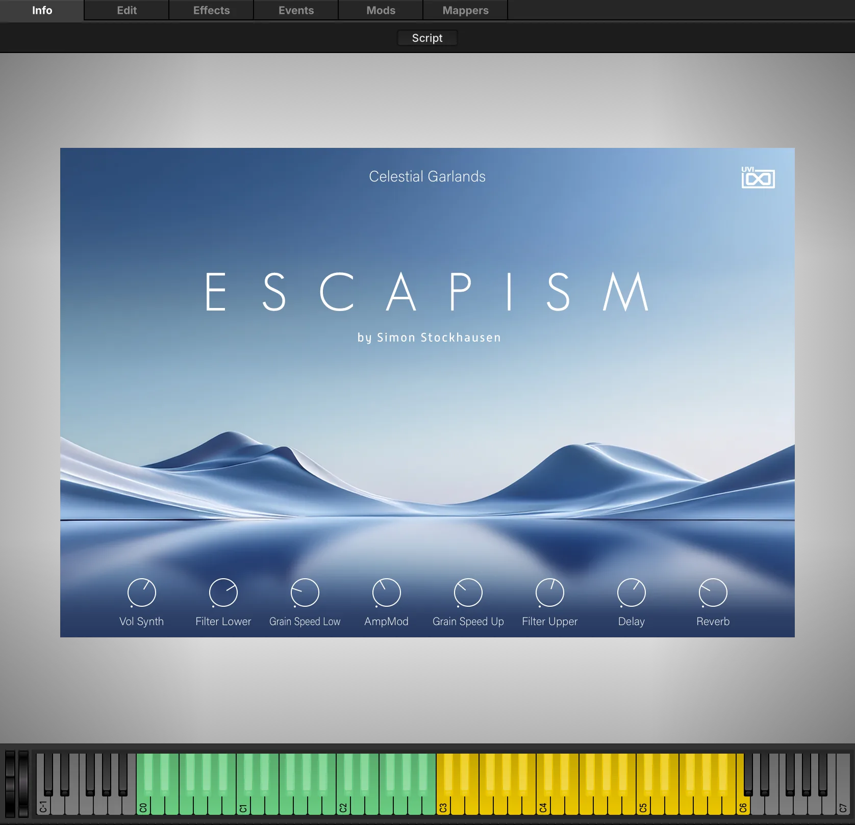
The Info tab is the “front panel” of the selected program: its macros, its description and images, and a playable keyboard.
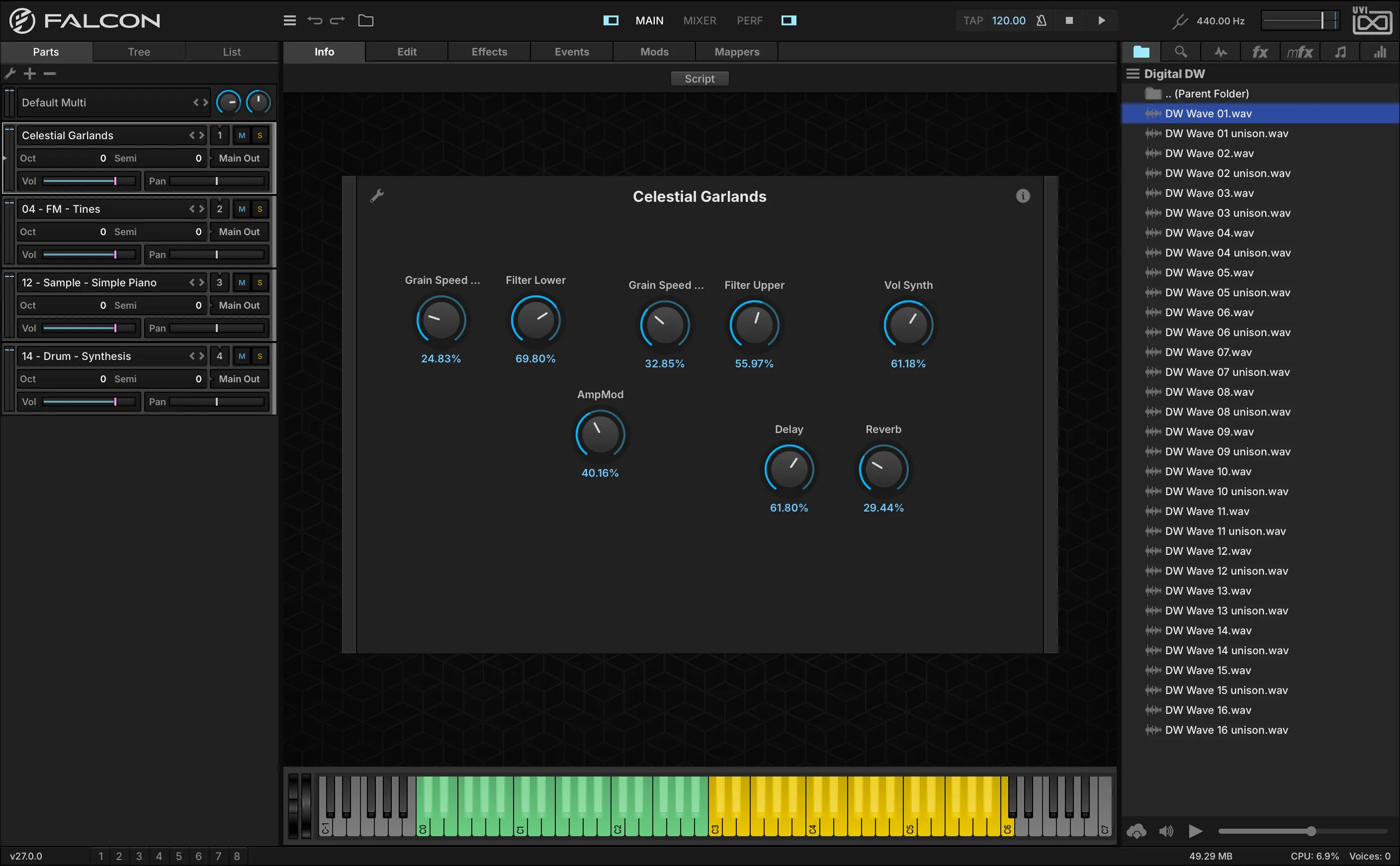
- 1 Script button
When the program’s script defines a custom interface, that interface is shown by default; the Script button switches between it and the standard view.
- 2 Edit Mode
Press EDIT to rearrange the macros: drag a control to move it, double-click a label to rename it, or right-click for more edit commands.
- 3 Program Information (i)
Shows the program’s description — modwheel assignments, what the macros do, playing tips. You can write and save descriptions for your own programs. UVI Soundware programs also show images; when there are several, the < and > arrows cycle through them.
- 4 Macros
The controls assigned to macros, for quick access to the program’s important settings. See Modulators › Macro.
At the bottom of the Info tab, the keyboard plays the program when clicked. The program’s key range is highlighted and the keys outside it are darkened; keys used by keyswitch layer rules are shown in blue. A Script Processor can also set its own key colors.
Edit
The Edit tab is organized into stacked sections — Program, Layer, Keygroup, Oscillator, Mapping Editor and Modulation Editor — that can be individually shown, hidden, collapsed, or expanded. The first four form the program hierarchy: a program contains layers, a layer contains keygroups, and a keygroup contains oscillators. See Structure for details.
- 1 Section Headers
PROGRAM, LAYER, KEYGROUP, OSCILLATOR, MAPPING EDITOR and MODULATION EDITOR. Click the arrow on the left of a header (or double-click the header) to collapse or expand the section.
- 2 Show/Hide Sections
Each section can be shown or hidden using the corresponding buttons in the upper-right toolbar of the Edit tab.
- 3 Parameters View
Each of the four hierarchy sections contains a Parameters view that displays its controls. The parameter view can be shown or hidden by pressing the toggle in the section header.
- 4 Lanes
Additional lanes — Effects, Event processors, Modulation sources, Mapper editors — can be toggled per section using the corresponding buttons in the section header. Each lane is a condensed view of its full tab, showing only modules saved at that level of the program hierarchy.
- 5 Module Tabs
Each module appears as a tab. Click the tab name to show/hide its controls. The POWER button on the left of the tab enables/disables the module; the X button on the right deletes it. Press and hold on the module name to choose another module in its place.
- 6 Add Module (+)
Press the plus (+) button to add a new module to the lane from a menu of available modules. NOTE: For Effects and Event lanes, left-to-right order indicates signal flow. For Modulations and Mappers lanes the order is not significant. See Mods.
Program
The Program Editor configures program-wide playback parameters.

- 1 Gain & Pan
Sets the output level and stereo placement for the entire program. These are distinct from the Part gain and pan settings and are saved with the program.
- 2 Streaming
Toggles whether samples in the program are streamed from disk. When it is off, the program’s samples are loaded fully into memory. See Preferences › Streaming.
- 3 Octave & Semi
Transposes incoming MIDI to the program. OCTAVE shifts in octaves, SEMI in semitones.
- 4 Polyphony
Sets the default number of simultaneous voices available for each layer in the program. To override this on individual layers, see Custom Polyphony in the Layer section. Keeping polyphony as low as practical reduces processing load, especially with per-keygroup effects or modulators.
- 5 Note Polyphony
Sets the maximum number of simultaneous triggers of the same note. A setting of zero is a special value indicating UNLIMITED.
Layer
The Layer Editor configures playback behavior for the selected layer(s).

- 1 Gain & Pan
GAIN and PAN set the output level and stereo placement for the selected layer(s).
- 2 Play Mode
Determines what happens when additional notes are triggered while another note is held. POLY modes play multiple notes simultaneously; MONO modes play only the last triggered note.
- 3 Portamento
With POLY PORTAMENTO or MONO PORTAMENTO there is a glide from the previous note to the new one. GLIDE TIME sets the duration. The glide mode menu next to it chooses Constant (always the same time) or Proportional (longer for wider intervals). MONO PORTAMENTO SLIDE always starts from the pitch of the previous note, even if released first.
- 4 Unison Voices
Sets the number of voices triggered with each note received; the default is 1. When using multiple voices, the Unison modulation sources (External › Other) can modulate parameters per voice — for example Keygroup Pitch or Pan — for a richer sound.
- 5 Custom Polyphony
Sets the maximum polyphony for the layer. A setting of zero is a special value indicating no layer-specific limit (the program polyphony applies).
- 6 Velocity Curve
Maps incoming velocity values. Default is NORMAL (1:1). Right-click to choose Constant velocity (a fixed velocity, double-click to set it) or Velocity Curve, or one of the presets: MAX (always 127), HARD (you must play harder to reach high velocities), NORMAL and SOFT (soft playing already gives high velocities). Drag the curve up or down to shape it, or double-click to enter a value.
The curve displays incoming velocities on the X axis, and triggered velocities on Y. Drag the curve up or down to shape it, or double-click and enter a value:
- Values between -1 and 0 cover the range between the Hard and Normal presets.
- Values between 0 and +1 cover the range between the Normal and Soft presets.
- Values above +1, up to 127, set a constant velocity; exactly +1 is the Soft preset.
Keygroup
The Keygroup Editor configures triggering behavior for the selected keygroup(s).

- 1 Gain & Pan
GAIN and PAN set the output level and stereo placement for the selected keygroup(s).
- 2 Trigger Mode
Determines what event triggers the keygroup. ON: note-on (default). OFF: note-off. OFF + E: note-off, amplitude follows the current envelope level. OFF + V: note-off, amplitude follows the note-off velocity. OFF + VE: combines envelope and note-off velocity. The Off variants help match the amplitude of release samples to the preceding note.
- 3 Trigger Sync
Determines how the keygroup is played back once triggered. IMMEDIATE: triggered immediately. NEXT BEAT: triggered at the start of the next beat. NEXT BAR: triggered at the start of the next bar. The Next Beat/Bar options are useful with tempo-synced event processors such as the Arpeggiator, or with tempo-synced loops.
- 4 Exclusive Group
Marks keygroups as mutually exclusive — the classic use case is a hi-hat group where a closed hi-hat cuts off the open hi-hat. 32 exclusive groups are available per layer. A setting of zero indicates no exclusive group assignment.
- 5 Latch
When LATCH is enabled, notes are held (latched) indefinitely when triggered; to release the note, play the same note again.
Oscillator
A keygroup contains one or more oscillators. The Oscillator Editor sets the playback and pitch parameters common to all oscillator types.
Oscillators are chosen from a single panel that drops from whichever control opened it. Press the + button on the oscillator bar to add one, or press and hold — or right-click — an oscillator slot to replace what is already in it. The same panel opens from the Tree view, by right-clicking a keygroup and choosing Add Oscillator….
The panel lists every oscillator in columns under its category heading, SAMPLING and SYNTHESIS, each entry an icon and a name. The oscillator the slot already holds is highlighted. A card along the bottom describes whichever entry the pointer is on — its icon, its name, its category and a one-line description — and falls back to the current oscillator when the pointer leaves the list.

- 1 Edit All Oscillators
With EDIT ALL OSCILLATORS enabled, the parameters below are edited simultaneously for every oscillator in the keygroup. Disable to edit each oscillator individually by selecting its tab.
- 2 Trigger Mode
When the keygroup contains multiple oscillators, TRIGGER MODE chooses which is triggered. ALL: every oscillator on every note. CYCLE: round-robin in fixed order — with oscillators A, B and C the order is always A-B-C, A-B-C. RANDOM CYCLE: each oscillator triggers once per cycle in random order, with no direct repeats across cycles — B-A-C, A-C-B, then C-B-A. RANDOM: a single random oscillator each note — A-C-C-B-A-B-B-C-A.
- 3 Gain
Sets the output level for the selected oscillator(s) within the keygroup.
- 4 Coarse / Fine Tune & Pitch
COARSE TUNE and FINE TUNE set the oscillator’s pitch in semitones and cents — static, not modulatable. The PITCH control can be modulated and covers ±4 octaves. Typical use: Fine Tune to correct a sample, Coarse Tune to shift up/down the keyboard, Pitch to modulate with an LFO or envelope.
- 5 Note Tracking
Determines how incoming notes are transposed. 100% transposes 1:1 relative to the root key. 200% doubles the transposition (G4 root, G#4 played → sounds like A4). Negative values invert (-200%, G#4 → sounds like F4). 0% gives a constant pitch regardless of note.
Sample Editor
For sample-based oscillator types, the Sample Editor displays a waveform editor and additional controls specific to audio files and loops. (For synthesis oscillators, see Oscillators.).

- 1 Waveform Display
The waveform of the loaded sample, zoomed to fit by default. If the oscillator has no sample, drop one here from the FILES tab of the right sidebar or from the Finder (Mac) / File Explorer (Windows). Hold Alt/Option while scrolling to zoom horizontally, Shift to zoom vertically. Drag the display’s bottom edge to make it taller; its width follows the center pane, so drag the sidebar border to widen it.
- 2 Time Ruler
The duration of the sample. Right-click the ruler to switch its format between Samples, Beats and Seconds.
- 3 Sample Info
Overlays details about the loaded sample on the waveform: file location, bit depth, sample rate, number of channels, duration and file size, plus the loop details if the sample is looped.
- 4 Parameters
Shows or hides the parameters specific to the oscillator type. See Oscillators.
- 5 Start / End Markers
Drag the S and E markers, at the left and right edges of the waveform, to set where playback begins and ends within the file.
Editing
To edit the sample, click and drag to select a time range, then right-click for the editing commands: CUT, COPY, PASTE, UNDO, REDO, SELECT ALL, DESELECT ALL, CROP, DELETE, NORMALIZE, SILENCE, REVERSE, FADE IN, FADE OUT, PLAY SELECTION, SNAP SELECTION TO NEAREST ZERO-CROSSING, SET START MARKER USING CURRENT POSITION and SET END MARKER USING CURRENT POSITION. The same menu also holds a Zoom submenu and REVEAL IN FINDER (Mac) / REVEAL IN EXPLORER (Windows).
CHANGE PLAYING DIRECTION TO REVERSE plays the sample backwards; CHANGE PLAYING DIRECTION TO FORWARD restores it. SET AS ONE SHOT plays the entire sample on every trigger, whatever the keygroup’s amplitude envelope — a natural fit for drums and percussion; DISABLE ONE SHOT returns to standard playback.
To apply one of Falcon’s effects to the sample permanently, select some audio, choose APPLY FX, choose the effect, set its parameters and press OK. The effect is rendered into the sample, not applied in real time. Save the sample to keep the result, or choose Undo to discard it.
When several keygroups are selected, a Batch menu appears, which applies an action — normalizing, applying an effect — to every selected keygroup at once.
Looping
To add a loop, select part of the sample, choose CREATE LOOP and pick a loop type:
- FORWARD: the looped section plays forward; when playback reaches the loop end, it resumes from the loop start.
- ALTERNATE: the looped section plays alternately forward (loop start → loop end) and in reverse (loop end → loop start).
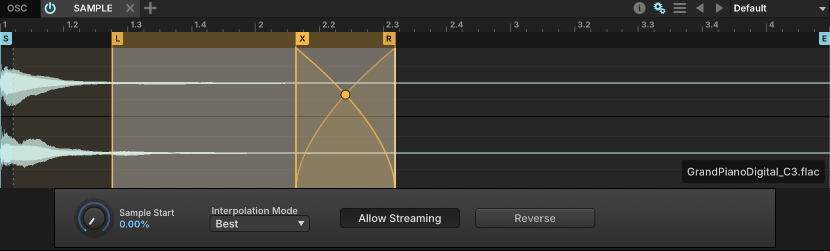
- 6 Loop Markers (L / R)
Drag the L and R markers to set where the loop begins and ends.
- 7 Loop Crossfade (X)
Crossfading the looped section makes a loop sound less looped and smooths out clicks at the loop point. ENABLE XFADE turns the crossfade on, DISABLE XFADE off; while it is on, drag the X marker to set the length of the crossfade, and drag the point on the crossfade curve to shape it. PRINT CROSSFADE writes the crossfade into the sample.
- 8 Looped Release
What happens when a note is released. ENABLE LOOPED RELEASE: the loop keeps playing until the release phase is over. DISABLE LOOPED RELEASE: playback continues past the loop end until the release phase ends or the end marker is reached. DELETE LOOP removes the loop.
Saving Samples
On sampling oscillators, the module’s Preset File menu (see Module Preset Menu) adds commands for the sample itself:
- SAVE SAMPLE: saves the sample file in place.
- SAVE SAMPLE AS…: saves the sample to a new file.
- SAVE SAMPLE WITH PLAYBACK OPTIONS: saves the sample file in place, and writes the sample and loop start/end markers into it.
- SAVE SAMPLE AS WITH PLAYBACK OPTIONS…: saves the sample to a new file, with the sample and loop start/end markers written into it.
To reveal the sample file on disk, right-click the sample and choose REVEAL IN FINDER (Mac) / REVEAL IN EXPLORER (Windows).
Mapping
The Mapping Editor displays the arrangement of the program’s layers and keygroups. A program can contain anything from a single keygroup in a single layer covering the entire key and velocity range, to many layers each holding dozens of keygroups assigned to very small ranges.
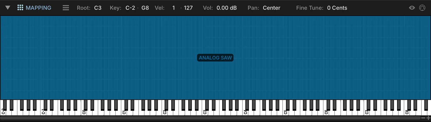
- 1 Mapping area
The key range runs horizontally and the velocity range vertically. Each keygroup is a block covering its key and velocity range; when the program has several layers, they are stacked on top of each other.
- 2 Selection details
Root key, key range, velocity range and other details of the selected keygroups. Edit them in the usual manner — double-click to type a value, or scroll. With several keygroups selected, an edit applies to all of them.
- 3 Mapping menu
Opens the Mapping Editor’s menu of edit commands, also available by right-clicking anywhere in the mapping area. See Adding, Moving and Deleting Keygroups.
Pressing a key on the piano keyboard triggers the note, and plays any keygroup assigned to that key. The vertical position sets the velocity: press closer to the bottom of the key for higher velocities, closer to the top for lower ones.
To adjust a keygroup’s key or velocity range, select it, then click and drag any of its edges. Hold Cmd/Ctrl before you start dragging to fade the range instead; a dashed line inside the keygroup marks where the fade begins.
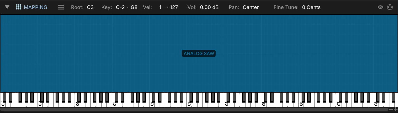
- 4 Navigation toggles
HIGHLIGHT PLAYED KEYGROUPS flashes keygroups as they are triggered; MIDI SELECT selects them as they are triggered.
- 5 Importing samples
Drag one or more samples from the FILES tab of the right sidebar or from your desktop to create keygroups. Where you drop sets the new keygroup’s key range: the closer to the top of the velocity range, the wider the key range. Hold Alt/Option while dragging to open the custom import dialog instead.
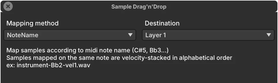
MAPPING METHOD chooses how each file is assigned — NOTE NAME, BLACK KEYS and others, many of them read from the file name or other metadata — and describes the selected one. DESTINATION LAYER picks the layer that receives the samples, or a new one.
- 6 Zoom and resize
Zoom horizontally with the + and − buttons in the lower right, or resize the editor vertically by dragging the Mapping Editor toolbar up or down.
Adding, Moving and Deleting Keygroups
The Mapping Editor’s menu holds all of its edit commands. To open it, right-click anywhere in the mapping area, or press the menu button towards the left end of the Mapping Editor toolbar. Point at a command to see what it does.
Keygroup Templates
A keygroup template is a snapshot of a keygroup in its entirety, including all of its oscillators, effects and modulators — a starting point for new patches, or a shortcut when building complex parts.
To create one, select the keygroup in the Mapping Editor and choose Save Keygroup Template from the Mapping Editor’s menu. Name the template and click Save. To overwrite an existing template, save it again under the same name.
The new template is offered in the Create Keygroup and Create Keygroup in New Layer submenus, and can be added to any program from there.
- A template always holds exactly one keygroup: several keygroups cannot be saved into one template, nor saved as templates in one operation.
- If Save Keygroup Template is grayed out, select the keygroup in the Tree instead.
- To rename, organize or share your templates, open the folder where they are saved:
~/Documents/UVI/Falcon/User Presets/Keygroups.
Layer Rules
Layer Rules dynamically change which of a program’s layers a note triggers — to switch between legato and staccato articulations, for example, or to cycle through several variations of the same note for a more realistic performance.
To open the Layer Rules Editor, choose Edit Layer Rules (Cmd/Ctrl+E) from the Mapping Editor’s menu. The rules are listed on the left, and the program’s layers under Targets on the right.

- 1 Root Rule
The rule every sub-rule belongs to. Right-click it to add a sub-rule, or to delete the rule.
- 2 Rule Type
What the root rule uses to choose between its sub-rules — here, Key Switch. The menu is available once the rule has sub-rules; each type is described below.
- 3 Sub-rules
One per layer or group of layers, each with the condition that selects it — here the key switch notes C0 and D0. Select a sub-rule to set its condition and its targets.
- 4 Learn
Key Switch rules only: listens for the next note you play and uses it as the sub-rule’s key switch.
- 5 Condition
Sets the sub-rule’s condition — for a Key Switch rule, the note. Its value is shown in the sub-rule’s name.
- 6 Targets
The program’s layers. Tick the ones the selected sub-rule triggers: here the C0 sub-rule plays the Sustain layer, and D0 plays Staccato.
- Click No rule, right-click to add a new rule and choose Add root rule.
- Right-click the root rule and choose Add sub-rule, once for each layer or group of layers the rule chooses between.
- Choose the root rule’s type (see below), such as Key Switch. The type menu is available once the rule has sub-rules.
- Select each sub-rule, set the condition that triggers it, and choose its layers under Targets.
For example, a Key Switch rule with two sub-rules, the first set to C0 and the second to D0, plays the first sub-rule’s layers after C0 is pressed and the second’s after D0.
Sub-rules can have sub-rules of their own, which branch the triggering logic further. To remove a rule, right-click it and choose Delete rule.
| Rule type | Each sub-rule is triggered by |
|---|---|
| Key Switch | A key switch note. Learn sets it from the next note you play. |
| MIDI CC | A range of values of the controller chosen for the root rule. |
| Pitch Bend | A range of pitch bend values. |
| Speed | A range of time since the previous note-on, in hundredths of a second (0–100, so up to 1 s; longer gaps count as 100). |
| Note Duration | A range of note durations. |
| Cycle | Its turn: the sub-rules play one after the other (round robin). |
| Random | Chance: one sub-rule is picked at random for each note. |
| Random Cycle | Chance, without repeats: every sub-rule plays once, in random order, before any plays again. |
| Legato | A legato level: the interval, in semitones, from the held note to the new one. Level 0 plays notes that are not played legato. |
Effects
The Effects tab displays every audio effects path, from the effects on the master output down to those on a single keygroup. Within one node, effects process from top to bottom. Between levels, audio flows up, from the keygroup to the master. See Structure. For each effect, see Effects.

- 1 Navigation breadcrumbs
Choose which effects path you are viewing. Press a node’s name to show its effects, or the arrow to its right to go to one of its child nodes — for example, one of the program’s layers. Selecting a node in the Tree does the same.
- 2 Aux Sends
With the aux FX nodes shown in the Tree, each node that has aux sends shows them: send level, mute, and pre/post-fader for each aux bus.
- 3 Preset Browser
Drag an effect from the FX tab of the right sidebar into the chain to add it.
- 4 Tempo Sync
Effects with time-based parameters, such as delays or tremolo, show a TEMPO SYNC button next to the Preset File menu, which locks them to Falcon’s tempo; their time settings then read in note and bar values.
- Add an effect with the + button in the upper right, or by dragging it from the FX tab of the right sidebar.
- Reorder effects by pressing and holding an effect’s header and dragging it to a new position.
- Replace an effect by clicking its name and choosing another from the menu.
- Enable or disable an effect with the POWER button left of its name, and delete it with the X button at the far right.
- The Modulation and Keyboard sections can be shown or hidden with the buttons in the top right.
Aux FX
There are two aux effects sections, each with at least four independent aux buses:
- Master aux FX, fed by sends on each part of the multi; saved with the multi.
- Program aux FX, fed by sends on each layer and keygroup of the program; saved with the program.
To view and add aux effects, choose the aux bus from the navigation menu of the Program or Master node. The master aux FX and their sends also appear in the Mixer.
To add an aux bus, right-click the Program or Master node in the Tree and choose Add Aux. The new bus comes after the existing ones, and each layer and keygroup of the program (each part of the multi, for a master aux) gets a send to it. To remove an aux bus, right-click it in the Tree and choose Remove Node, or select it and press Delete; its sends are removed with it. Each section keeps at least four aux buses, and a send cannot be removed on its own. Aux buses are named by position (Aux 1, Aux 2, …), so removing one renumbers the buses after it. Both edits can be undone. In the List, the Keygroups section has a program aux send column for each program aux bus.
A program saves only the aux buses that hold effects, with their sends; when it is loaded, they return to their positions, and empty buses are added back up to four. A multi saves all of its master aux buses.
Multi FX
A Multi FX preset saves and recalls all the effects of the current node as one group, so a complex chain can be recalled instantly. Multi FX presets are saved and loaded from the Multi FX preset menu, and its POWER button enables or disables all of the node’s effects together. Clear Multi FX in the Multi FX preset menu removes all of the node’s effects.
Events
The Events tab displays every MIDI event processing path, from the master event processors down to those on a single layer. Event processors are not added to keygroups, since they generally address events that span several keygroups. Signal flows from top to bottom. For each event processor, see Event Processors.

- 1 Navigation breadcrumbs
Choose which event path you are viewing. Press a node’s name to show its event processors, or the arrow to its right to go to one of its child nodes — for example, one of the program’s layers.
- 2 Tree navigation
Selecting a node in the Tree also shows its event processors.
- 3 Preset Browser
Drag an event processor from the EVENT tab of the right sidebar into the chain to add it.
- 4 Modulation / Keyboard Sections
Show or hide the Modulation and Keyboard sections.
- 5 Add Event Processor (+)
Adds an event processor, chosen from the menu.
- Reorder event processors by pressing and holding a header and dragging it to a new position.
- Replace an event processor by clicking its name and choosing another from the menu.
- Enable or disable an event processor with its POWER button, and delete it with the X button in its toolbar.
Modulation
The Modulation Editor displays modulation assignments and sources, and is the central place for editing modulation generators.

- 1 Selected parameter
When you select a parameter, its node and name appear here. For example, selecting the layer gain knob displays “Layer > Volume”.
- 2 Modulation Assignments
The top half of the editor lists every modulation assignment of the selected parameter.
- 3 Modulation Source Editor
The bottom half displays the controls of the selected modulation source.
- 4 Show/hide source editor
Shows or hides the Modulation Source Editor.
Modulation flows from the top of the hierarchy (Master) down through the Part, Program, Layer and Keygroup levels to the oscillators. A modulation generator created at the Master level can therefore target any parameter of the Falcon instance, while one created at the Keygroup level only reaches parameters within its own keygroup. See Structure.
Understanding Modulation Sources
A modulation source generates a control signal that modifies other controls; on its own, it does not affect Falcon’s output. It only has an effect once it is assigned to a control, and where it sits in Falcon’s hierarchy determines which controls it can be assigned to.

- 5 Assignment tabs
A parameter can have any number of modulation assignments. Enable or disable each one with the POWER button on the left of its tab, or remove it with the X button on the right.
- 6 Source name
The node, name and type of the modulation source — for example, “Keygroup > Amp. Env DAHDSR” for a keygroup DAHDSR envelope named Amp. Env. Press and hold the name to choose a different source.
- 7 Ratio
How much the source affects the parameter: +1 to −1 (+100 % to −100 %) for most parameters, +48 to −48 semitones for pitch.
- 8 Invert
Flips the modulation range. For custom shapes, use the Modulation Mapper Editor (below).
- 9 Sub-Modulation
Every assignment has a SUB-MODULATION source that modulates the primary source’s ratio. It is enabled, removed, replaced and scaled the same way as the primary source. For example, an LFO on an oscillator’s pitch with the mod wheel as sub-source gives a vibrato whose depth follows the mod wheel.
Assigning Modulation, MIDI and Automation
Right-click any parameter to assign it a modulation source, a MIDI controller, a macro or a host automation slot. Point at a command to see what it does.
Assigns a MIDI CC to the parameter: choose one from the window that opens, or move the control on your MIDI controller. Choose Clear in that window to remove the assignment.
A few parameters can be automated but not modulated. Right-clicking one of them opens the MIDI/AUTOMATION CONTROL dialog instead, where a MIDI or host automation source can be assigned.
Modulation Mapper Editor
The Modulation Mapper Editor sits between the source and the parameter it modulates, and remaps the control signal to the mapper’s shape.
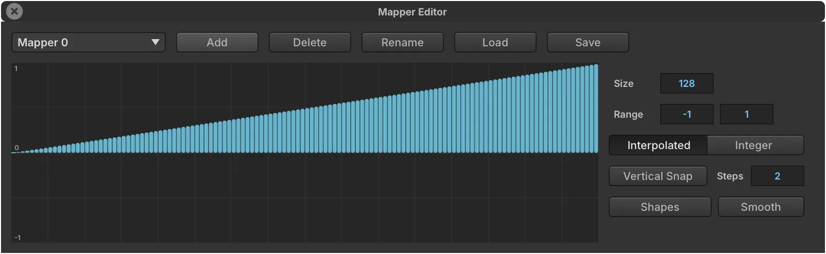
- 10 Mapper editor
Without a mapper, the source is mapped to the parameter 1:1, shown as a linear ramp from the lowest value to the highest.
- 11 Mapper selector
Choose an existing mapper from the menu, or press ADD to create one. Mappers can also be loaded from and saved to disk, renamed and deleted.
- 12 Size and Range
SIZE sets the horizontal axis of the graph, RANGE the vertical axis.
- 13 Drawing the shape
Click and drag in the graph to draw the shape. Hold Alt/Option to draw a straight line, or right-click for preset shapes and functions.
- 14 Interpolated
When enabled, the mapper moves smoothly from one value to the next; when disabled, it jumps, which gives a stair-stepped result.
- 15 Integer
Constrains the mapper’s output to integer values.
Modulation Source Editor
The Modulation Source Editor displays the controls of the selected modulation source or sub-source; each source type is described in Modulators. Its toolbar adds a few controls for moving between sources.

- 16 Modulation Quick View
Opens a menu to browse, select and create modulators, in three sections — Keygroup, Layer and Program, top to bottom — each with its own Add New submenu.

- 17 Modulation ribbon
Every modulator of the selected keygroup, layer and program, left to right, marked with the hierarchy icons. Browse, select, toggle, create and delete modulators here; hover over the ribbon and use the scroll wheel to move along it. A source added with + is not assigned to anything yet: assign it from a parameter’s right-click menu.
- 18 Tempo Sync
Shown for modulators that support TEMPO SYNC: the metronome icon locks the modulator to Falcon’s tempo, and its time settings then read in note and bar values.
Mods
The Mods tab displays every modulation source, from the master modulation sources down to those of a single keygroup. For each modulation source, see Modulators.

- 1 Navigation breadcrumbs
Choose which modulation sources you are viewing. Press a node’s name to show its sources, or the arrow to its right to go to one of its child nodes.
- 2 Tree navigation
Selecting a node in the Tree also shows its modulation sources.
- 3 Preset Browser
Drag a modulation source from the MOD tab of the right sidebar to add it.
- 4 Tempo Sync
Sources that can follow the tempo, such as an LFO’s rate, show a TEMPO SYNC button next to the Preset File menu.
- 5 Power / Rename
The POWER button left of the name enables or disables the source; the X at the far right deletes it. Double-click the name to rename it — descriptive names such as “Amp. Env.” and “Filter Env.” help tell sources of the same type apart.
- 6 Modulation / Keyboard Sections
Show or hide the Modulation and Keyboard sections.
- Add a modulation source with the + button in the upper right, or by dragging it from the MOD tab of the right sidebar.
- Replace a source by clicking its name and choosing another from the menu.
- Assign a source by right-clicking a control and choosing it under Add Modulation; existing sources are listed first, and a new one can be created on the spot. See Assigning Modulation, MIDI and Automation.
Mappers
The Mappers tab displays all modulation mappers of the program. How a mapper reshapes a modulation is described under Modulation Mapper Editor.

- 1 Navigation breadcrumbs
Press a node’s name to show its mappers. Unlike the other tabs, the Mappers tab has no arrow to go to a child node.
- 2 Tree navigation
Selecting a node in the Tree also shows its mappers.
- 3 Adding mappers
Press the + button in the upper right to add a mapper, or drag one from the sidebar browsers. Each mapper is enabled or disabled with its POWER button, and deleted with its X button.
Which Browser?
Falcon loads programs, multis, samples and presets from several places. This manual calls them:
| Name | What it is |
|---|---|
| Library Browser | The LIBRARY tab of the browser window. Opens with the Browser Toggle in the toolbar, or by double-clicking a program name or an empty part. |
| File Browser | The FILES tab of the same window: your disks, favorite places and Soundware. |
| Sidebar browsers | The tabs of the right sidebar: FILES, SEARCH, OSC, FX, MULTIFX, EVENT and MOD. Shift-double-click a program name to show it in the FILES tab. See Sidebar Browsers. |
| Module preset menu | The preset controls in the upper right of each module. See Module Preset Menu. |
Library Browser
The Library Browser searches, previews and loads presets and sounds from your UVI Soundware and Falcon expansions, and from your own files.
To open it, press the Browser Toggle in the toolbar, double-click a program name or an empty part in the Parts List, Mixer or Performance view, or choose Load Program from the Main Menu. The LIBRARY tab searches your Soundware and expansions; FILES switches to the File Browser.

- 1 Library
Searches your UVI Soundware and Falcon expansions.
- 2 Files
Switches to the File Browser, for your own files and folders.
- 3 Search
Type a search term; the matching results appear under PRESETS. The buttons at the far right switch between searching presets (keyboard icon) and sounds (waveform icon), and the star shows only your favorites.
- 4 Presets
The results. Double-click a preset to load it. Click the NAME column to reverse the sort order; right-click the column headers to add or remove columns.
The tags in three tiers — TYPE, TIMBRE and SOUNDWARE — narrow the results; click a tier’s title to expand or collapse it. The INFO panel shows details about the selected result, with the AUTOPREVIEW switch, the preview volume, and AC (auto-close), which closes the browser once a preset is loaded.
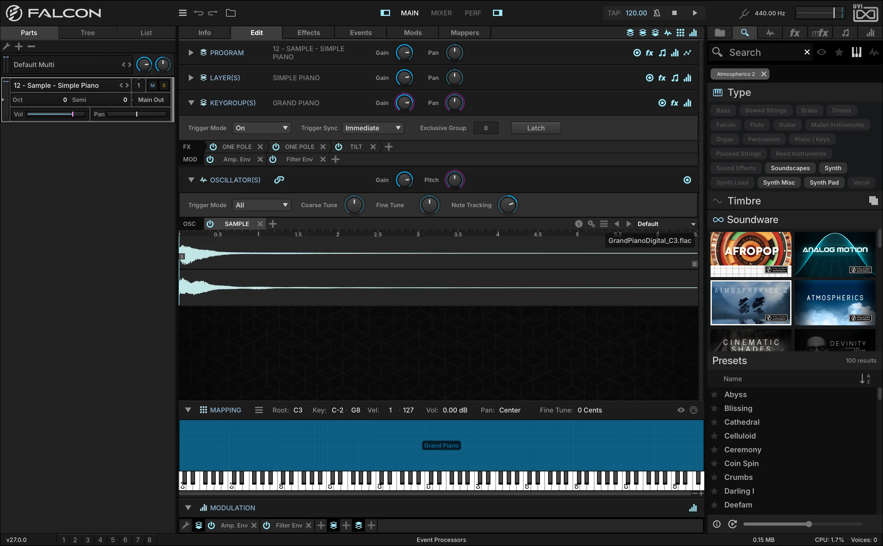
File Browser
The File Browser browses, searches, auditions and loads files: programs, loops and samples, and multis when it is opened to load a multi. The FILES tab of the right sidebar works the same way in a single column, for quick drag-and-drop of any file type (see Sidebar FILES Tab).
Browsing Files
The File Browser is the FILES tab of the browser window: open the Library Browser and click FILES. Its sidebar lists DEVICES — every disk and volume, network volumes included — PLACES, your favorite folders, and SOUNDWARE, every mounted Soundware.
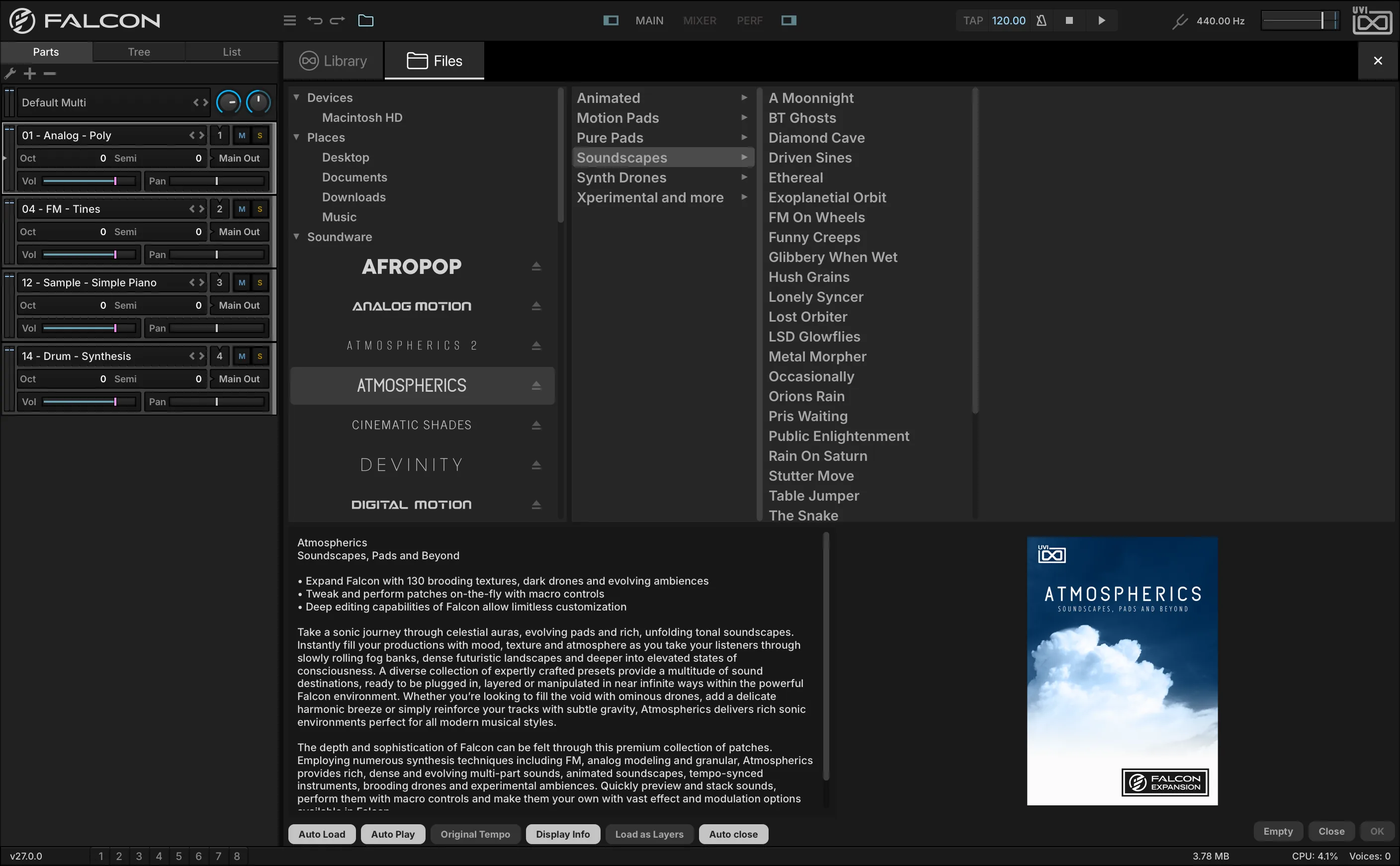
- 1 Library
Switches back to searching: instead of browsing a location, you type a search term and get matches from every indexed location. See Search below.
- 2 Soundware
Every mounted Soundware, whether mounted on demand or at startup (see Preferences › Soundware). Right-click a Soundware’s name for VERIFY SOUNDBANK INTEGRITY, where available: it checks that the file was not corrupted while being downloaded or moved between disks.
- 3 Original Tempo
Auditions an audio file at its original tempo rather than at Falcon’s current tempo.
- 4 Display Info
Shows or hides the panel in the lower half of the browser, with information about the selected file.
- 5 Load as Layers
Adds each program you load to the current one as new layers, leaving the current program’s effects, modulators and so on untouched — for example, to gather several articulations of an instrument in one part and switch them with layer rules. When disabled, a loaded program replaces the current one.
- 6 Auto Close
Closes the browser when OK is pressed or a file is double-clicked. Otherwise it stays open until you press CLOSE or Escape.
Choose a location in the sidebar to display its contents; files and subfolders open in columns to the right. To load the selected program or audio file, double-click it or press OK. You can also drag a file onto a part in the Parts List, or below the last part to load it into a new part. CLOSE or Escape closes the browser without loading; EMPTY unloads the program or sample of the selected part.
AUTO LOAD loads the audio file selected in the browser into the selected part; AUTO PLAY plays it, to audition it without loading.
Right-click a file or folder on disk to REVEAL IN FINDER (Mac) / REVEAL IN EXPLORER (Windows); a file you can write to also offers DELETE FILE.
Search
Instead of navigating to a folder, you can search for files matching your criteria. The locations searched are the folders marked INDEXED in Preferences › Soundware.
Results appear as you type, in four types:
- INSTRUMENTS: program files;
- LOOPS: looped audio samples;
- SOUNDS: non-looped audio samples;
- FAVORITES: presets and sounds tagged as favorites.
Highlight SEARCH in the sidebar to see all types at once, or a type’s name to see only that type; you can switch between types after entering a term, and typing more words narrows the results. Besides the name, the results can show the type, tags, fav, folder and volume (the Soundware) columns: right-click a column header to choose the columns shown, and drag a header to reorder them. Press a column name to sort by it, and press again to reverse the order. To clear the results, delete the search term, or close the browser.
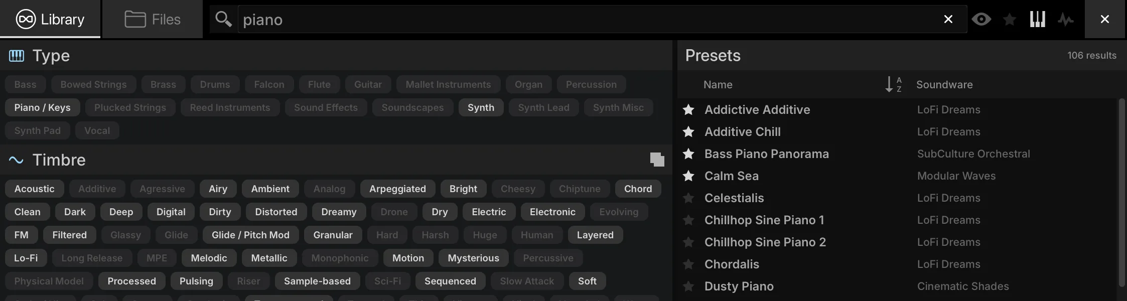
Loading a Multi
To load a multi, double-click the multi name in the Parts List, or choose Load Multi from the Main Menu. The File Browser then loads only multis. Loading a multi clears the current one and replaces all of its settings, unless APPEND MULTI is enabled: the loaded multi’s parts are then added to the current multi, leaving its master effects, modulators and so on untouched.
Sidebar FILES Tab
The FILES tab of the right sidebar is one of the sidebar browsers, shown in the Main, Mixer and Performance views; show or hide the sidebar with its toolbar button, and drag its left edge to resize it. It works like the File Browser, in a single column: expand or collapse a folder with the arrow left of its name, or double-click it to go one level down, and double-click .. (Parent Folder) to go back up. The sidebar menu button opens a menu of your Soundware, Places and Devices, and of the path from the current folder up to the top; choose / to return to the top level. In the SOUNDWARE section, click a Soundware’s name to expand or collapse its contents.
For auditioning, AUTO PLAY plays audio files as they are selected, the PLAY / STOP button next to it starts and stops playback manually, and the VOLUME slider sets the playback level. AUTO LOAD loads the selected sample into the selected keygroup — handy to swap the sample of a keygroup whose key and velocity ranges are already mapped.
Favorites
Presets and sounds can be tagged as favorites, and folders you use often can be added to Places.
- Presets and sounds: right-click a file inside a Soundware, in the File Browser or the sidebar FILES tab, or any file in the search results, and choose Add to favorites; a ★ appears next to its name. Remove from favorites removes the tag. Your own presets and sounds are tagged from the search results, so their folder must be indexed (see Preferences › Soundware). To list your favorites, sort the search results by the fav column.
- Favorite Places: right-click a folder on disk in the sidebar FILES tab (under Devices or Places) and choose Add to Favorite Places; it then appears under Places in every browser. You can also drag a folder onto the Places section. Remove from Favorite Places removes it.
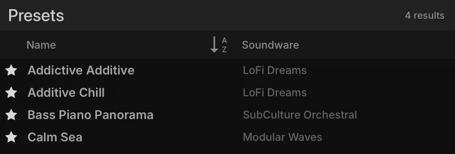
Sidebar Browsers
The sidebar browsers, in the right sidebar, browse and load files and the presets of each module type. Show or hide them with their toolbar button, and drag their left edge to resize them. Each is a tab, from left to right:
- FILES — the file system (see Sidebar FILES Tab).
- SEARCH — the library search
- OSC — oscillators
- FX — effects
- MULTIFX — multi effects
- EVENT — event processors
- MOD — modulation sources
Each tab lists the modules of its type and, under each module, its factory and user presets, organized in folders nested as deep as needed.
The OSC and FX tabs draw that list as a tree, with a search field and a row of category buttons above it. Typing narrows the tree to the modules that match, and the match is made against more than the module name: every module carries its own keywords, so searching for “chorus” also reaches Thorus and “granular” reaches Grains. The category buttons filter the tree as well, and more than one can be active at once — Sampling and Synthesis on the Osc tab, and Delay, Reverb, Modulation, Filter, Equalizer, Amp / Stereo, Drive / Distortion, Dynamic, Pitch, Analysis, Effect Rack and Miscellaneous on the FX tab. With exactly one category selected the sub-category level disappears and its modules are listed directly. The FX tab adds a Legacy group at the end, collapsed.
The MOD, MULTIFX and EVENT tabs instead draw their modules as a grid of icon tiles, with a search field, a row of category buttons and, under the grid, a strip naming the module the pointer is on and describing what it does. The tiles can be moved through with the arrow keys, and the preset list sits below the grid, separated by a divider you can drag. On the Event tab the first level is the event processors themselves; choosing Script Processor reveals, under the list, a row of script-category symbols that narrow it, with a legend naming the one the pointer is on, and user scripts are filed under User whatever folder they were saved in.
Which form a tab takes, and how long the browsers remember your filters, is set in Preferences › General.
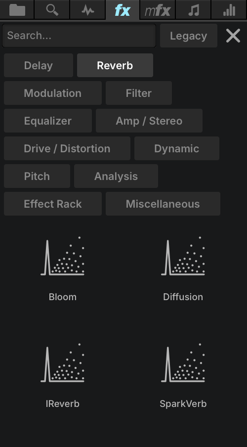
To load a preset, drag it to where it belongs: an oscillator preset onto the Mapping Editor, an effect preset onto a channel strip in the Mixer, a modulation source preset onto any control that can be modulated. A target that can accept the preset highlights as you drag over it.
Module Preset Menu
Every module — oscillator, effect, event processor and modulation source — saves and loads its own presets, so its settings can be reused in other programs. Each ships with factory presets, and you can add your own. The preset controls sit in the module’s upper right:
- The PRESET MENU shows the name of the current preset; press it for a menu of the module’s factory and user presets.
- The PREVIOUS PRESET and NEXT PRESET buttons step through them.
- In the PRESET FILE menu, SAVE PRESET saves a user preset and LOAD PRESET loads one from any location on disk. User presets can be organized into subfolders, as many levels deep as you need. COPY TO CLIPBOARD and PASTE FROM CLIPBOARD transfer the module’s settings, and on sampling oscillators the menu adds the commands described under Saving Samples.
Mixer
The Mixer works like a traditional mixing console, with gain, pan, output assignments, and effects assignment and editing. The top half displays the selected effect; the bottom half, a channel strip for each part, aux and the master.
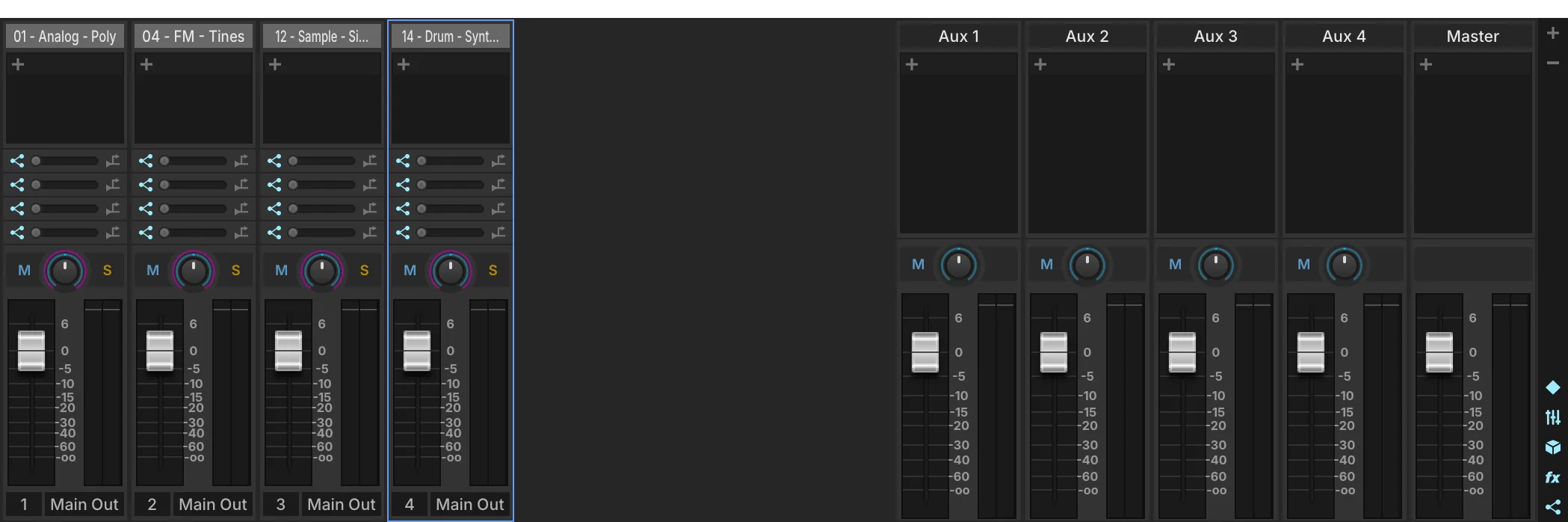
- 1 Add / remove parts
The + and − buttons, at the right of the Mixer, add and remove parts. Drag a part’s name to reorder it.
- 2 Section toggles
Show or hide each section of the Mixer: PARTS, AUXES, MASTER, FX and AUX SENDS.
The part channel strips carry the same settings as the Parts List, laid out as a mixer. Double-click a part’s name to open the Library Browser, or right-click it for Empty Part and Load Program.
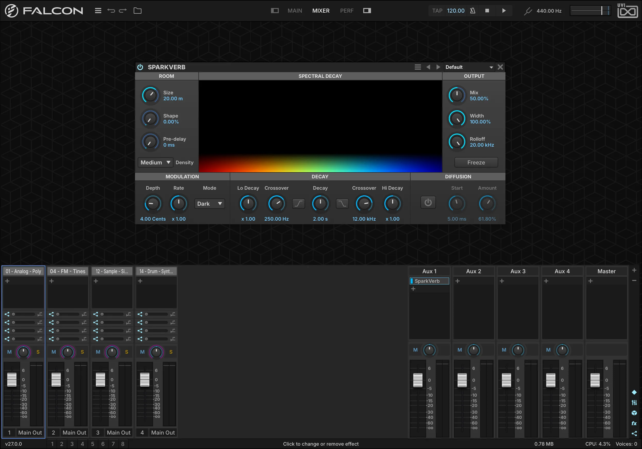
Mixer Effects
- Add an effect with the + button of any channel strip, or by dragging an effect preset from the FX tab of the right sidebar onto that + button. The new effect is selected and its controls appear in the effect editor above — the same module as in the Effects tab.
- Replace an effect by pressing and holding its name and choosing another, or by dragging an effect preset onto it.
- Bypass an effect with the button next to its name, by Shift-clicking its name, or with its POWER button in the effect editor.
- Remove an effect by pressing and holding its name and choosing Empty, or with its X button in the effect editor.
Auxes
The Mixer also shows the master aux buses, four by default (see Aux FX). Each part’s channel strip has a send to each of them, with an enable/bypass switch on the left and a pre/post-fader switch on the right; sends are post-fader by default. With more than four aux buses, scroll the sends to reach the others. The aux channel strips are like the part strips without the part-specific settings, and always output to the Main Out.
Master
The Master channel strip takes effects like the parts and auxes, and its fader is the Global Volume.
Performance
The Performance view gives a bird’s-eye view of all parts at once: an overview when there are many parts, or quick access to part settings during a live performance.

- 1 Part settings
The same controls as in the Parts List. When the Parts column is narrow, some of them are hidden.
- 2 Keyboard / Velocity Range
Restrict the part’s key and velocity range, independently of the program’s layers and keygroups. Drag the ends to adjust, drag the middle to move the range, or hold Alt/Option while dragging to apply a fade.
- 3 Keyswitch
A note that switches the part on when played — to toggle between articulations of one instrument, such as staccato and legato strings. Playing one part’s keyswitch switches the other keyswitched parts off. Tick the checkbox to enable it, then double-click the note name to set the note.
Preferences
Falcon’s general settings are set in the Preferences window: choose Preferences from the Main Menu. The window has four pages: General, Streaming, OSC and Soundware.
General
When set to One Shot, every sample dropped into Falcon is imported in one-shot mode. To change one sample’s mode, see Sample Editor.
Asks whether to save when you load another preset or quit Falcon.
The color each new part gets: Grey gives all parts the same shade of gray; Chromatic gives each new part a random color.
Hands the drawing of the interface to your GPU. On Windows, keep your GPU drivers up to date for best results.
The zoom level of the whole interface, from 75 % to 200 % — useful on HiDPI and 4K displays.
The zoom level of the script interfaces on the Info tab only, from 75 % to 200 %.
Forces the best interpolation mode in Sample oscillators when they load.
Shows the Info tab when you load a Soundware with a script interface.
Shows the splash screen when Falcon starts.
When enabled, the mouse wheel changes the knob or slider under the pointer; when disabled, it scrolls the panel underneath.
Reloads the UI state along with a template.
Leaves out the tags that none of the current results carries.
Lists everything the active filters allow before you type anything.
How long the browsers keep the filters you set: Remember, Forget after 1 hour, Forget after 1 day, Forget after 1 week, Forget on close, or Forget (always).
Shows the MOD, MULTIFX and EVENT tabs of the sidebar browsers as category grids rather than folder trees.
Adds the search field and the category filters to the OSC and FX tabs of the sidebar browsers.
Only in the VST plug-in: the output channel configuration Falcon starts with. Stereo by default; mono and surround formats are also offered.
Streaming
Rather than loading whole samples into memory, Falcon can read (stream) them from disk as they play, which balances the load between your computer’s RAM and its disks: it uses less memory, and lets you play more samples than your RAM could hold. Streaming performance depends directly on the speed of the disk: the faster, the better. The default settings suit most uses. To turn streaming on or off for a program, see Program.
The speed of the disk your Soundware sits on — Very fast - SSD, Fast - 7200 RPM, Medium - 5400 RPM, or Slow - USB1 / Network.
How much memory Falcon keeps for samples on their way from the disk, from 1 to 256 MB.
Restores the default streaming settings.
Applies the hard drive type and cache size you chose.
OSC
Open Sound Control (OSC) is a protocol for communication between computers and other audio devices, designed for networked devices. Any app or device that supports OSC can control Falcon remotely. To find a parameter’s OSC path, right-click it and open the OSC submenu (see Assigning Modulation, MIDI and Automation). For general information on OSC, see opensoundcontrol.org.
Makes Falcon available as an OSC destination on the network.
The name you would like this Falcon instance to have on the network.
The UDP port you would like this Falcon instance to listen on.
Once the server runs, the name actually assigned to this Falcon instance. Read-only.
Once the server runs, the port actually assigned to this Falcon instance. Read-only.
Rewrites the underscores in incoming OSC addresses as spaces. OSC addresses cannot contain spaces, so this lets a strictly compliant client reach Falcon elements whose names contain spaces (send Part_1 for Part 1).
Soundware
Each search path is a folder that Falcon scans for Soundware, with three toggles of its own.
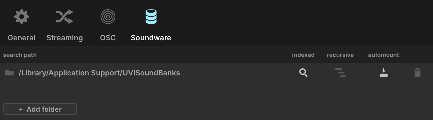
- 1 Search path
A folder Falcon scans for Soundware. You can set several.
- 2 Change folder
Click the folder icon to point this search path to another folder.
- 3 Indexed
The folder is included in the browsers’ search.
- 4 Recursive
The folder is scanned with all its subfolders, not just the folder itself. Meant to be used with Auto-mount. This can significantly increase Falcon’s startup time.
- 5 Auto-mount
Every ISO or UFS Soundware (UVI Soundware comes as
.ufsfiles) found in the folder is mounted at startup. Falcon’s startup time grows with the number of UFS Soundware auto-mounted. - 6 Remove
Removes the search path from the list. The folder itself is not touched.
- 7 Add folder
Adds a search path: browse for the folder you want Falcon to scan.
Oscillators
The building blocks that generate the sound, by sampling or by synthesis.

A straightforward sample-playback oscillator, with a resizable sample display and in-place editing: crop, normalize, silence, reverse, fades, and any Falcon effect rendered into the sample. It suits traditional sample playback, and since samples stream from disk, a program can use tens of thousands of them without a large memory footprint.
Read more ↓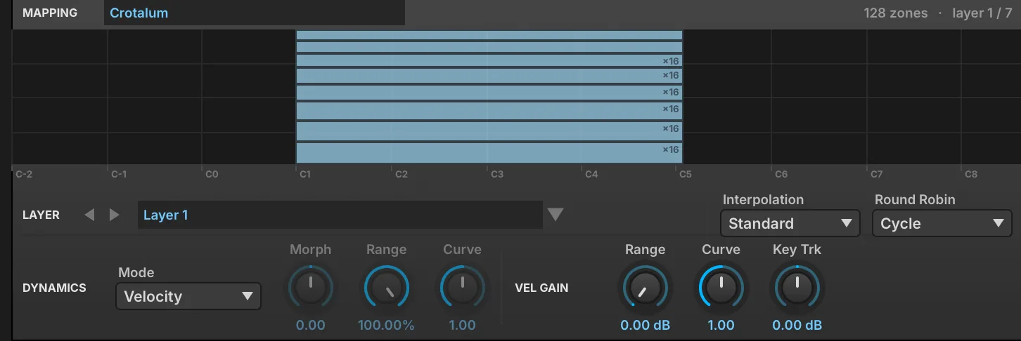
An oscillator that plays a whole set of samples described by a mapping file, in which each zone has its own sample, key and velocity span, round-robin take and layer. It is the oscillator UVI’s own instruments are built on, suited to large multisampled instruments.
Read more ↓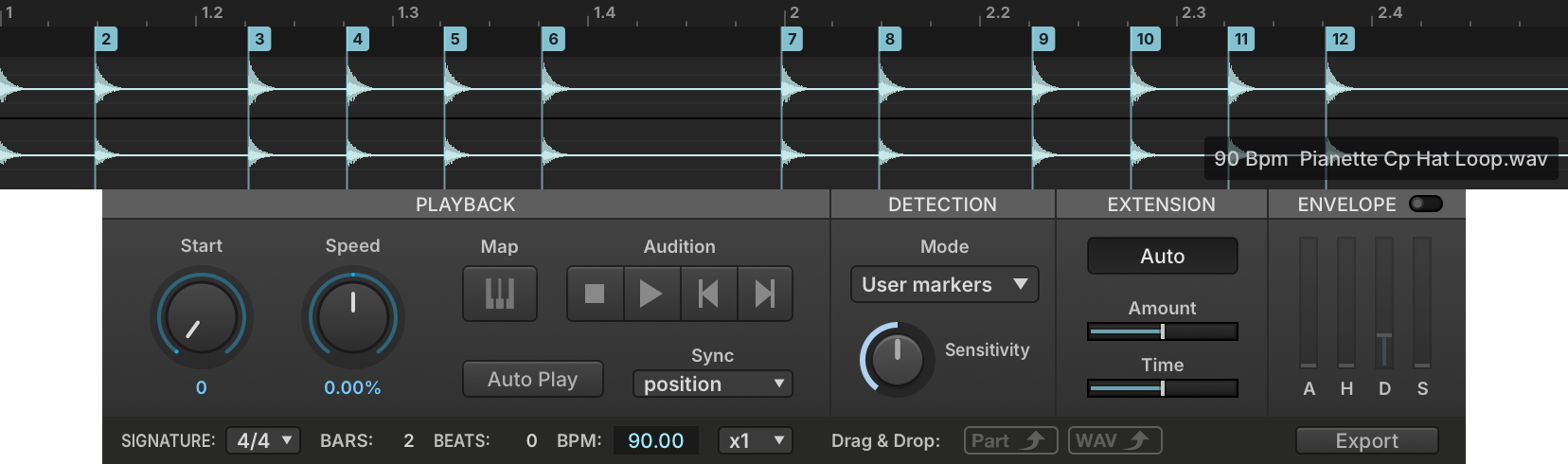
A sampling oscillator that divides a sample into slices at its transients, or at markers embedded in the file such as those of REX files. It suits rhythmic and percussive material: the slices can be resequenced, mapped to keys, or exported by drag and drop as a Falcon patch, separate WAV files or a MIDI sequence.
Read more ↓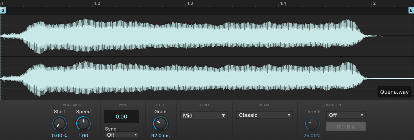
A phase-vocoder sampling oscillator that separates playback speed from pitch, so a sample can be slowed down, held on a single spectrum or synced to the host tempo while its pitch follows the keyboard. Transient detection and stereo phase locking keep rhythmic and stereo material intact at large stretch ratios.
Read more ↓
A low-CPU pitch-shifting sampling oscillator that transposes a sample by up to ±2 octaves in real time while keeping its duration. It suits loops and phrases that must change pitch but not length, with adjustable sample start, playback mode and tempo analysis, and a Solo Mode switch between monophonic and polyphonic algorithms.
Read more ↓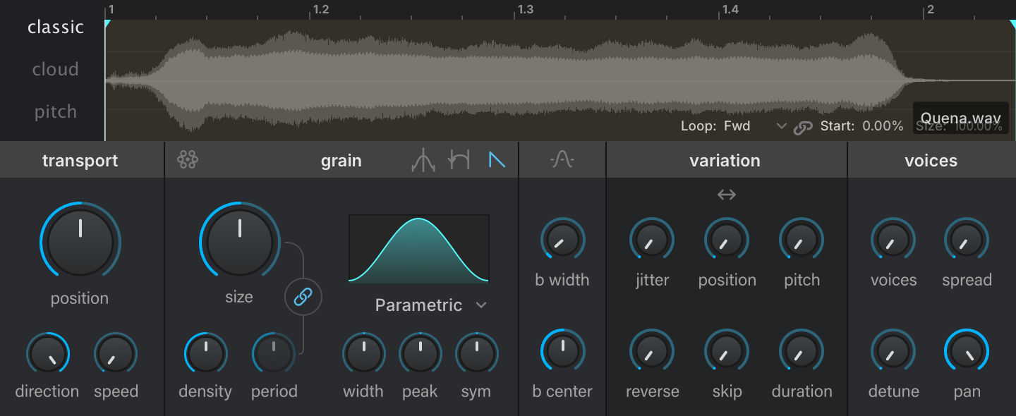
A granular sampling oscillator with Classic, Cloud and Pitch scheduling modes, a parametric grain envelope, and per-grain filtering with formant control. It suits intricate textures and rhythmic motion built from any sample.
Read more ↓
IRCAM’s granular oscillator, which divides a sample into grains and recombines them, with controls such as Size, Density, Jitter, Position, Speed, Direction and Pitch Variation. It suits realistic pitch-shifting as well as soundscapes.
Read more ↓
A multi-voice version of IRCAM Granular, with the same controls plus a section setting the number of voices, their position and their spread. It suits complex unison sounds.
Read more ↓
A sampling oscillator for random-access scrubbing through a sample, with speed and direction control, built on the algorithm of IRCAM Stretch. It gives higher quality than IRCAM Granular in exchange for more processing power.
Read more ↓
A time-stretching and pitch-shifting sampling oscillator built on IRCAM’s phase vocoder, which preserves transients and the spectral envelope. It gives a clear quality improvement over the standard pitch-shifting oscillators, at a higher CPU cost.
Read more ↓
A circuit-modeled recreation of the classic analog drum-machine bass drum, with Tone, Decay and Pulse controls. It covers kicks from soft thumps to hard-hitting punches.
Read more ↓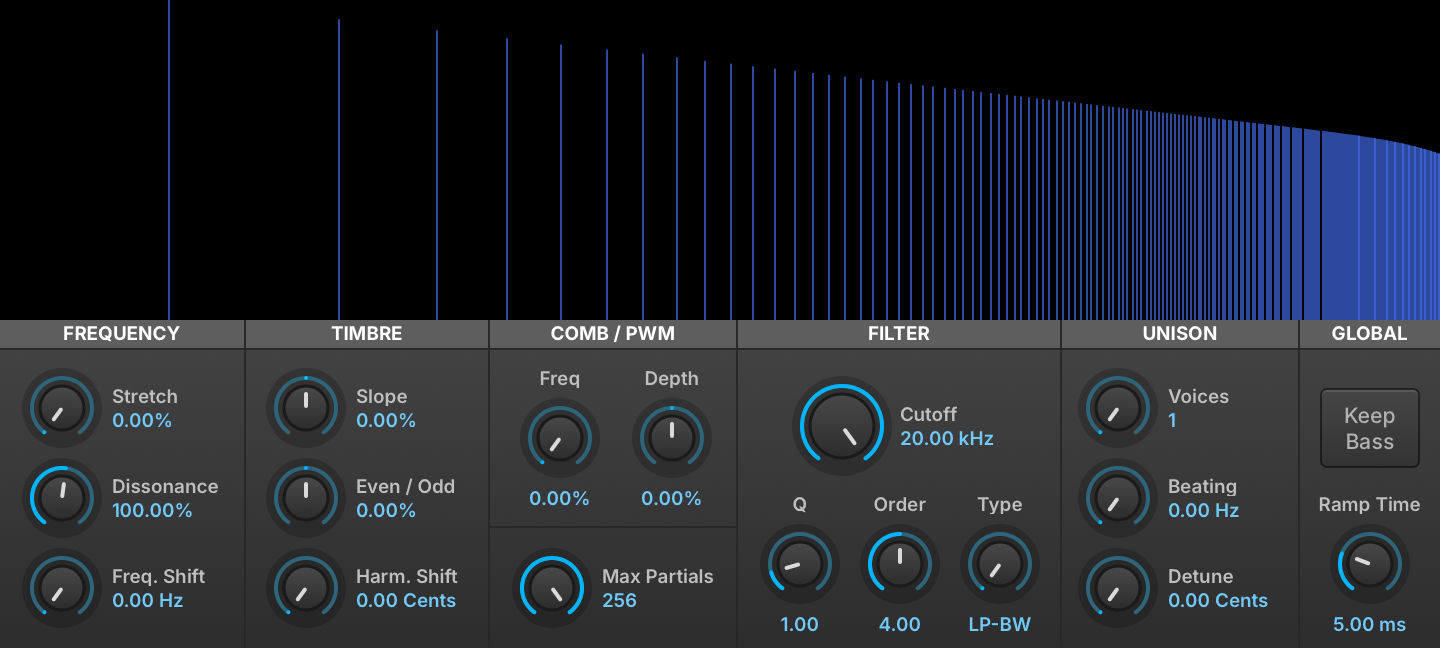
An additive oscillator with controls laid out like a subtractive synth: partial stretching, frequency shifting, fractional-order filtering, even/odd harmonic balance and a continuous morph from square to saw. It gives detailed control over the harmonics through familiar controls.
Read more ↓
A virtual analog oscillator with sine, saw, square, triangle, noise and pulse waveforms, pulse width modulation, sync, and a unison section of up to 8 voices with phase, tuning and spread control. It is the basis for classic subtractive synth sounds.
Read more ↓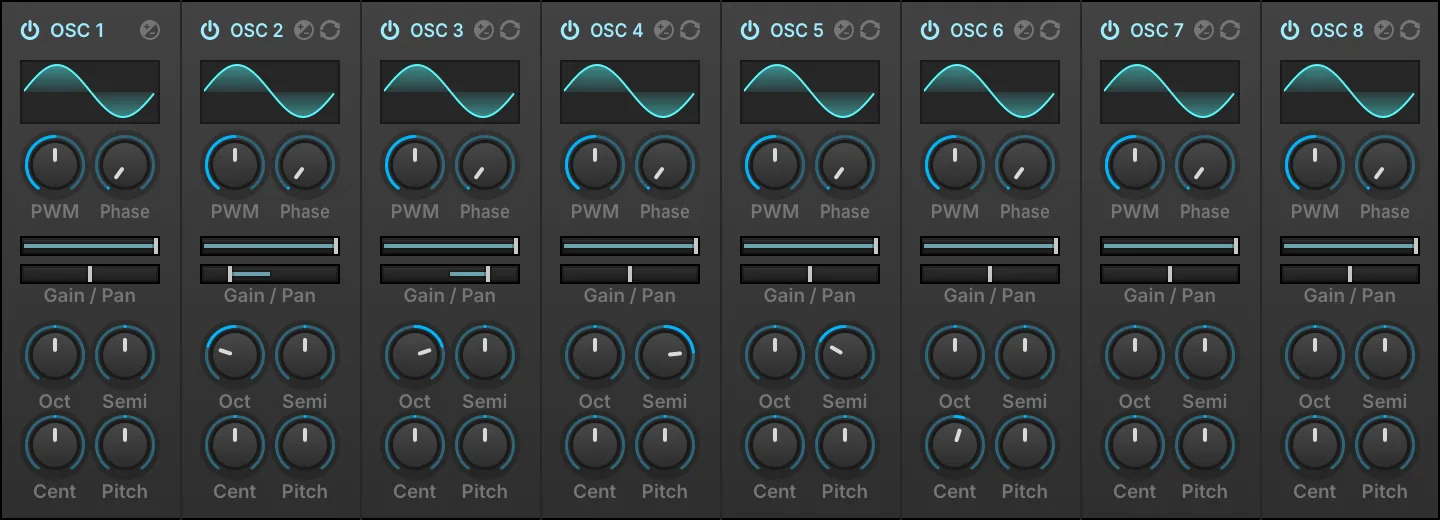
An 8-voice version of the Analog oscillator in which each voice has its own pan, gain and pitch, in place of the Unison and Sync sections. It suits quick layering and detuning of several oscillators in one module.
Read more ↓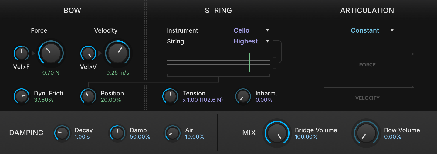
A bow and string emulation with in-depth control over numerous articulation modes. It produces a wide variety of bowed string tones.
Read more ↓
A percussion oscillator that combines a pitched oscillator and a noise generator, each with its own AD amplitude envelope, plus pitch modulation on the oscillator and EQ and distortion in the master section. It suits drum and percussion sounds built from scratch.
Read more ↓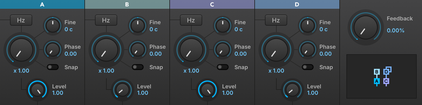
A four-operator FM oscillator with 11 operator configurations, working in ratio or Hz mode, with Snap Ratio (which quantizes modulation frequencies to harmonics) and Start Phase controls. It suits classic FM timbres.
Read more ↓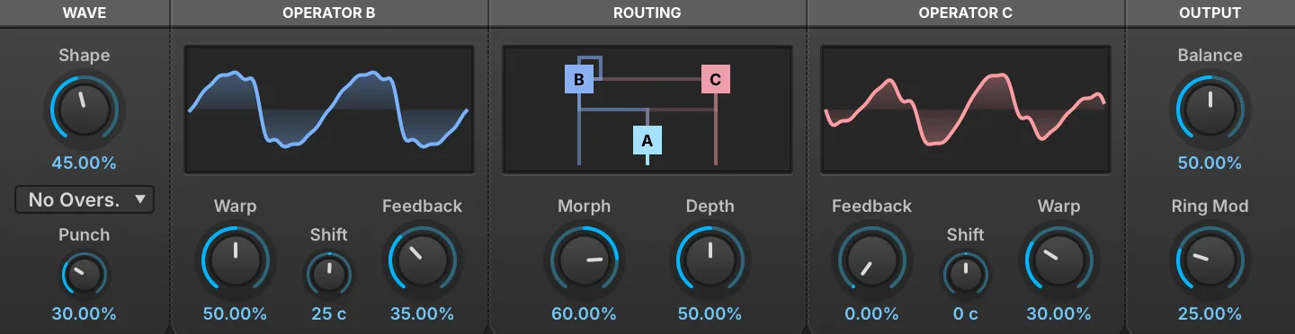
A three-operator FM oscillator whose single Morph control sweeps the routing from one series chain, through both modulators in parallel, to the other series chain. Since Morph can be modulated like any other parameter, it suits sounds whose FM topology itself moves.
Read more ↓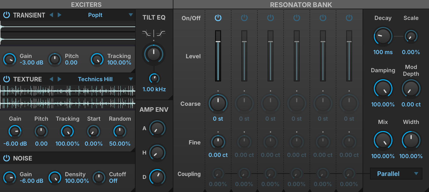
A resonator oscillator in which three mixable exciters (transient, texture and noise) drive a bank of six resonators, each with its own coarse and fine tuning and coupling. It suits resonant, physically inspired tones.
Read more ↓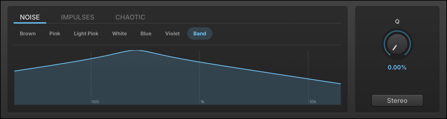
A noise oscillator with 15 noise shapes, from colored noises (white, pink, brown, blue, violet) to chaotic and sparse ones such as Lorenz, Rossler, Crackle, Logistic, Dust and Velvet. It provides noise sources for textures and percussion, with extra controls such as Static Density and Logistic Chaos on the dynamic shapes.
Read more ↓
A drawbar organ oscillator with 9 harmonic bars, each with its own gain and pan, and a percussion section with Fast/Slow and Harmonic controls. Paired with the Rotary effect, it gives a classic organ sound.
Read more ↓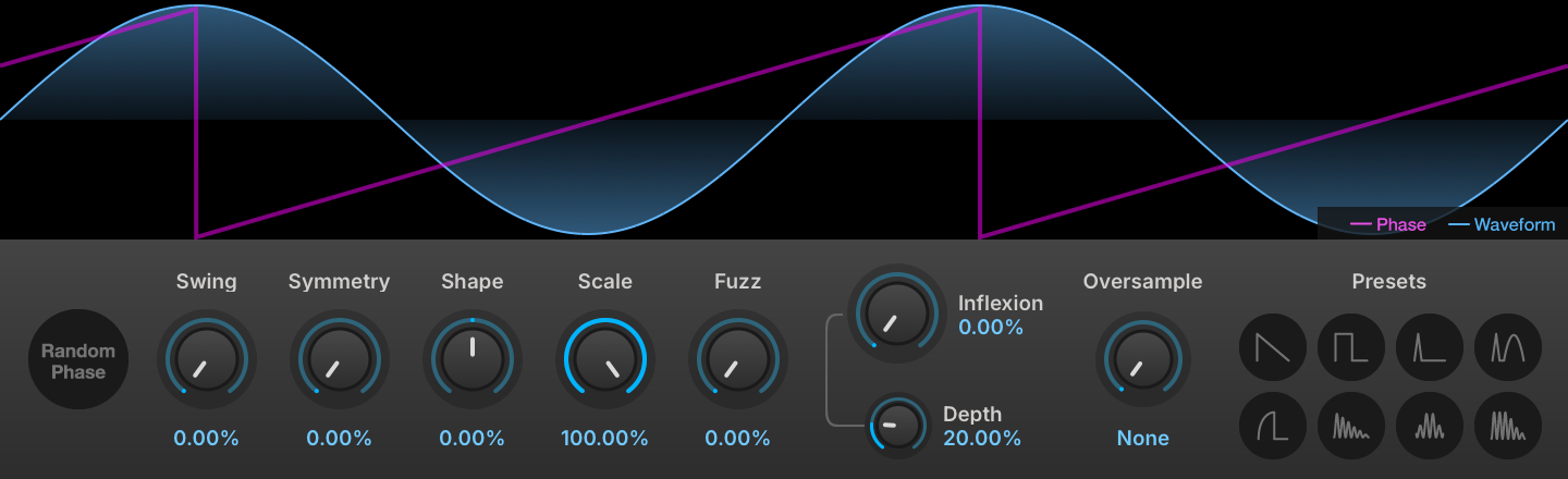
A phase distortion oscillator that shapes waveforms with Symmetry, Inflexion and Fuzz controls. It covers timbres from subtle warmth to aggressive digital tones and complex textures.
Read more ↓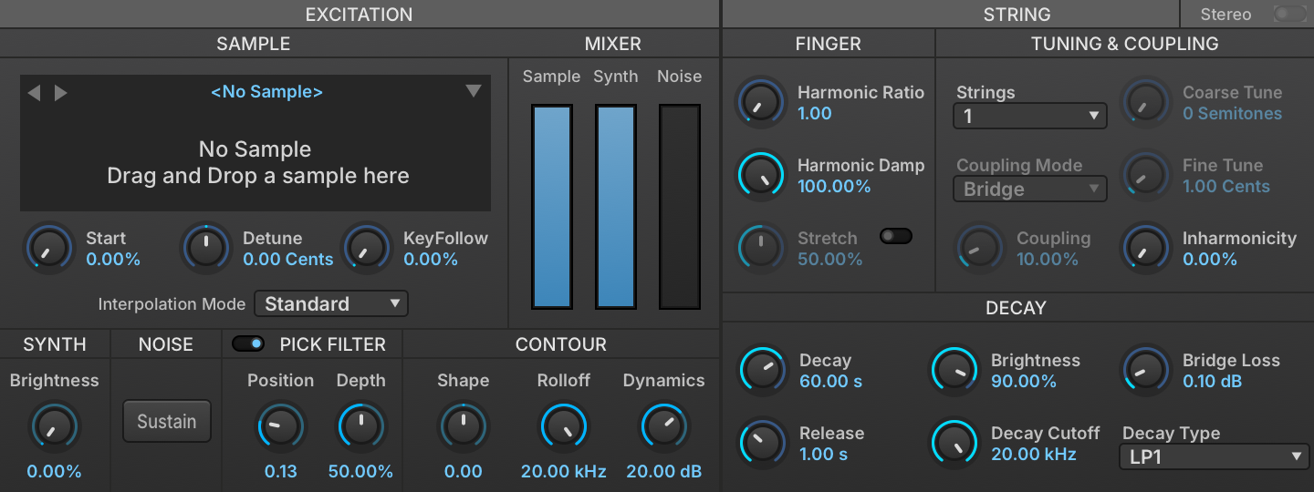
A physically inspired string synthesis oscillator: a short excitation is fed through a filtered delay line, and the excitation waveform, filter style and other settings shape the decay. It suits synthetic plucked sounds with a natural decay.
Read more ↓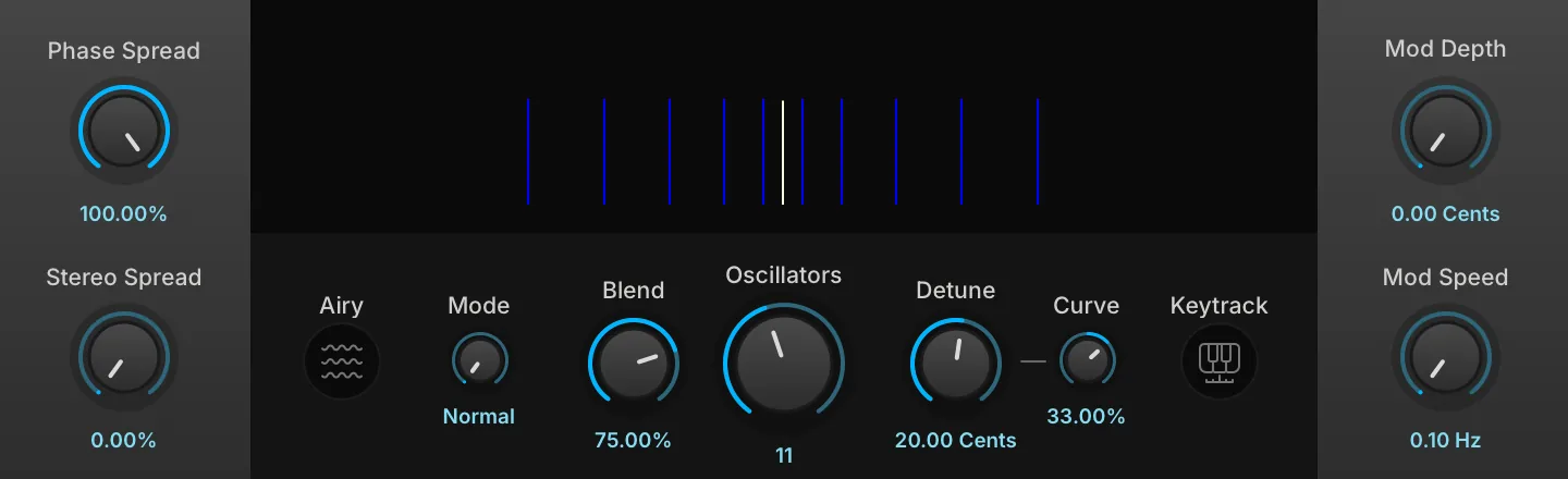
An oscillator that stacks up to 24 sawtooth oscillators, with Detune, Stereo Spread and Blend controls. It suits large pads, leads and dense textures.
Read more ↓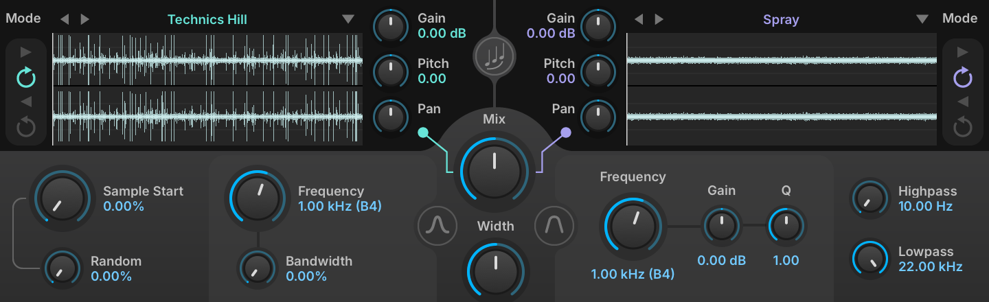
A dual sample-based oscillator with key-tracked band-pass and peak filtering, mix, pitch, playback modes, stereo controls and randomness, and hundreds of built-in samples. It suits complex, varying textures.
Read more ↓
A vocal synthesis oscillator based on the vintage VOSIM technique, with two modes, Formant and Phonem, each with its own controls. It suits vowel-like and formant sounds.
Read more ↓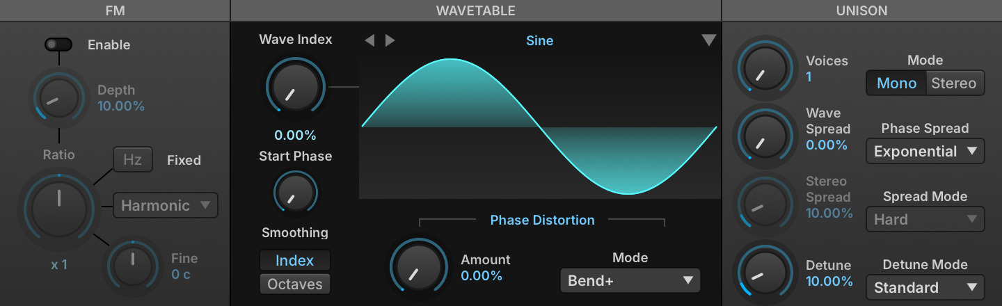
An oscillator that plays one waveform at a time from a table of waveforms, and moves between them as its Wave Index changes. It suits sounds whose timbre changes over time.
Read more ↓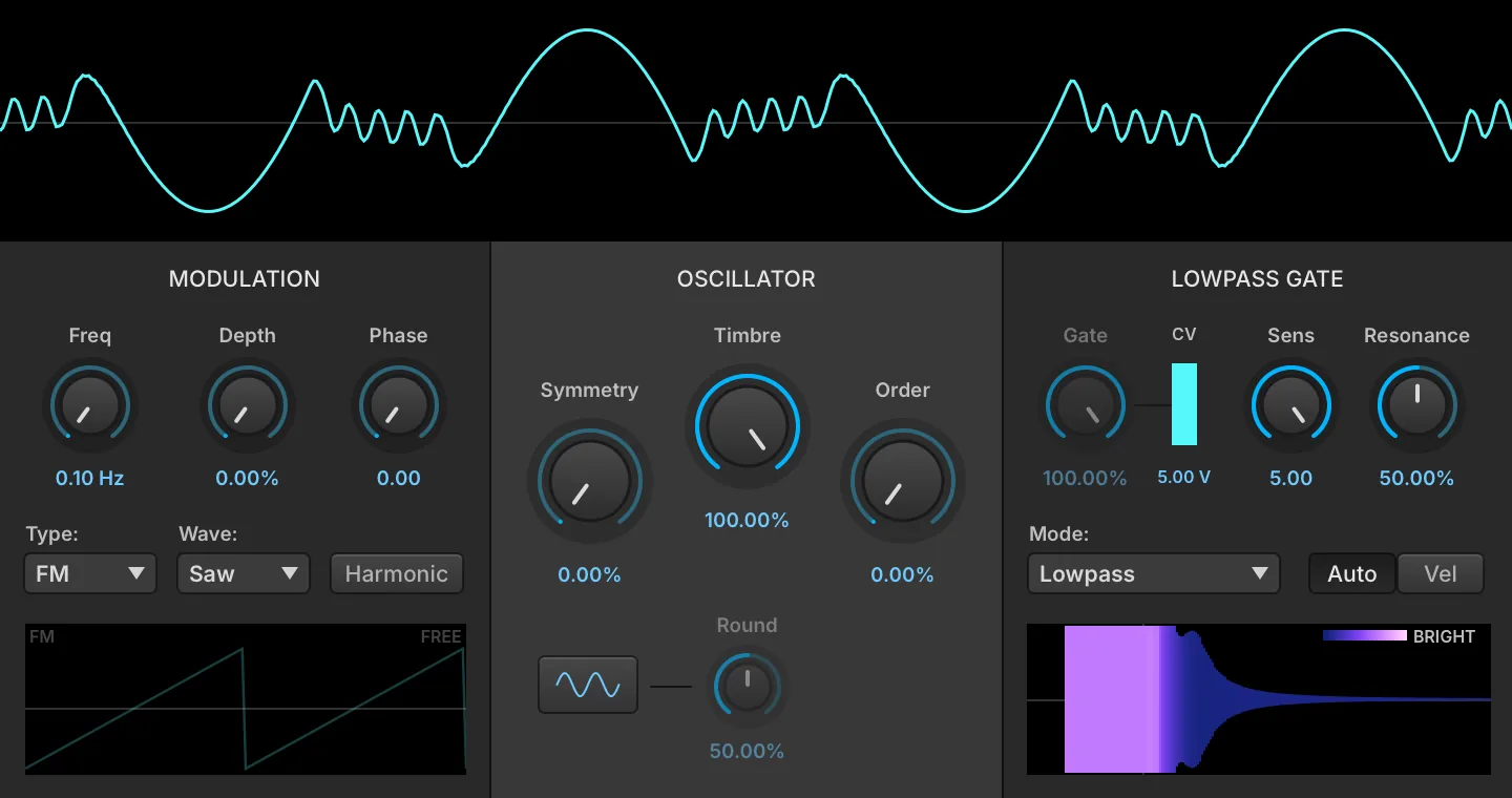
A complex oscillator in which a sine core drives a circuit-modeled wavefolder and then a vactrol low-pass gate, with an internal modulator adding frequency or amplitude modulation ahead of the folder. It suits plucked percussive tones, evolving bells and metallic drones.
Read more ↓Sampling Oscillators
Falcon includes 10 sampling oscillators each equipped with a unique feature set suited for a variety of tasks from basic playback, loop slicing, to advanced time stretching and granular processes.
All of them share a set of controls in the module header. The gears button shows or hides the oscillator’s parameter panel, leaving just the waveform display; the choice is remembered and applies to every sampling oscillator (out of the box the panel starts hidden on Sample and shown on the others). The info button overlays the loaded sample’s details: its path, bit depth, sample rate and channel count, its length in seconds, frames and megabytes, and its start/stop and loop markers or One Shot status. The module menu adds SAVE SAMPLE and SAVE SAMPLE AS…, each with a “with playback options” variant that writes the oscillator’s start, end and loop settings into the file. Dropping an audio file anywhere on the editor loads it into the oscillator.
Sample
A no-frills workhorse sample oscillator, ideal for basic soundboards and traditional sample playback. The Sample display can be interactively resized and provides editing functions such as crop, normalize, silence, reverse and fade in/out along with the ability to apply any of Falcon’s effects in-place. Due to Falcon’s ability to efficiently stream samples from disk you can manage tens of thousands of samples at once without a massive RAM footprint.
SAMPLE START (0–100 %) sets the starting point for playback when the sample is triggered, as a percentage of the time between the Sample Start and Sample End markers in the sample file (see: Interface › Sample Editor).
The INTERPOLATION MODE sets the quality of the transposition. Choosing Lo-fi will reduce the amount of processing needed to transpose the file compared to Standard mode, and likewise choosing Best will increase the processing overhead. (For other styles of transposition, try the other sampling oscillators as well.).
When ALLOW STREAMING is enabled, the sample will be streamed from disk if the program has Streaming enabled. When disabled, the sample will always be played from memory and not streamed from disk, even if Streaming is enabled for the program.
REVERSE sets the sample playback mode to reverse.
MultiSample
MultiSample plays a whole set of samples from one oscillator. A mapping file describes the zones — each one a sample with its own key and velocity span, its round-robin take and its layer — and the oscillator sends every note to the zone that matches it. It is the oscillator UVI’s own instruments are built on. The editor is read-only: a mapping is authored as a file, and Falcon has no way to write one back, so the editor loads a mapping and shows it, and the zones are changed in the file itself.
Click the file name beside MAPPING to choose a mapping, or drop a .dmap, .sfz or .xml file anywhere on the editor. The readout at the right of that row counts the zones of the layer on display, gives its position among the layers (for example layer 3 / 12), and reports how many samples could not be found.
The zone map below plots the zones of the displayed layer, key from left to right and velocity from top to bottom, on the same axes as the Mapping Editor. Round-robin takes that share a span are drawn as one zone, marked with their count (×4); zones still loading are drawn dimmer, and zones whose sample is missing are outlined in red. While you play, the map highlights the column of each held key and marks its velocity, so you can see which zone the note lands on. Hovering a zone shows the sample it holds, its key and velocity span, its round-robin index, its base note, tuning and gain, how many takes share the span, its maximum sample start and its velocity shelf, and whether it is purged, not found or still loading.
LAYER chooses which layer the map shows, one at a time. The arrows step through the layers and wrap around; clicking the layer name opens a menu of all of them. Layer names that use slashes, such as Sustain/Close/Soft, are grouped into submenus on each slash, which keeps a mapping with hundreds of layers navigable. A badge reads PURGED when the whole layer has been dropped from memory, PART PURGED when only some of its zones have. The editor has no per-layer solo or mute: which layer plays is decided by the note, or by the program’s script.
INTERPOLATION sets the quality of the transposition — Lo-fi, Standard or Best — as it does on the Sample oscillator.
ROUND ROBIN chooses which take is played when several zones share the same key and velocity span: First always plays the lowest-numbered take, Cycle advances through them in order, and Random picks one at random.
Dynamics
MODE chooses how the velocity layers are played. Velocity picks a single layer per note, as a conventional keymap does. Continuous and Velocity XFade instead treat the layers as a ladder and crossfade between the two that bracket the current position, so the timbre moves continuously rather than in steps.
MORPH (±100 %) sets the position on that ladder. In Continuous mode it is the position itself; in Velocity XFade it offsets the position the note’s own velocity sets. It is a per-voice control read afresh on every block, so it keeps moving the timbre of a note that is already held — assign it to a controller, to aftertouch or to MPE pressure.
RANGE (0–100 %) restricts how far down the ladder Morph reaches, leaving the softest layers out of play, and CURVE (0.25–4) shapes how quickly it travels. Both are available only when Mode is not Velocity.
Vel Gain
RANGE (0–90 dB) sets how much quieter the softest velocity is than the hardest, and CURVE (0.25–4) shapes that fall, 1 being a straight line in decibels. KEY TRK (±6 dB) adds to the range for every octave above middle C, so the top of the keyboard can be made more or less dynamic than the bottom.
Slice
Ideal for rhythmic and percussive material, the Slice oscillator can divide samples into discrete keygroups to be resequenced. Adjust transient sensitivity manually or use embedded markers like those found in REX files. Sliced files can be exported by drag and drop in several ways, including as a Falcon patch, discrete WAV files or a MIDI sequence.
Tempo
To set the loop’s tempo, choose its SIGNATURE — 2/4, 3/4, 4/4, 5/4, 6/8 or 7/8 — and enter the loop’s duration in BARS (0–99) and BEATS (0–99). The BPM field is read-only and updates as you change the other tempo parameters.
If you’d like to play back the loop at a multiple of its original tempo, use the TEMPO FACTOR menu for coarse speed adjustments, choosing /4, /2, x1, x2 or x4.
Detection
The Detection MODE setting determines whether to use slices already saved in the file (Imported) or the slices you’ve defined (User markers). Loops in UVI Soundware will have imported slices, as will common loop formats such as REX and Apple Loop files.
If you choose to create your own slices, use the SENSITIVITY knob (0–1) to automatically detect and create slices; it is only available with User markers selected. At the far left, slices will be created only by very prominent beats and there will be a small number of slices; at the far right, slices will be created by more subtle variations in the sample and there will be a larger number of slices.
To add a slice manually, double-click in the space between the sample’s waveform and the time ruler. You can also add multiple slices at once on divisions of the musical grid by right-clicking, choosing ADD MARKERS WITH GRID SETTING, and choosing a beat division such as eighth note.
Existing slices can be moved by clicking and dragging anywhere along the slice. To protect a slice from being edited, right-click the slice and choose LOCK. The slice can be ignored by right-clicking it and choosing MUTE, or it can be removed entirely with DELETE.
Playback
A single slice can be auditioned by clicking anywhere on its waveform. When a slice is selected, you can also use the forward/back AUDITION buttons to audition the next/previous slice; the left and right arrow keys are shortcuts for those two buttons. The Audition play and stop buttons can be used to play back the entire file. When AUTO PLAY is enabled, the loop will be triggered when Falcon’s playback begins. (This button is the same as the AutoPlay button in the Parts List.).
SYNC determines how the loop interacts with Falcon’s tempo and playback position. When set to “position,” the sample is played back at Falcon’s tempo and also locks to its playback position; in “tempo” mode, only the tempo is matched. When set to “off,” Falcon’s tempo and playback position are ignored and the sample is played back at its original tempo.
In all Sync modes, the START control sets the slice where playback begins when the loop is triggered, with zero being the first slice in the loop. The SPEED parameter adjusts the loop’s playback tempo, up to 50% faster or slower.
For MAP, see: Exporting and Converting the Loop.
Extension
When the loop’s playback tempo is slower than its original tempo, you can choose to extend the slices so that the loop is still continuous. With the Extension section’s AUTO button enabled, extension of the slices will be configured automatically. When disabled, use the AMOUNT (0–200 %) and TIME (0–100 %) parameters to fine-tune how the slices are extended.
Envelope
You can also optionally enable a slice envelope. When enabled with the ENVELOPE button, the ATTACK (0–100 ms), HOLD (0–2 s), DECAY (0.01–2 s) and SUSTAIN (0–100 %) parameters adjust an amplitude envelope that is applied to each slice as it is triggered.
Exporting and Converting the Loop
The entire loop can be exported as a new audio file with the WAV button. When you press on it and drag, it creates a new audio file that can be dragged to your host application or desktop. The new audio file is created with all of the current settings applied: tempo, envelope, etc.
Or, to export the slices with each as an individual audio file, choose EXPORT and specify the folder where the samples will be saved. To save a program with the slices mapped to individual keys, press on the PART button and drag it to the Parts List or to the desktop or other folder.
If you would prefer to create a new layer in the current program rather than a separate program, press the MAP button in the Playback section. This will Mute and MIDI Mute the original layer, and create a new layer with the slices mapped to individual keys.
This will also change the audio drag & drop button to a MIDI button. When you press on it and drag, it creates a MIDI file that can be dragged to your host application or desktop. The MIDI file triggers the slices in their original order and timing, which you can then edit for new arrangements of the slices.
Spectral Stretch
Spectral Stretch plays a sample through a phase vocoder, which separates the speed of playback from the pitch: the sample can be slowed to a crawl, held on a single spectrum, or run in time with the host, while the pitch of the note still follows the keyboard. Transient detection and stereo phase locking keep rhythmic and stereo material intact at stretch ratios that would otherwise smear it.
The sample editor sits above the controls, which are grouped into sections; when the panel is narrow the sections wrap onto several rows rather than shrink. Start and Speed are the two controls available as modulation destinations, the rest of the panel being set once for the oscillator.
Playback
START (0–100 %) sets the position in the sample where playback begins when a note is triggered.
SPEED (0–4x) sets how fast playback travels through the sample. The pitch is unaffected, so lowering the speed stretches the sound in time rather than transposing it. Below a hundredth of normal speed the voice freezes: the analysis position is held, and the spectrum under it goes on sounding for as long as the note lasts.
Sync
SYNC sets how Speed is read. Off leaves it continuous. Ratio snaps it to eleven musical ratios spanning two octaves either side of unity — 1/4, 1/3, 1/2, 2/3, 3/4, 1, 4/3, 3/2, 2, 3 and 4 — and the Speed knob shows the fraction in place of a number. Tempo applies the same snap and multiplies it by the ratio between the host tempo and the sample’s own tempo, so the sample keeps time with the session.
The sample’s own tempo is set with the TEMPO (0–300) field. A Tempo of 0 means “not set”, in which case the tempo stored in the sample file’s metadata is used instead.
STFT
GRAIN (40–200 ms) sets the length of the analysis window. Short windows follow attacks closely at the cost of low-frequency detail, while long ones resolve steady tones and low registers but blur transients. When the sample is transposed, the window covers a different length of it.
Stereo
The STEREO menu sets how the phase relationship between the left and right channels is handled. Off leaves the two channels independent. Every other entry locks them together and names the channel the others are locked to — Mid, Left, Loudest, or PCA, which follows the dominant direction of the stereo signal — so a stereo image survives the stretch instead of drifting apart.
Phase
The PHASE menu chooses how the phase of each analysis frame is carried over to the next, which is what decides how coherent the stretched sound stays:
-
CLASSIC: each frequency band is advanced on its own, as in the original phase vocoder.
-
LOOSE: neighboring bands are summed together, so a partial and the bands around it stay in step.
-
LOCKED: the peaks are located and the region around each one is rotated as a block.
-
LOCKED SOFT: the same peak locking, with the deviations around each peak scaled rather than discarded.
-
COHERENT: the phase is reconstructed across time and frequency at once, holding transients and tonal material together; this is the default.
-
COHERENT DIFFUSE: the same, with random phase below the noise floor for a more diffuse, textural result.
-
COHERENT FULL: the same with no threshold at all, every band passing through the reconstruction.
Transient
The TRANSIENT menu sets what happens when an attack is detected: Off ignores them and stretches straight through, Reset restarts the phase so the attack comes out sharp, and Hold freezes the phase across it.
THRESH (0–100 %) sets how much spectral movement counts as an attack, low values catching a great deal and high values only the sharpest. PER BIN applies the handling to the frequency bands where an attack was found rather than across the whole spectrum. Both are inactive while the Transient menu is set to Off.
Stretch
A real-time, low-CPU pitch-shifting sample oscillator. Stretch can adjust pitch up to ±2 octaves while maintaining sample duration. Freely adjust sample start time, playback mode and tempo analysis. Use the Solo Mode button to switch between discrete monophonic and polyphonic pitch-shifting algorithms.
The Stretch oscillator will pitch-shift the sample ±2 octaves from its root key. Beyond that range the pitch will be constant, even if the keygroup’s key range extends further.
SAMPLE START (0–100 %) sets the starting point for playback when the sample is triggered, as a percentage of the time between the Sample Start and Sample End markers in the sample file (see: Interface › Sample Editor).
Additionally, when LEGATO MODE is enabled, if a new note re-triggers the sample, playback will continue from the current sample position but at the new pitch. With Legato mode disabled, playback will always begin from the sample’s start position.
Sample Tempo
Although the speed of sample playback is constant across its key range, enabling SYNC will sync the sample’s playback speed to Falcon’s tempo. Set the sample’s base tempo with the TEMPO (0–300) field, which can be modified with the TEMPO FACTOR (x0.25–x4, continuously variable) and TEMPO FINE (±50 %) controls. A Tempo of 0 means “not set”: when a sample is loaded, Falcon substitutes the tempo found by its own analysis, or failing that the tempo stored in the sample file’s metadata, and writes the resolved value into the field.
Analysis
To fine-tune the pitch-shifting, adjust the GRAIN SIZE (10–100 ms) and SENSITIVITY (0.1–10) parameters. For highly rhythmic or percussive material, try increasing Sensitivity for better transient preservation. Additionally, if a sample contains a solo instrument, try enabling SOLO MODE for the best pitch-shifting; for polyphonic samples, turn off Solo Mode.
Grains
Falcon’s most advanced granular engine, rebuilt for deep sound design. Explore Classic, Cloud, and Pitch scheduling modes, a fully parametric grain envelope, and per-grain filtering with formant control for intricate textures and rhythmic motion.
Grain Scheduling Mode
-
CLASSIC: periodically spaced grains
-
CLOUD: randomly spaced grains
-
PITCH: pitch-periodic grains
Waveform Display
LINK enables Loop Start link to Transport Position. Click the left blue line or drag the START (0–100 %) to set the loop start point. Click the right blue line or drag the SIZE (0–100 %) value to set the loop end point.
LOOP, at the left of the same bar, sets what the play head does when it reaches the end of the loop: None ignores the loop and reads on to the end of the play zone, Fwd returns to the loop start, and Fwd-Bwd turns round and reads back the other way. The loop is the region set by START and SIZE (or by POSITION when LINK is on), whether or not the sample carries a loop of its own.
Transport
POSITION (0–100 %) determines the starting point for grain playback within the audio sample. This is the central point around which grains are generated. SPEED (0–10) sets the speed at which the main Position marker moves through the sample, with 0 as static and higher values faster.
DIRECTION (−1 to 1) sets the direction of playback, from +1 for fully forward to −1 for fully reverse.
Grain
RANDOM PAN (the left icon of the title bar): enables randomization of the pan position for each grain. The voices are panned in a more structured, alternating pattern when disabled.
ATTACK (the right icon of the title bar): enables triggering of the very first grain instantly when a note is played, rather than waiting for the first period to elapse. This provides a more immediate attack.
CENTER GRAINS (the icon left of Wrap Grains): Position names the middle of each grain instead of its start, so every grain is pulled back by half its own length. Because the offset follows the grain size, grains stay centered on Position as the size is modulated.
WRAP GRAINS AT LOOP (the icon between Center Grains and Attack): a grain that runs into the end of the loop wraps back to the loop start instead of reading on into the material past it. Where Loop Mode moves the play head, this moves each grain; it does nothing when Loop Mode is None, and is grayed out there.
SIZE (0.002–2 s) (in Classic and Cloud mode) sets the duration of each individual grain in seconds. Shorter grains sound more textural and abstract, while longer grains are more recognizable as snippets of the original sample. FORMANT (−12–12 st) (in Pitch mode) shifts the resonant character (timbre) of the sound without changing its fundamental pitch. This can make a sound source sound like it’s coming from a larger or smaller body.
PERIOD (0.001–2 s) sets the base time interval between the start of successive grains.
Size and Period are both tempo-syncable: with the module’s sync button engaged they read in bars and beats rather than in seconds, and follow the host.
PITCH CORRECTION chooses how transposition is compensated — None, Grain size or Period.
The LINK button beside PERIOD (not the Link button on the waveform bar) sets the period to half of SIZE and grays out the Period knob.
DENSITY (0.1–10) sets how many grains overlap. In Classic and Cloud mode it divides the PERIOD, so 2 doubles the grain rate; in Pitch mode it multiplies the grain length relative to the pitch period. The output level is compensated as Density rises.
WIDTH (±100 %) modifies the steepness of the envelope’s attack and decay. Negative values result in a wider, softer envelope, while positive values create a narrower, more percussive sound.
ENVELOPE MODE, under the envelope display, chooses the window each grain is shaped by. Parametric is the continuously variable shape the three controls below draw. Triangle, Hanning, Welch and Squared are exact windows that those same three controls still reshape; Triangle and Welch cannot be reached by the parametric shape, whose curve is always flat at the edges.
PEAKINESS (±100 %) controls the curvature of the envelope. Higher values create a sharper, more defined peak, while lower values result in a smoother, more rounded shape. SYMMETRY (±100 %) adjusts the shape of each grain’s volume envelope. Negative values create a fast attack and slow decay (like a plucked string), while positive values create a slow attack and fast decay (reversed sound). These three controls can also be adjusted by click-dragging the ENVELOPE DISPLAY above.
Band Limit Grains
Click the icon button to enable a dedicated band-pass filter that is applied to each individual grain. BAND WIDTH (1–100 %) controls the width of the per-grain filter. Lower values create a narrow, resonant peak, while higher values allow a wider range of frequencies to pass through.
BAND CENTER (0–100 %) sets the center frequency of the per-grain filter. This allows you to isolate specific tonal characteristics from the source sample for each grain.
Variation
JITTER (0–100 %) introduces a small amount of random variation to the timing of each grain’s trigger, making the sound less robotic and more organic.
POSITION (0–1 s) adds a random offset to the start position of each individual grain. Higher values will grab grains from a wider area around the main Position, creating a more varied texture.
BIPOLAR (the icon above that knob) lets the random offset run both ways. Off, the variation only ever pushes a grain later, so the average read point sits half the variation past Position; on, grains scatter to either side and the average stays on Position.
PITCH (0–12 st) introduces random pitch deviation to each individual grain, measured in semitones. Useful for creating dissonant clouds or subtle chorusing effects. REVERSE sets the probability (from 0 % to 100 %) that an individual grain will play in reverse, independent of the main playback Direction.
SKIP (0–100 %) sets the probability that a scheduled grain will be skipped entirely. This can be used to thin out the texture in a random way.
DURATION (0–100 %) adds randomness to the length of each grain. At 0%, all grains have the exact same duration. Higher values create more variety.
Voices
VOICES (1–8) sets the number of simultaneous grain streams (or playheads). Increasing this number creates a rich, layered unison or chorus effect.
SPREAD (0–10 s) spreads the playback position of the unison voices around the main position.
TIME SPREAD (0–100 %) staggers the grain onsets of the unison voices across the grain period. It has no knob on the panel and is reached from the parameter list.
DETUNE (0–50 cents) applies a small amount of pitch difference between the unison voices, thickening the sound. PAN controls the stereo width of the grains. At 0%, the sound is mono. At 100%, grains and unison voices are spread across the entire stereo field for a wide, immersive effect.
IRCAM Granular
IRCAM’s premier granular oscillator divides an audio sample into grains and recombines them for realistic pitch-shifting or soundscape generation. Adjust Grain parameters such as Size, Density, Jitter, Position, Speed, Direction, Loop Mode, Pitch Variation and Correction Method.
The GRAIN section configures the shape of the grains.
SIZE (5–500 ms) sets the duration of the grains. DENSITY (0.1–10) determines how many grains will be played at once, with 1.00 representing standard playback. With values less than 1.00, there will be silence between the grains with a rhythmic result similar to tremolo; with values over 1.00, there is increasingly more overlap of grains with a harmonic result similar to a chorus or sometimes a ring modulator. JITTER (0–100 %) varies the consistency of grain playback timing.
FADE (0–100 %) sets the amount of the grain affected by the fades of the grain envelope’s attack and decay, as a percentage of the full grain size. At the default 100%, the full grain can be faded, which results in a triangle-shaped envelope. At less than 100%, there is a plateau in the middle, resulting in a more trapezoidal envelope.
SYMMETRY changes the skew of the grain window by balancing the grain envelope attack and decay, as percentages of the grain size:
-
0%: set an attack of 0% and decay of 100%; this results in more percussive grains.
-
50%: set an attack of 50% and decay of 50%; this is the standard, balanced window.
-
100%: set an attack of 100% and decay of 0%; this results in reversed grains.
WINDOW sets the shape of the window (an envelope applied to the signal when creating grains); choose from Triangle, Hanning or Welch curves, or Squared.
PITCH VARIATION (0–1200 cents) adds randomization to the pitch of each grain, from minor variations of a few cents to an entire octave.
PITCH CORRECTION sets how grains are transposed. Transposition is done by resampling, which on its own shortens each grain as the pitch rises; this control chooses what is adjusted to compensate. GRAIN SIZE scales the read window with the transposition, so the grain length you hear and the grain rate both stay as set, and each grain simply covers more (or less) of the source. PERIOD leaves the read window as set, so the grain length you hear scales with the transposition, and the period between grains is scaled by the same amount to preserve the overlap. Transposition is clipped to ±48 semitones.
Position
The POSITION section controls determine the playback position in the sample file.
POSITION (0–100 %) determines the starting point for playback, as a percentage of the duration between the sample start and end markers. With Speed set at or near zero, this can be used to manually scrub to any location within the file. POSITION VARIATION adds randomization to the current position, with a range of zero to 500 ms from the current position.
SPEED sets the scrubbing speed factor, with 1.00 as normal speed, zero as staying in place on the current grain, and 10.00 as 10x faster. DIRECTION sets the direction of scrubbing, from +1.0 for fully forward to −1.0 for fully reverse.
If there is a loop in the audio file, the Loop Mode sets how it will be handled:
-
NONE: The loop will be ignored.
-
FORWARD: The looped section is played forward; when playback reaches the end of the loop, playback begins again from the loop start point.
-
FORWARD-BACKWARD: The looped section is played alternately forward (from the loop start to loop end) and reverse (from loop end to loop start).
IRCAM Multi Granular
A multi-voice implementation of the IRCAM Granular oscillator which can be used to great effect to achieve a range of complex unison sounds. Includes the same control set as IRCAM Granular with an additional section to control voice quantity, position and spread.
This module adds a VOICES section and two Grain settings (DURATION VARIATION and REVERSE, described below) not found in IRCAM Granular.
The VOICES section sets the voice-specific settings. VOICES (1–8) sets the number of unison voices. With a single voice, the result will be similar to the standard IRCAM Granular oscillator.
The other Voice controls set relative variations for each voice; TIME SPREAD (0–100 %) adjusts the timing of each voice’s trigger, and POSITION SPREAD (0–10,000 ms) adds a random variation to each voice’s starting position within the sample file. DETUNE (0–50 cents) spreads the unison voices in pitch symmetrically around the played note.
Grain
The GRAIN section shapes the grains themselves. Most of the GRAIN parameters are the same for the IRCAM Multi Granular oscillator as the IRCAM Granular oscillator; for details, see: Oscillators › IRCAM Granular.
-
SIZE (5–500 ms)
-
DENSITY (0.1–10)
-
JITTER (0–100 %)
-
WINDOW
-
FADE (0–100 %)
-
SYMMETRY (0–100 %)
-
PITCH VARIATION (0–1200 cents)
-
PITCH CORRECTION
DURATION VARIATION (0–100 %) sets the amount of grain size variation. Enabling Reverse will reverse the individual grains (not the overall playback direction, which is controlled with Direction).
Position
The POSITION parameters are the same for the IRCAM Multi Granular oscillator as the IRCAM Granular oscillator; for details, see: Oscillators › IRCAM Granular.
-
POSITION (0–100 %)
-
RANDOM (0–500 ms) — the same Position Variation control as IRCAM Granular, labeled Random here.
-
SPEED (0–10)
-
DIRECTION (−1 to 1)
-
LOOP MODE
IRCAM Scrub
Similar in use to IRCAM Granular, IRCAM Scrub offers random-access scrubbing, speed and directional control but uses the same top-quality algorithm found in IRCAM Stretch. As with IRCAM Stretch, this requires more processing power than the standard granular oscillator.
Playback
The Playback parameters are the same for the IRCAM Scrub oscillator as the IRCAM Granular oscillator; for details, see: Oscillators › IRCAM Granular › Position.
-
SPEED (0–10, default 1.00)
-
POSITION (0–100 %, default 0) — unlike IRCAM Granular, where Position sets a grain center subject to the position variation controls, Scrub’s Position is an absolute read-head location, re-evaluated whenever you change it.
-
DIRECTION (−1 to 1, default 1 for forward playback).
Analysis
The Analysis parameters are the same for the IRCAM Scrub oscillator as the IRCAM Stretch oscillator; for details, see: Oscillators › IRCAM Stretch › Analysis.
-
WINDOW (40–200 ms)
-
PADDING (x1, x2, x4)
-
OVERLAP (3–8)
Remix
Remix mode separates the signal into 3 discrete components and allows you to mix and automate their levels. Enable it with the power switch in the Remix header, then set the level of each component — SINE (harmonics), NOISE and TRANSIENT — from −inf to +12 dB, 0 dB being unity. With Remix disabled the three sliders have no effect, and the Transient level additionally requires the TRANSIENTS option to be enabled.
Options
The Options parameters are the same for the IRCAM Scrub oscillator as the IRCAM Stretch oscillator, except that Scrub has no Legato option; for details, see: Oscillators › IRCAM Stretch › Options.
-
TRANSIENTS (enabled by default)
-
ENVELOPE
-
STEREO
-
SHAPE
IRCAM Stretch
Similar to the Stretch oscillator, but implementing IRCAM’s high-quality phase vocoder for time-stretching and pitch-shifting with transient and envelope preservation. Requires more processing power than the standard pitch-shifting algorithms used in other oscillators but with a significant quality improvement.
Playback
SPEED (0–10, default 1.00) sets the playback rate factor, with 1.00 as normal speed and 10.00 as 10x faster. Very low settings approach a freeze but never quite reach one — the stretch ratio is clamped at 1000x, or 0.001x real time. START (0–100 %) sets the starting point for playback when the sample is triggered, as a percentage of the time between the Sample Start and Sample End markers.
Sample Tempo
Set the sample’s base tempo with the TEMPO field (0–300), then scale it with TEMPO FACTOR (x0.25–x4, continuously variable) and TEMPO FINE (±50 %). SYNC chooses whether playback follows Falcon’s tempo (“ TEMPO ”) or ignores it (“ OFF ”).
Tempo defaults to 0, meaning the sample’s tempo is unknown. In that state Sync has no effect and Speed, Tempo Factor and Tempo Fine act directly as a playback-rate multiplier; once you enter a tempo, playback is scaled by the ratio between it and the target tempo.
Analysis
WINDOW (40–200 ms, default 92 ms) sets the length of the analysis window; the FFT itself is the next power of two above it. PADDING (x1, x2, x4; default x1) sets the amount of frequency oversampling, enlarging the FFT beyond the window. As oversampling is processor intensive, it’s recommended to apply as little as is necessary to reduce unwanted artifacts — often, none will be needed. OVERLAP (3–8, default 4) sets how far the analysis windows overlap: the analysis hop is the Window divided by the Overlap, so higher values give smoother results at the cost of proportionally more processing. 8 is the highest quality, 4 is usually indistinguishable from it, and 3 may introduce small artifacts.
Remix
Remix mode separates the signal into 3 discrete components and allows you to mix and automate their levels. Enable it with the power switch in the Remix header, then set the level of each component — SINE (harmonics), NOISE and TRANSIENT — from −inf to +12 dB, 0 dB being unity. With Remix disabled the three sliders have no effect, and the Transient level additionally requires the TRANSIENTS option to be enabled.
Options
-
TRANSIENTS: Transient preservation; helpful for highly rhythmic or percussive samples.
-
ENVELOPE: Envelope preservation; helpful for avoiding unwanted pitch artifacts with some samples.
-
STEREO: Phase locks between stereo channels.
-
SHAPE: Shape preservation; helpful for preserving the character of voices and other monophonic sounds.
-
LEGATO: New voice playback position will start where currently playing voices are located.
The module menu adds one entry specific to this oscillator, EXPORT WITH STRETCH/PITCH APPLIED, which renders the sample through the phase vocoder at its current settings and writes the result to a WAV file.
Synthesis Oscillators
Falcon includes 18 synthesis-oriented oscillators including featured Additive, VA, analog stack, percussion, noise, organ, FM, Texture, wavetable, west-coast folding and a physical string modeling oscillator.
8o8 Bass Drum
Recreate the legendary analog bass drum with Falcon’s circuit-modeled 808 oscillator. From soft thumps to hard-hitting punches, precise Tone, Decay, and Pulse controls deliver iconic kick sounds perfect for any rhythmic foundation.
Set the playback mode with: KICK for machine emulation with short variable decay and true trigger, or BASS for longer fixed decay and reinit before trigger.
Select the TRANSIENT setting: Soft, Normal or Punchy.
TONE (0–100 %) adjusts the high end of the sound. DECAY (0–100 %) adjusts decay.
TRUE TRIGGER enables true trigger in Kick mode.
Decay and True Trigger are only available in Kick mode; Bass mode uses its own fixed decay and both controls are grayed out.
Additive
An easy-to-use additive oscillator inspired by classic subtractive synthesis, with additive twists like partial stretching, frequency shifting, fractional order filtering, even/odd harmonic control, continuous morph from square to saw and more…
MAX PARTIALS (1–256) sets the maximum number of harmonics. For example an A2 note has 200 harmonics for a sampling frequency of 44.1 kHz. It can be used either for sound design to limit the spectrum or to control the amount of CPU which is proportional to the number of partials.
Frequency
STRETCH (0–100 %) sets the amount of inharmonicity (partial stretching) of the partials. This is similar to the one present in stiff-stringed instruments like the piano or the guitar, great to spice up static spectrums thanks to the dispersive behavior.
DISSONANCE (0–800 %, 100 % being the untouched harmonic series) disturbs the harmonic series according to the law.
fn = f * (1 + n * dissonance).
-
At 100% the partials are harmonics: f * (1 2 3…).
- At 200% we only have odd harmonics: f * (1 3 5 7)
-
At 50% the partials are harmonic but interlaced with the odd partials of its (missing) sub-octave: f * (1 3/2 2 5/2 3) = f * (1 2 3…) + f/2 * (3 5 7…).
-
For irrational amounts, the partials are inharmonic.
QUANTIZE DISSONANCE snaps the Dissonance value to the nearest multiple of 25 % or of 16.67 %, whichever falls closer, so that the partials keep to simple ratios instead of landing on an inharmonic spacing.
FREQ. SHIFT (0–20,000 Hz) transposes the spectrum by a fixed amount in Hertz, making all the partials inharmonic.
Timbre
SLOPE (±100 %) sets the Slope / Tilt of the Spectrum.
-
The default position decays as 1/f and generates a sawtooth wave.
-
At +100% the spectrum is flat, generating a bipolar impulse-like train.
-
At -100% generates a parabolic wave decaying as 1/f^2 (or, when even harmonics are omitted, a wave with the same spectrum as a triangle, see the Even/Odd parameter).
-
EVEN/ODD (±100 %) controls the levels of even and odd harmonics.
-
At +100% removes even harmonics and generates a square wave by default
-
At -100% removes odd harmonics and results in the same waveform at the octave e.g. (2f 4f 6f …) = 2(f 2f 3f …)
-
-
HARM. SHIFT simulates transposition of the spectrum up to +48 semitones, but forces the resulting partials to stay in harmonic relation with the fundamental frequency. This can be compared to (soft-)hard-sync of analog oscillators. Below one semitone the value is displayed in cents, and in semitones from one semitone upward.
Comb/PWM
FREQUENCY (0–100 %) sets the relative frequency of a comb filter applied to the harmonic series of the oscillator.
This is useful to simulate PWM (Pulse Width Modulation) by sweeping the frequency of notches in the spectrum. DEPTH (±100 %) sets the amount of cancellation of the Comb Filter; it is bipolar, so positive and negative amounts cancel complementary sets of partials.
Filter
CUTOFF (20–20,000 Hz) sets the cutoff frequency of the fractional order filter. Q (0.5–100) sets the resonance of the filter (available according to Filter Type). ORDER adjusts the order / slope of the filter. This includes fractional filter slopes from 0.0 to order 8.0 (48 dB/octave) that cannot be achieved with traditional filters. TYPE sets the type of filter: LP-BW, BP-BW and HP-BW are Butterworth low-pass, band-pass and high-pass (no Q), while LP-Res, BP-Res and HP-Res are their resonant counterparts.
Unison
VOICES (1–3) sets the number of unison voices.
BEATING (0–10 Hz), when Unison is activated, sets the fixed amount in Hertz that partials are shifted.
This results in natural built-in Amplitude Modulation (with no LFO involved) whose frequency can be controlled by the Beating frequency. (Only possible with additive synthesis.) DETUNE (0–40 cents) sets the detuning in cents of each unison voice. PHASE SPREAD (0–100 %) offsets the start phases of the unison voices either side of the common start phase, spanning a quarter of a cycle at the default 100 %; with a single voice it has no effect.
Global
KEEP BASS forces the fundamental frequency of the oscillator to be preserved. Some spectral modifications like Comb or HarmShift may result in cancellation of the fundamental frequency, which is not always desired; KEEP BASS retains the fundamental frequency as a reference point while the remaining parts of the spectrum are being processed.
RAMP TIME (0–1000 ms) sets the Ramping time between amplitude changes.
START PHASE (0–100 %) sets the phase at which the partials start when a note is triggered. The whole series is shifted by the same amount rather than delayed, so moving it changes the shape of the waveform: at the default 0 % every partial starts as a sine, and a quarter of the way round they line up into a sharper, more impulsive attack.
Analog
A virtual analog oscillator outfitted with a traditional selection of waveforms including Sine, Saw, Square, Triangle, Noise and Pulse. Includes pulse width modulation, sync control and a robust unison section supporting phase, tuning and spread control on up to 8 voices.
The Analog section contains the primary oscillator controls. WAVEFORM sets the shape of the waveform; choose from saw, square, triangle, sine, noise, or pulse. PWM (1–99 %) (pulse width modulation) sets the pulse width of the square wave and shifts the symmetry point of the saw, triangle and sine shapes, and is often modulated with an LFO. On the pulse shape (a train of short positive and negative impulses) it sets where in the cycle the negative impulse falls. It has no effect on noise. Its usable span narrows as the played pitch rises. START PHASE (0–100 %) adjusts the point in the waveform at which playback will begin, and POLARITY reverses the polarity of the waveform.
The Hard Sync section determines the phase sync between voices. When SYNC is enabled, voices are phase-synced to a control oscillator that is not displayed or heard; SHIFT (0–36 st) sets the amount of drift from the control oscillator. Modulation can carry it past the top of that range, up to a ceiling of 72 semitones.
The Unison section sets the number of voices and how they will be modified. VOICES (1–8) sets the number of simultaneous voices, and STEREO toggles between mono and stereo. Neither of the two can be modulated, and because Stereo changes the oscillator’s channel configuration, switching it stops any notes currently sounding; a change of Voices leaves them running. PHASE SPREAD sets the style of phase spread for the voices: Uniform spaces the start phases evenly, Exponential clusters them towards the first voice, and Random offsets each voice randomly per note. When stereo is enabled, the STEREO SPREAD (0–100 %) knob controls the amount of stereo spread and the menu chooses its style: Uniform ramps the pan positions evenly across the voice pairs, while Hard pans each pair fully left and right. The DETUNE knob (0–100 %) and menu adjust the amount and style of pitch adjustment applied to each voice: Standard reaches ±50 cents at full amount, while Large scales the detuning by voice pair as well, so the outermost pair of eight voices reaches several hundred cents.
Analog Stack
An 8-voice implementation of the Analog oscillator designed to facilitate rapid layering. Each voice utilizes the same basic engine found in the Analog oscillator, replacing the Unison and Sync sections with Pan and Gain to facilitate spatial and level mixing and a pitch section for subtle to extreme voice detuning.
Each oscillator has a subset of the controls available on the full Analog oscillator: ENABLE/DISABLE, WAVEFORM SHAPE, PWM (1–99 %), PHASE (0–100 %), and POLARITY. For details on those parameters, see: Oscillators › Analog.
Additionally, oscillators 2–8 carry a sync button that locks their phase to oscillator 1; oscillator 1 has none, since it is the reference.
The Mixer section adds GAIN (−inf to 0 dB) and PAN controls for balancing the level and stereo placement of each oscillator.
The Transposition section has four controls for adjusting each oscillator’s pitch: OCT (−2 to 2) and SEMI (−12–12 st) for MIDI transposition, and CENT (±100 cents) and PITCH for audio transposition. Pitch is an unclamped offset in semitones that also serves as a modulation destination, with a modulation range of ±48 semitones.
Bowed String
A bow and string emulation, Bowed String provides in-depth control over numerous articulation modes, capable of creating a variety of tones.
Bow
This section controls the bow action of the instrument. FORCE (0–2 N) sets how the bow pushes the string and VELOCITY (−1 to 1 m/s) controls bowing speed. VELF (0–100 %) and VELV (0–100 %) set MIDI velocity modulation amount of force and velocity. DYN. FRICTION (0–50 %) controls the friction factor of the bowing action. POSITION (1–49 %) sets the bowing position of strings. HYSTERESIS, enabled by default and reached from the parameter list rather than the panel, gives the friction model its stick-slip memory: the string holds onto the bow until the static friction limit is passed, then keeps sliding until it can grip again, which is what gives the attack its grain. Disabled, the string is taken as gripped again at every instant, for a smoother and more uniform attack.
String
This section controls the string parameters of the instrument. Choose INSTRUMENT type: Violin, Viola and Cello from the menu, and select the STRING — Highest, High, Low or Lowest — from the menu. TENSION (x0.5–x2) multiplies the tension factor of the string, and displays the resulting tension in newtons for the selected instrument — on Violin, x0.50 to x2.00 spans 28.6 N to 114.2 N. INHARM. (0–100 %) sets the inharmonicity amount when bowing happens; it scales the modeled string’s bending stiffness, so 0 % gives the ideal harmonic series and higher values progressively sharpen the upper partials.
Articulation
MODE sets the articulation mode from the menu: Constant, Sautillé, Fast Martelé, Staccato, Tremolo, Detaché, Accentue, Bouncing and Manual to play. Additional parameters vary by mode:
-
Constant — no stroke parameters; the bow keeps a constant force and velocity.
-
Sautillé — Stroke Frequency, Stroke Pulse Width, Stroke Phase Offset.
-
Fast Martelé — Stroke Duration, Stroke Pulse Width, Stroke Attack, Stroke Release.
-
Staccato — Stroke Duration, Stroke Pulse Width.
-
Tremolo — Stroke Frequency
-
Detaché and Accentue — no stroke parameters; Accentue is the mirror of Detaché, starting above the target bow velocity and falling to it.
-
Bouncing — Stroke Frequency, Stroke Pulse Width, Stroke Phase Offset, Bouncing Damp.
-
Manual — Manual Bow; you bow the string yourself by modulating this position, with velocity and force derived from its movement.
Articulation Parameters:
-
STROKE FREQUENCY (0.1–10 Hz) sets the stroke speed/frequency.
-
STROKE PULSE WIDTH (5–100 %) sets the length balance of the stroke up and down.
-
STROKE PHASE OFFSET (0–100 %) sets the stroke start point.
-
STROKE DURATION (0.005–0.5 s) sets the length of the stroke.
-
STROKE ATTACK (0–100 %) sets how abruptly the stroke reaches full bow speed, shaping the rise curve rather than its length.
-
STROKE RELEASE (0–100 %) sets how abruptly the stroke comes to a stop, shaping the fall curve rather than its length.
-
BOUNCING DAMP (0–100 %) sets the damping factor of the bouncing stroke.
-
MANUAL BOW (0–100 %) for manual control of the bow.
Stroke Duration and Stroke Freq can also be locked to the tempo. With the sync icon in the module header enabled, they are read as note values instead of seconds and hertz, ranging from 32 bars down to 64th-note triplet, synced to Falcon’s tempo.
Damping
Sets the damping factor of the instrument body. DECAY (0.1–1000 s) sets the decay time of the low frequencies. DAMP (0–100 %) changes the amount of viscoelastic damping relatively. AIR (0–100 %) changes the frequency of the air radiation relatively.
Mix
Sets the BRIDGE VOLUME (0–100 %) and BOW VOLUME (0–100 %) individually.
Drum
Designed for the creation of rhythmic and percussive sounds, Drum utilizes both a pitched oscillator and noise generator. Both pitched and noise oscillators sport discrete AD amplitude envelopes with the former providing pitch modulation. EQ and distortion are available in the master section for broad shape control.
The pitched oscillator begins with a WAVEFORM SHAPE; choose from sine, triangle, saw, or pulse. Set the base pitch of the oscillator with FREQUENCY (20–20,000 Hz), and then use the PITCH MODULATION controls to further adjust it. DEPTH (−96 to 96 semitones) sets the amount of modulation, and RATE determines how quickly that pitch range is modulated. The SHAPE of the modulation can be exponential (a steady fall to zero over the Rate time), sine (traditional up and down LFO), or noise (low-pass-filtered noise whose cutoff is set by Rate); Shape also determines how Rate reads out — in Exponential it is displayed as a decay time (up to 10 s), in Sine it spans 0–2,000 Hz and in Noise 0–20,000 Hz.
The AMPLITUDE ENVELOPE is a simple AD envelope, with ATTACK (0–10 s) and DECAY (0.01–10 s) parameters.
Noise
The Noise generator provides a FILTER. The Filter type can be set to low-pass, band-pass, or high-pass, and both FREQUENCY (20–20,000 Hz) and Q (0.1–10,000) can be adjusted.
The AMPLITUDE ENVELOPE offers ATTACK (0–10 s) and DECAY (0.005–10 s; the noise decay can be shorter than the pitched oscillator’s 0.01 s minimum). Additionally, you can choose a DECAY STYLE of exponential or linear; exponential decay is more rapid at first, while linear decay is a constant rate.
Mixer
The MIXER (0–100 %) sets the relative levels of the oscillator and noise generators, reading out as a pair of gains for the two sources. When centered, the two are mixed together in equal amounts; drag the slider up or down for relatively more or less of each sound source — fully down is the oscillator alone, fully up the noise generator alone.
Master
The Master section provides overall adjustment and effects for the oscillator: EQ GAIN (−40–40 dB), EQ FREQUENCY (20–20,000 Hz), DISTORTION (0–100 %), and VOLUME (−40–40 dB).
The three frequency controls — the oscillator’s Frequency, the noise filter’s Frequency and EQ Freq — display the nearest note name and its cents deviation alongside the value (for example 1.00 kHz reads as B4 +21 cents), and accept a note name typed in directly. All three also follow the played note: the noise filter and the EQ bell are transposed by the same interval as the pitched oscillator, so the drum keeps its timbre as it is played up and down the keyboard.
The VEL SENS group sets velocity sensitivity (0–100 %) independently for three destinations, each on its own slider: O for oscillator volume, P for oscillator pitch modulation, and N for noise volume.
The whole editor is a drop target: dragging a Falcon oscillator preset (.preset or .btosc) onto it loads that preset.
FM
A four-operator FM oscillator which can be used in either ratio or Hz modes and is arrangeable in one of 11 configurations. Additional operator controls include Fine Ratio/Freq Multiplier, Snap Ratio (which quantizes modulation frequencies to harmonics) and Start Phase.
There are four operators. Each operator has a RATIO (1–40) which defines its frequency relative to the base frequency. At 1.0, the frequencies are the same; at 2.0, the frequency of the operator is double the base frequency; and so on.
The HZ toggle changes the operator from a relative ratio frequency to an explicit frequency set in Hz.
The FINE control provides fine tune adjustment of +/- 1200 cents. If HZ mode is enabled, RATIO and FINE are replaced by FREQ (0–2), which sets the frequency, and FREQUENCY MULTIPLIER, which picks its decade (1 Hz to 10 kHz); the resulting frequency is Freq × Multiplier, from 0 Hz up to 20 kHz, and either can be typed in directly in Hz or kHz.
The LEVEL (0–20) control sets the output level for each operator. Depending on the topology chosen, this control will instead adjust the modulation index for operators B, C, and D.
Master
The relationship between the operators and how they modulate each other is chosen with the TOPOLOGY menu. Additionally, operator D can be fed back into itself, with the FEEDBACK (0–100 %) knob setting the amount.
The PHASE (0–1) control sets the start phase for the operator.
The SNAP toggle locks RATIO to harmonic intervals (e.g. x1, x2, x3 etc.). In HZ mode this control is disabled.
FM Explorer
FM Explorer is a three-operator FM oscillator built for exploring the space between algorithms rather than picking one from a list. Operator A is the carrier, B and C modulate it, and a single MORPH control sweeps the routing from one series chain, through both modulators running in parallel, to the other series chain. Morph is a parameter like any other, so the topology itself can be modulated.
Two displays draw the waveform each modulator produces from its own Warp, Shift and Shape settings. The display between them diagrams the routing as lettered blocks for the three operators, with the connections colored by the operator they come from and a loop drawn out of any block that is feeding back on itself.
Wave
SHAPE (0–100 %) shapes the waveform of both modulators, from a sine at 0 % to a saw at 100 %.
PUNCH (0–100 %) does two things at note on. It adds a fast decaying burst of FM index on top of Depth, over six cycles of the played note clamped to between 6 and 80 ms, and it aligns the operators’ start phases: at 100 % they all start together for a hard transient, at 0 % they are spread apart.
The oversampling menu — No Overs., 2x Overs., 4x Overs. and 8x Overs. — trades processing for a cleaner top end. It is a fixed setting rather than a modulation target.
Operator B and Operator C
WARP (0–100 %) crossfades the operator continuously across three whole-number frequency ratios, so its partials stay harmonic the whole way across: B travels x1 → x2 → x3, and C travels x2 → x3 → x5.
SHIFT (±1200 cents) detunes the operator against the played pitch, by up to an octave either way.
FEEDBACK (0–100 %) feeds the operator back into itself, taking it from a clean tone towards noise as it is raised.
Routing
MORPH (±100 %) sets the topology. At −100 % the operators run in series as B → C → A; at 0 % both modulate the carrier in parallel; at +100 % they run in series the other way, as C → B → A. Every setting in between is a blend of the two.
DEPTH (0–100 %) sets the FM index feeding every modulation path at once, and is the oscillator’s main brightness control.
Output
BALANCE (0–100 %) mixes the two modulators into the output alongside the carrier, which is always heard at full level.
RING MOD (0–100 %) ring-modulates the two modulators against each other after the FM stage, for inharmonic and metallic tones.
Harmonic Resonators
3 mixable exciter sources (transient, texture, and noise) combine to drive a 6-channel resonator bank with per-channel control over coarse and fine tuning, and coupling.
Exciters
TRANSIENT oscillator defines the attack portion of the sound. To load an AUDIO SAMPLE, press on the menu above the.
waveform image and choose from the menu of factory presets. GAIN, PITCH (−24 to 24) and TRACKING (0–100 %) set the sample gain, pitch and pitch tracking.
TEXTURE oscillator defines the sustain portion of the sound. To load an AUDIO SAMPLE, press on the menu above the waveform image and choose from the menu of factory presets. GAIN, PITCH (−24 to 24) and TRACKING (0–100 %) set the sample gain, pitch and pitch tracking. START (0–100 %) determines the starting point for playback, as a percentage of the duration, and RANDOM (0–100 %) adds randomization to the sample start position.
NOISE generator adds static noise to the sound. GAIN (−inf to 0 dB) and DENSITY (0–100 %) set the noise level and amount; at low Density settings the noise thins out into sparse crackle at a constant loudness. CUTOFF is a one-knob low-pass/high-pass filter: at the center it reads Off, turning it counter-clockwise sweeps a low-pass down, and clockwise sweeps a high-pass up.
Each of the three exciters has its own on/off button, and its GAIN covers −inf to 0 dB.
The TILT EQ (−6–6 dB) combines both low and high-shelf EQs into a single knob; turn clockwise for high-shelf, counter-clockwise for low-shelf; while the small knob below sets the cutoff frequency (20–20,000 Hz) utilized by both.
The AMP ENV is a three stage envelope that sets the ATTACK (0–10 s), HOLD (0–10 s) and DECAY (0.005–10 s) of the sound. Hold can also be set to UNTIL RELEASED, below its minimum value, which holds the exciter at full level for as long as the note is held. Note that this envelope shapes the exciters — the length of the resonated tail is set by the Resonator Bank’s own Decay.
Resonator Bank
The 6 bands each offer control of:
-
ON/OFF (power) button
-
LEVEL adjusts the band level, from −inf to +6 dB.
-
COARSE (−24–24 st) to set the filter frequency in semitones.
-
FINE (±50 cents) to fine-tune the filter frequency in cents.
-
COUPLING (0–100 %) to set the coupling amount in Reflect and RotCirc (aka Circular Rotation) modes; it has no effect in Parallel mode.
DECAY (20–20,000 ms) sets the filter decays of all bands.
SCALE (0–100 %) controls how much each band’s decay follows its own tuning: at 0 % a band tuned an octave up rings half as long as one at the played note, at 100 % every band rings for the full Decay time whatever its tuning.
DAMPING (0–100 %) adjusts the high frequency damping of each band, sweeping the damping corner from 440 Hz at its lowest setting up to 20 kHz at its highest. MOD DEPTH (0–20 cents) sets the filter modulation depth in cents.
MIX (0–100 %) balances the raw exciters against the resonator bank’s output, and WIDTH (0–200 %) adjusts the stereo width of the result.
COUPLING MODE sets the relationship between the filter bands:
-
PARALLEL mode: processing all bands in parallel (or independently).
-
REFLECT mode: a weighted sum of each resonator’s energy is fed back into all the others.
-
ROTCIRC: rotates a small fraction of energy from each band to the next (circularly).
Noise
A robust noise oscillator offers 15 unique noise shapes including Band, S&H, Static I, Static II, Violet, Blue, White, Pink, Brown, Lorenz, Rossler, Crackle, Logistic, Dust and Velvet. Dynamic shapes provide additional control such as Static Density and Logistic Chaos.
The NOISE TYPES are laid out on a grid; select a name to choose the noise type. A single VALUE (0–100 %) control sits alongside the grid and takes its label from the selected type, which also determines what it does:
-
Band → BANDWIDTH, the width of a band-pass tracking the played note, inverted: 0 % is one octave wide, 100 % narrows it to 1/64 octave (the most resonant setting).
-
SampleAndHold → RATE, 20 Hz to 20 kHz.
-
Static I and Static II → DENSITY, 1 Hz to 20 kHz. Static I draws its inter-arrival times from a uniform distribution, Static II from an exponential one (a true Poisson process).
-
Crackle → COLOR, which sets the chaos coefficient of the crackle generator, inverted: 0 % is the most chaotic, broadband setting, and raising the knob thins the output out until it settles into a periodic tone.
-
Logistic → CHAOS, sweeping the logistic map through its period-doubling region into full chaos.
-
Dust and Velvet → DENSITY. The law is squared, so most of the useful range sits towards the top of the knob.
-
Violet, Blue, White, Pink, Brown, Lorenz and Rossler have no second parameter; for these the knob reads NONE and is disabled.
STEREO switches the oscillator between mono and stereo. In stereo, the left and right channels are generated independently, giving fully decorrelated noise. Because it changes the oscillator’s channel configuration, switching it stops any notes currently sounding, and it cannot be modulated.
Organ
A drawbar-style organ oscillator with 9 bars representing different harmonics traditionally used on pipe organs. Organ provides discrete Gain and Pan controls for each partial and a percussion section with Fast/Slow and Harmonic controls. Pair with the rotary effect for a classic organ sound.
There are nine drawbars, each representing a different harmonic, labeled with the traditional pipe sizes originally used on pipe organs: 16’, 5 1/3’, 8’, 4’, 2 2/3’, 2’, 1 3/5’, 1 1/3’ and 1’. The 8’ drawbar is the base note, and each doubling or halving of the pipe size represents an octave downward or upward. For example, when a C3 is triggered, 8’ plays C3, 16’ plays C2, and 2’ plays C5.
Each drawbar has GAIN (0–8, the traditional drawbar detent scale) and PAN controls. The Gain slider is used in the traditional drawbar style, where pulling it towards you (in this case, downward) increases the gain for that harmonic. Per-drawbar panning is a Falcon addition rather than a feature of the original instruments.
The PERCUSSION section adds a percussive harmonic, when enabled with the ON button. This harmonic is chosen with the HARMONIC knob, which selects one of the same nine pipe sizes as the drawbars (16’ to 1’), and the FAST mode toggle sets its decay speed — 300 ms when enabled, 630 ms when not. This additional harmonic decays quickly, even when notes are otherwise sustained, and in the manner of the original instruments it only re-triggers once all keys have been released.
Phase Shaper
Sculpt bold and evolving timbres with advanced phase distortion. Shape waveforms using Symmetry, Inflexion, and Fuzz controls, unlocking everything from subtle warmth to aggressive digital chaos. A powerful tool for creating complex textures and cutting-edge tones.
Enable RANDOM PHASE for random phase start.
Adjust the SWING (0–100 %), SYMMETRY (0–100 %), SHAPE (±100 %), SCALE (0–100 %) and FUZZ (0–100 %) to shape the waveform and phase.
INFLEXION (0–100 %) sets the period of a ripple added to the phase, from many fine wobbles at low values to a single broad bend at the top, and DEPTH (0–100 %) sets how strongly that ripple bends it. Neither affects the pitch of the note.
OVERSAMPLE sets the amount of oversampling applied — None, 2x, 4x, 8x or 16x.
The eight PRESETS buttons each load a factory starting point: SawTooth, Square, Pulse, DoubleSine, SawPulse, SawToothResonance, TriangleResonance and TrapezoidResonance.
Pluck
Pluck is a physically inspired string synthesis module, aimed toward synthetic sounds with a natural decay. A short excitation waveform is triggered and fed through a filtered delay line; the characteristics of the decay are determined by the waveform, filter style, and other adjustments.
There are three sources for the initial excitation: a pitched oscillator, a noise oscillator, and an audio sample. You can blend the levels of each sound source with the MIXER section’s SAMPLE, SYNTH and NOISE sliders, each covering −inf to 0 dB. Noise starts fully down, so raise it before using the Noise controls.
Sample
To load an AUDIO SAMPLE, press on the menu above the waveform image and choose from the menu of factory preset samples. Alternatively, you can load your own audio file by dragging and dropping it onto the sample area. NEXT and PREVIOUS buttons are also present, for browsing samples. START sets the sample start time. DETUNE provides sample pitch control of +/- 48 semitones. KEYFOLLOW sets how much the played key transposes the sample; at zero the sample always plays back at its original pitch, and at 100 % it tracks the keyboard. INTERPOLATION MODE chooses the quality of sample playback, from Lo-fi, Standard or Best. Standard is ideal for most scenarios.
Pick
The Pick parameters adjust the character of the plucking point. Enable the PICK FILTER to add a picked simulation to the string excitation; set the position on the string with PICK POSITION (0.02–0.5) and the intensity of the picking with PICK DEPTH (0–100 %).
Contour
SHAPE (−1 to 1) adjusts the relative roundness or thinness of the Synth and Noise exciters; negative values are rounder, and positive values are thinner. The Sample source is left untouched. ROLLOFF (20–20,000 Hz) is a low-pass filter of the excitation sources.
DYNAMICS (0–30 dB) sets the range of high frequency attenuation between the minimum and maximum note-on velocity. At lower velocities, more high frequency attenuation is applied.
Synth
EXCITATION BRIGHTNESS (0–100 %) shortens the Synth exciter pulse, brightening the attack much as narrowing a pulse width does. It has no effect on the Noise or Sample sources.
Noise
The noise exciter is normally injected for the first period of the note only, which is what gives Pluck its plucked character. Enable SUSTAIN to inject it for as long as the note is held instead, turning the string into a continuously driven one — closer to a bowed or blown tone. It has no audible effect while the Mixer’s Noise slider is fully down.
Finger
With a HARMONIC RATIO of 1.00, the fundamental of the triggered note is played; above 1.00, a harmonic note above the base note is played. The value is a ratio relative to the base note: 2.00 is one octave higher than the fundamental, and so on. Just as with a physical string, not all ratios will produce a clear harmonic tone. Some more commonly used ratios include whole integer values (1.0, 2.0, etc.) and simple integer ratios such as 1.5 (3/2), 1.33 (4/3), and 1.25 (5/4). Additionally, a ratio of 1.01 is useful for simulating a palm-muted string, which is also where the control starts working: below 1.01 the finger is lifted off the string entirely and the ratio is ignored. HARMONIC DAMP (0–100 %) sets how firmly the string is damped at that harmonic node: at zero the Harmonic Ratio has no effect at all, and raising it brings the harmonic out by canceling the partials below it.
When STRETCH is enabled, each sample is either processed through the delay and filter or passed through unprocessed. Increasing the Stretch value (0–100 %) will increase the likelihood of samples passing through unprocessed. With more unprocessed samples, the result is a slight buzzing sound which is useful for noise or drum sounds.
Tuning & Coupling
By default, one plucked string is simulated; for two strings, change the STRINGS value. When there are two strings, the COUPLING MODE determines how they interact and the COUPLING amount (0–100 %) is interpreted by that mode, as described below.
-
SERIAL: The two strings are in series, with the first feeding the second through a fixed amount; here Coupling sets which of the two you hear rather than how much they interact. With Coupling at 0 %, only the first string is heard; at 100 %, the first string is not directly heard, and only the second string (excited by the first) is heard. A Coupling of 100 % results in a slower attack time, similar to a cello.
-
BRIDGE: Both strings share a common bridge, each one being excited by the other’s energy through cross feedback. Coupling shapes the bridge filter rather than the amount fed to it: the exchange is strongest at 0 % and softens progressively as Coupling rises.
-
BEATING: Strings are coupled through a rotation matrix, causing the sound to beat at a few Hz. As Coupling increases, the beating will be faster. Detuning the second string also has an impact on the depth and complexity of this beating.
-
INHARMONIC: Similar to Beating, but the beating frequency is in the audible range. This can result in bell-like or plate-like sounds, similar to a ring modulator.
To tune the second string relative to the first, set COARSE TUNE to the interval in semitones (up to +2 octaves) and FINE TUNE in cents (up to 20 cents).
STEREO (the switch at the top right of the String section) spreads the two strings across the left and right outputs instead of summing them to mono. It is only available with Strings set to 2, and because it changes the oscillator’s channel configuration, switching it stops any notes currently sounding.
Some string materials, such as steel piano strings, are more inharmonic than others, such as nylon guitar strings. INHARMONICITY (0–99.99 %) controls the amount of stretch of the string partials from the harmonic series.
Decay
DECAY (0.1–1000 s) and RELEASE (0.1–100 s) set the durations for the amplitude envelope decay time, the latter taking over once the note is released. BRIGHTNESS (0–100 %) highlights or attenuates a high frequency shelf for the decay, and DECAY CUTOFF (20–20,000 Hz) sets the cutoff for a low-pass filter. DECAY TYPE chooses the damping filter used in the string loop, from LP1, MA, MA2 or Shelf.
BRIDGE LOSS sets an amount of additional high frequency dampening applied, in dB per cycle of the string. On physical strings, high frequencies dampen more quickly than lower frequencies; applying some additional dampening can help make the decay sound more natural. It is unavailable when Decay Type is set to MA.
DECAY TYPE chooses the filter type used to dampen the decay:
-
MA: The classic damping mode as used in the pioneering Karplus-Strong paper on plucked-string synthesis.
-
MA2: A linear phase damping filter that is more controllable than the MA filter.
-
LP1: The MA and MA2 have a gentle dampening and may be too bright for some uses. LP1 is a more progressive filter that dampens high frequencies more than MA or MA2. Conversely, LP1 may dampen too much for some sources, but is a good fit for sounds like muted basses.
-
SHELF: Compromises between MA and LP1; high frequencies are not dampened as much as with LP1, but the filter curve is more progressive than the MA or MA2 filters.
Which of the decay controls are live depends on that choice. MA has a damping of its own and takes none of them, so Brightness, Bridge Loss and Decay Cutoff are all inert. MA2 is shaped by Brightness and Bridge Loss but has no cutoff frequency to set, leaving Decay Cutoff inert. Only LP1 and Shelf use all three.
SupraSaw
Build massive, epic sounds by stacking up to 24 sawtooth oscillators. With Detune, Stereo Spread, and Blend controls, craft lush pads, soaring leads, and monumental textures, the ultimate choice for huge, anthemic sound design.
OSCILLATORS (1–24) sets the number of the oscillators. The AIRY button sets how the saws themselves are generated: off keeps them free of aliasing, while on lets the fold-back through for the grainier, brighter top end of the vintage supersaw machines, and rolls off the low end below the played note. MODE determines the oscillators’ pitch configuration: Normal stacks them all around the played pitch, Center -12 and Center -24 drop the center oscillator by one or two octaves, Octave +12 raises alternating side oscillators by one octave, Octave +24 raises them alternately by two octaves and by one, Fifth raises alternating side oscillators by a fifth or an octave, and the combined entries — Ctr -12 / Oct +12, Ctr -24 / Oct +12, Ctr -12 / Oct +24, Ctr -24 / Oct +24, Fifth / Ctr -12 and Fifth / Ctr -24 — apply both at once.
BLEND (0–100 %) adjusts the balance of the center and side oscillators. DETUNE (0–100 cents) and CURVE (±100 %) set the pitch interval of the oscillators. The KEYTRACK button scales the detuning with the played pitch: the amount is as set at C3, and grows or shrinks by 20 % of that value for every octave above or below it.
PHASE SPREAD (0–100 %) varies the start phase of the oscillators. STEREO SPREAD (0–100 %) sets the stereo spread of the oscillators.
MOD DEPTH (0–50 cents) and MOD SPEED (0.1–10 Hz) add pitch modulation.
Texture
A dual sample-based oscillator that allows you to create complex and varying textures using key-tracked band-pass and peak filtering, mix, pitch, playback modes, stereo controls and randomness. Includes hundreds of built-in samples as starting points for your sonic adventure.
Press on the waveform menu to choose from one of the many factory preset waves or use the next/previous buttons to browse. Additionally, you can load your own audio files by dragging and dropping them onto the waveform area.
The oscillator employs four built-in filters on the mixed output of the two slots, applied in this order: band-pass (the left section), high-pass, low-pass, then peak (the right section).
MODE is a column of four buttons per slot that sets sample playback direction: Forward, Forward Looped, Backward or Backward Looped.
GAIN (−12–12 dB), PITCH (−24 to 24) and PAN set the sample gain, pitch and stereo position for each slot.
LEGATO (triplet icon) enables legato mode for both slots: while a note is already sounding, each new note resumes from the playback position that note has reached instead of restarting at the Sample Start point.
MIX (0–100 %) sets the balance of two samples, and WIDTH (0–200 %) sets the width of the stereo image of the mix output.
SAMPLE START (0–100 %) determines the starting point for playback, as a percentage of the region between the sample’s start and end markers — measured back from the end marker in the Backward modes — and RANDOM (0–100 %) adds randomization to it, the two wrapping around once their sum passes 100 %.
Click the icon at left of the Width label to ENABLE the BP filter. FREQUENCY (20–20,000 Hz) sets the filter frequency, the note name corresponding to the frequency is also displayed, for example, 2.00 KHZ (B5). BANDWIDTH (0–100 %) sets the filter’s shape, narrowing the band as it is raised.
Click the icon at right of the Width label to ENABLE the PEAK filter. FREQUENCY (20–20,000 Hz) sets the filter frequency, the note name corresponding to the frequency is also displayed, for example, 2.00 KHZ (B5). GAIN (−20–20 dB) control for boosting or cutting the frequency. Q (0.1–10) control sets the filter’s shape.
HIGHPASS (10–22,000 Hz) sets the cutoff frequency of the high-pass/low-cut filter. LOWPASS (10–22,000 Hz) sets the cutoff frequency of the low-pass/high-cut filter.
VOSIM
A tribute to vintage vocal synthesis, VOSIM offers 2 different oscillator modes: Formant and Phonem, providing dedicated controls for each synthesis type.
FORMANT mode uses formant resonant oscillation. FORMANT (20–4,000 Hz) sets the base frequency of the formant and RESONANCE (0–100 %) sets the amount of resonance.
PHONEM mode uses vowel oscillation. The first knob — unlabeled, with the current vowel shown in large type beneath it — selects from AA, AE, AO, AW, AX, AY, EH, ER, EY, IY, OW, OY, UH, UX and Y. FORMANT SHIFT (−12–12 st) sets the frequency, MORPH TIME (0.01–1 s) sets the transition time when changing the vowel while holding the note. NUM FORMANTS (2–5) sets the formant count.
PULSE WIDTH (0–100 %) adjusts the formant width (duration).
MOD. TYPE sets the pitch modulation source, NOISE or SINE. MOD. DEPTH (0–1200 cents) sets the amount of the modulation. MOD. RATE (4–15 Hz) sets the speed of the modulation.
Wavetable
The Wavetable oscillator uses a table containing multiple waveform shapes. While a single waveform is played at any given time, modulation between the different waveforms produces distinct and unique sounds.
Audio files are imported with one slice per channel. Slices will also be imported if slices are arranged one after the other within an audio file, and the number of samples per slice is specified at the end of the file name following an underscore (e.g. “MySweep_128.wav”). Image files are imported with each row of pixels as the wave cycle, with one slice per row. (Very large image files may be resampled or cropped.).
Press on the WAVEFORM MENU to choose from one of the many factory preset waves or use the next/previous buttons to browse. Additionally, you can load your own audio files (or even image files) by dragging and dropping them onto the waveform area.
If the wave has multiple slices, the WAVE INDEX (0–100 %) determines which slice in the wavetable will be played. Commonly, this is modulated to sweep through slices while playing.
Depending on the wavetable, transitioning from slice to slice has the potential to be abrupt. The SMOOTHING group therefore offers two options, INDEX and OCTAVES.
ALIASING TOLERANCE (0–100 %) governs how cautiously the oscillator picks its band-limited copy of the wave as the played note rises. At the default 0 % it always takes the safest copy, for the darkest tone and no fold-back; raising it reaches for progressively brighter copies and allows some of the upper harmonics to fold back into the audible range.
PHASE DISTORTION MODE chooses the style of the phase distortion — PWM, PWM2+, PWM2, Bend+, Bend-, Bend+-, Formant, SymForm, Fuzzy or ResoForm — and PHASE DISTORTION AMOUNT (0–100 %) sets the amount.
To set the point within the waveform cycle where it will begin when triggered, change the START PHASE (0–100 %) control. For simple waveforms, the image of the waveform will update to show the result of the phase change.
FM provides frequency modulation of the wavetable by introducing a sine wave modulator. ENABLE turns FM on or off. DEPTH (0–100 %) controls the amount of modulation applied. RATIO (−48–48 st), by default, sets the frequency of the sine wave modulator relative to note pitch. Adjacent to the Ratio knob is a SNAPPING menu, which quantizes the Ratio: Free applies no quantization at all, Harmonic snaps to whole frequency ratios (x2, x3…) above unity and their reciprocals (x 1/2, x 1/3…) below it, Chromatic snaps to whole semitones, Octaves to 12-semitone steps, Oct + 5th to octaves plus an optional fifth above each octave, Fourths to 5-semitone steps and Fifths to 7-semitone steps. FINE (±1200 cents) adjusts the Ratio in cents (for best results try holding the Cmd/Ctrl key while sweeping values). HZ changes Ratio from note-relative to absolute frequency; the frequency is then set by a FREQ knob together with a MULT menu that scales it by 1 Hz, 10 Hz, 100 Hz, 1 kHz or 10 kHz, reaching 20 kHz at the highest multiplier.
The majority of the UNISON controls for the WaveTable module are the same as found on the Analog module; for details, see: Oscillators › Analog › Unison. There is one additional Unison parameter for the WaveTable oscillator, WAVE SPREAD (0–100 %), which sets the range of Wave Index values for each voice.
West Folder
West Folder is a complex oscillator in the Buchla tradition: a sine core is driven into a circuit-modeled wavefolder and then through a vactrol low-pass gate. An internal modulator adds frequency or amplitude modulation ahead of the folder, so the harmonic content moves with the note instead of standing still. It is at its best on plucked percussive tones, evolving bells and metallic drones.
Four displays sit among the controls. The waveform across the top of the panel draws the output of the folding core on its own, with the modulator at zero depth and the gate held open. Under the Modulation section a smaller display draws the internal modulator’s waveform, start phase and depth. Under the Lowpass Gate section a third traces one second of a single note as the circuit equations produce it, its height standing for level and its color for brightness; with Auto Gate a line marks the note off, and everything after it is the vactrol relaxing on its own. The vertical bar in that same section reads the control voltage reaching the vactrol, in volts.
Oscillator
SYMMETRY (0–100 %) does three things at once: it crossfades the core between a saw and a square, biases the sine that enters the wavefolder, and sets the threshold at which the square folds back on itself.
TIMBRE (0–100 %) sets the drive into the wavefolder, from half the level of the sine up to ten times it, and is the main source of the added harmonics. An internal normalization compensates for the folder’s own gain, so the output level stays steady as the drive is raised.
ORDER (0–100 %) blends between the unfolded core and the folded output.
The toggle beside Order chooses the shape that feeds the folder, and its icon shows which is in use: a sine for a true sine, a triangle for the tanh-shaped triangle of the Easel circuit. ROUND (0–100 %) rounds that triangle back towards a sine, and is active only when the triangle is chosen.
Modulation
FREQ (0.1–1000 Hz) sets the rate of the internal modulator when it runs independently of the note. DEPTH (0–100 %) sets how much of it is applied, and PHASE (0–1) sets the phase the modulator starts from at note on.
TYPE selects frequency or amplitude modulation, and WAVE selects the modulator’s shape, Saw, Triangle or Square.
HARMONIC locks the modulator to the pitch of the note, replacing Freq with RATIO (x 1/16 to x 16), which is quantized to octaves and reads as a multiple or a division of the played frequency. It is available with frequency modulation only, and choosing amplitude modulation clears it.
Lowpass Gate
MODE sets what the gate does: Lowpass for the vactrol filter, VCA for level alone, or Both for the two together. RESONANCE (0–100 %) emphasizes the moving filter corner, and is available in Lowpass mode only.
With AUTO enabled the gate opens and closes with the note, fully open while it is held; disable it and the gate rests at the level set by GATE (0–100 %) instead. VEL scales that automatic gate by the note’s velocity rather than opening it fully, so a harder note opens the gate further; it is available only with Auto enabled. SENS (0–5) scales the control voltage reaching the vactrol, which is the gate level multiplied by the sensitivity, and which the bar at the end of the section displays.
Effects
Falcon includes over 90 high-quality effects, plus the legacy effects kept for older programs, categorized for easy navigation: Delays, Reverbs, Modulation, Filters, Equalizers, Amp and Stereo, Drive and Distortion, Dynamics, Pitch, Analysis and more. With effects suited for nearly every need from creative mangling to precise sound sculpting, mixing and analysis, Falcon provides a tremendous sound design facility.
Audio signal processors, available at every level from a keygroup up to the master.
- Analog Chorus
- Analog Flanger
- Analog BBD Chorus
- Ensemble 505
- Flanger
- Freq Shifter
- Granulizer
- Phasor
- Rotary
- Thorus
- Analog Filter
- Biquad Filter
- Brickwall Filter
- Comb Filter
- Crossover Filter
- Digital Filter
- Formant Crusher
- LPG
- Ladder
- Lowpass 12
- Lowpass 24
- One Pole
- Phasor Filter
- Rez Filter
- SVF
- Sallen-Key Filter
- Steiner Filter
- UVI Filter
- VCF-20
- VCF-20 Dual
- VCF-4023
- Vowel Filter
- Vowels
- Wahwah
- Xpander Filter
- Analog Crunch
- Diode Clipper
- Drive
- Exciter
- Fuzz
- Guitar Boxes
- Magnetic Bass Shaper
- Overdrive
- TS Overdrive
- Tube Amp
- Wavefolder
- Wave Shaper
- 3-Band Compressor
- 3 Band Limiter
- Compressor Expander
- FET Compressor
- Feedback Compressor
- Feedforward Compressor
- Gate
- Maximizer
- Opal
- Studio Limiter

Effect Rack
Modules in this category Read more ↓Delays
Analog Tape Delay

Analog Tape Delay is inspired by classic analog delays using reel-to-reel tape loops.
DELAY (40–2000 ms) sets the length of delay, in ms or bars/beats (if tempo-synced).
FEEDBACK (0–100 %) chooses the percentage of signal fed back into the module.
SPREAD (0–200 %) sets the stereo width of the delayed signal: at 0 % the echoes collapse to mono, 100 % (the default) leaves their stereo image untouched, and settings up to 200 % exaggerate it by boosting the difference between the two channels. Mono material is unaffected at any setting.
Distortion
DISTORTION MODE sets the style of distortion (Tape, Tape/Tube, and Analog), and TRASH (0–100 %) sets the amount of distortion.
Mix
DRY (0–100 %) and WET (0–100 %) knobs set the balance between the dry (unaffected) and wet (affected) signal sent to the module’s output.
Analog BBD Delay
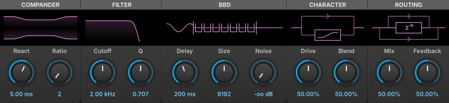
Analog BBD Delay models a bucket-brigade delay line, the chip that made analog delay pedals and rack units possible: the signal is passed from one capacitor to the next on a clock, losing a little bandwidth and gaining a little noise at every step. Delays from 10 ms to 10 seconds are available, and a compander brackets the chain as the originals did, to keep the noise floor down.
The five sections each carry a display above their knobs, and each display can be dragged: horizontally for the left knob of the section and vertically for the right, with Ctrl for finer steps.
Compander
REACT (1–50 ms) sets how quickly the compander follows the level of the signal, and RATIO (2–6) sets how hard it compresses on the way in and expands on the way out. The display draws the resulting range: Ratio closes the middle of the figure in, React steepens its ramps.
Filter
CUTOFF (20 Hz–20 kHz) sets the corner of the reconstruction filter and Q (0.500–1.000) its resonance. The filter sits inside the feedback loop, so it also damps the repeats: each pass through the loop crosses it twice, which is how the display plots it.
BBD
DELAY (10 ms–10 s) sets the delay time, in milliseconds or in bars and beats when the module is tempo-synced. SIZE sets the number of bucket stages — 1024, 2048, 4096, 8192, 16384, 32768 or 65536 — and with Delay decides the clock rate the brigade runs at: a short delay through a long chain clocks fast and stays clean, a long delay through a short one clocks slowly and darkens. NOISE sets the level of the chip’s own noise, injected ahead of the buckets. The display is a schematic of the brigade itself, one bucket per Size step, passing charge along on each tick of the clock.
Character
DRIVE (0–100 %) sets how hard the input hits the soft clipper, and BLEND (0–100 %) crossfades between the clipped path and the clean one. Saturation is applied to everything entering the delay line, the feedback included, so repeats compound it; the dry signal in the final mix is left untouched. The display shows the two paths, with the clipper’s own transfer curve drawn inside the box.
Routing
MIX (0–100 %) sets the balance between the dry and delayed signal, and FEEDBACK (0–100 %) how much of the output is returned to the input.
Diffuse Delay
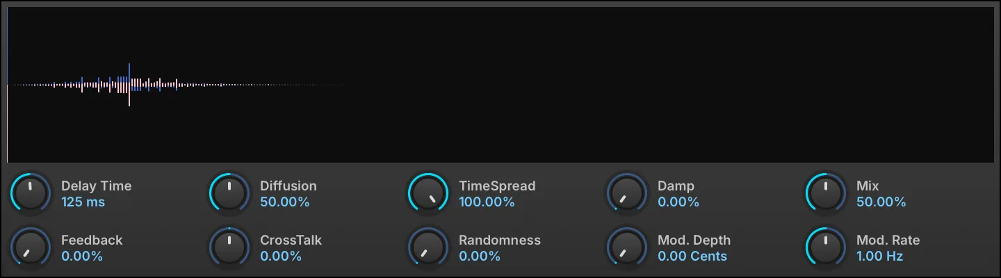
Diffuse Delay is an effect capable of morphing continuously from a pure single tap delay to a very long, dense, and lush bloom of echoes. Fantastic for scrambling voices or other instruments into an ambient wash of echoes.
DELAY TIME (0.01–1 s) sets the length of delay, in seconds (shown in ms below 1 s), or in bars/beats when tempo-synced.
DIFFUSION (0–100 %) sets the amount of diffusion (echo density), and TIMESPREAD (0–100 %) sets the time spread of the diffusion.
FEEDBACK (0–100 %) chooses the percentage of signal fed back into the module.
DAMP (0–100 %) sets the amount of damping factor for feedback loops.
RANDOMNESS (0–50 %) adds random variation to the diffusion pattern for a less regular, more natural echo texture.
NOTE: Diffuse Delay will re-calculate the time factor for producing the effect. So manipulating the Delay Time and TimeSpread controls will cut the effect for a moment. This means these parameters are not usable for modulation or automation.
CROSSTALK (−100–100 %) sets the crosstalk amount between the left and right channels of the feedback loop.
MIX (0–100 %) sets the balance between the dry (unaffected) and wet (affected) signal sent to the module’s output.
MOD. DEPTH (0–20 cents) chooses a detune amount for the delay taps, and MOD. RATE (0.1–10 Hz) sets the speed of modulation.
Dual Delay X
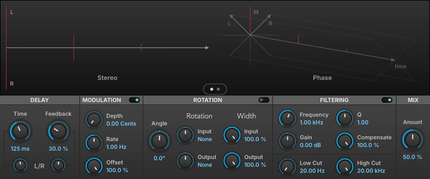
A versatile delay module with discrete channel controls for creating time-based effects. A sophisticated display visualizes changes to time, stereo and phase. Dual Delay X features built-in dispersion, diffusion, digital grit and tape saturation for a more polished sound out of the box. NOTE: Dual Delay is still available as Legacy FX.
Click the switch to toggle between Rotation and Reflection mode, applied to the stereo feedback.
Click the Switch to enable the Filtering section. A peak EQ located in the feedback loop.
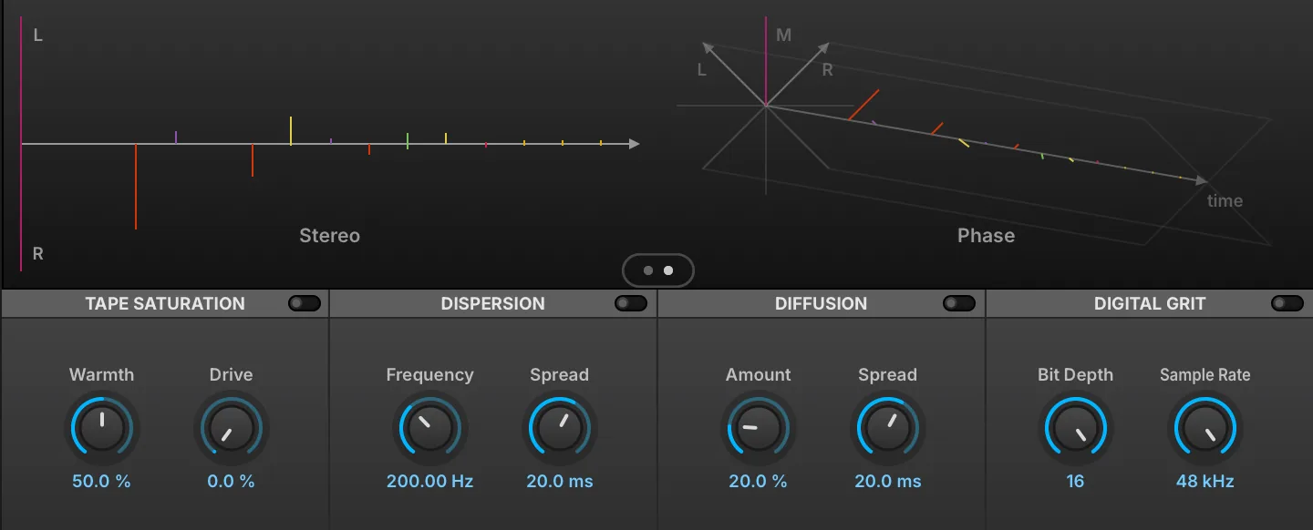
Click the Switch to toggle between main and feedback shaping controls.
TIME (0.001–5 s) sets the length of delay, in ms or bars/beats (if tempo-synced). FEEDBACK (0–100 %) chooses the percentage of signal fed back into the module. Both Time and Feedback have L/R controls that shorten one channel relative to the other: the display reads Same at the center, and L x or R x followed by a multiplier (0.10–1.00) applied to that channel only. Use 0.66 for dotted, 0.5 for half and 0.33 for triplet.
Modulation
Click the Switch to enable the Modulation section. DEPTH (0–20 cents) chooses a detune amount for the delay taps, and RATE (0.1–10 Hz) sets the speed of modulation. OFFSET (0–100 %) adjusts the phase offset of the delay line LFO.
Rotation/Reflection
ANGLE (−180 to 180) sets the rotation angle applied to the stereo feedback path.
The ROTATION section rotates the stereo field of the INPUT (−45 to 45°) and OUTPUT (−45 to 45°) signals; +45° on the input performs an L/R to M/S conversion, and −45° on the output converts back.
The WIDTH section adjusts the stereo spread of the signal INPUT (0–100 %) to the effect, and the spread of the OUTPUT (0–100 %) signal.
Filtering
FREQUENCY (20–20,000 Hz) sets the EQ frequency. GAIN (−20–20 dB) sets the EQ gain amount (+/-). Q (0.1–10) sets the filter’s bandwidth. COMPENSATE (0–100 %) sets the amount of gain reduction for EQ to avoid feedback instability. LOW CUT (20–4,000 Hz) rolls off lower frequencies, and HIGH CUT (1,000–20,000 Hz) rolls off higher frequencies. The filters affect only the wet signal; the dry signal is not filtered.
Tape Saturation
Click the Switch to enable the section. WARMTH (0–100 %) sets the amount of the pre-emphasis before saturation, and DRIVE (0–100 %) sets the saturation amount.
Dispersion
Click the Switch to enable the section. FREQUENCY (0–20,000 Hz) sets the dispersion frequency, and SPREAD (1–100 ms) sets the dispersion time in ms.
Diffusion
Click the Switch to enable the section. AMOUNT (0–100 %) sets the diffusion amount, and SPREAD (1–100 ms) sets the diffusion time in ms.
Digital Grit
Click the Switch to enable the section. BIT DEPTH (4–16) sets the bit reduction, and SAMPLE RATE sets the sample rate reduction.
Mix
AMOUNT knob sets the balance between the dry (unaffected) and wet (affected) signal sent to the module’s output.
Display
The display shows a visual representation of how the controls will affect the STEREO and PHASE output of the module.
Tape Echo

A recreation of the famous 70s tape delay.
RATE sets the rate of the delay repeats, INTENSITY (0–200 %) chooses the percentage of signal fed back into the module.
Mode
The central MODE knob selects between delay, delay + reverb, or reverb only modes.
The numeric indicators (1, 2, 3, and combinations) represent which of three discrete delay heads will be utilized.
The DELAY TIMES (0.05–0.5 s) for each head can be seen and modified via the I, II, III number boxes on the right.
The STOP button activates a tape stop effect.
REVERB GAIN (0–100 %) sets the reverb volume.
Filter
The filters shape the delayed signal only; neither the dry signal nor the reverb is filtered. BASS (−10 to 10) boosts or cuts the low frequencies, and TREBLE (−10 to 10) boosts or cuts the high frequencies.
Output
MIX (0–100 %) knob sets the balance between the dry (unaffected) and wet (affected) signal sent to the module’s output.
Track Delay

A simple time-shifting of the input using a delay.
DELAY TIME (0–5 s) sets the length of delay, in μs, ms and seconds or bars/beats (if tempo-synced).
Velvet Delay
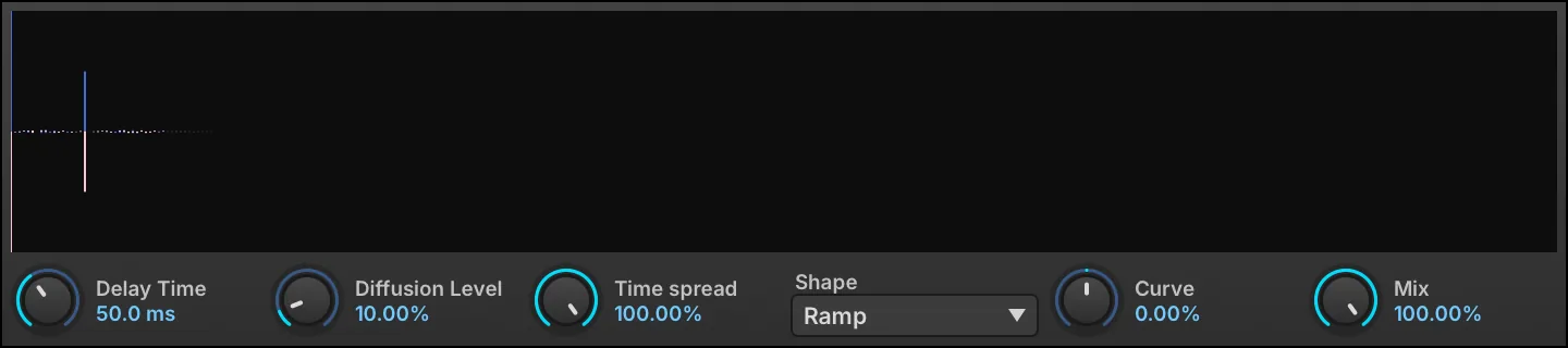
Velvet Delay is another take on morphing from a single tap delay to a smooth aura of echoes. Compared to Diffuse Delay, the emphasis is less on maximal diffuseness, but more on the smoothness of the pre and post echoes and precise control of the ratio between specular and diffuse reflections.
DELAY TIME (0.001–1 s) sets the length of delay, in seconds (shown in ms below 1 s).
DIFFUSION LEVEL (0–90 %) sets the amount of diffusion (echo density), and TIME SPREAD (10–100 %) sets the time spread of the diffusion.
SHAPE chooses the echo shape — Ramp (the default), Uniform, Exp, Ramp down, Parabolic, Inv. Parabolic or Parametric — and CURVE (−100–100 %) bends the Parametric shape toward a concave or convex ramp; it has no effect on the other six shapes.
MIX (0–100 %) sets the balance between the dry (unaffected) and wet (affected) signal sent to the module’s output.
Reverb
Bloom
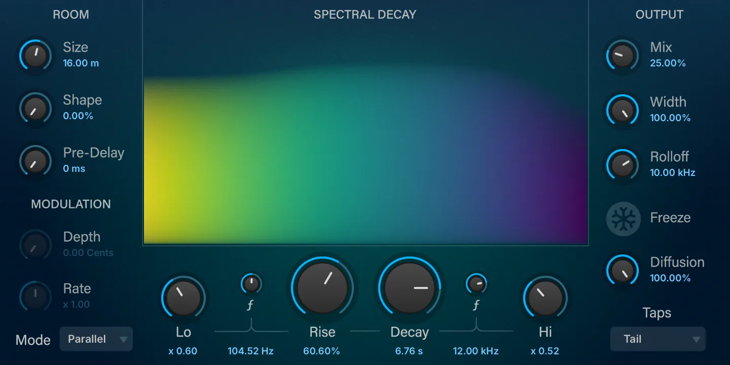
A reverb that swells into existence, building rich ambience after your initial sound. Shape the rise, depth, and decay to create lush soundscapes, evolving textures, and immersive atmospheres unique to Bloom.
The central DECAY (0.1–10) parameter scales the duration of the reverb decay; it is a multiplier, and the decay time it displays also follows Size. Low and Hi frequency bands can further tailor the decay response across frequencies. Set the decay ratio for each band (relative to the main Decay time) with LO (0.1–10) and HI (0.1–10), and the crossover frequency of each band with the small ƒ knob beside it (10–1,000 Hz for Lo, 2,000–20,000 Hz for Hi). RISE (0–100 %) controls the amount of rise time as a percentage of the current decay time; it applies in Parallel and Serial modes only, and has no effect in Single.
Room
SIZE (4–50) sets the mean room dimension in meters with continuous control (from tiny rooms to huge halls). SHAPE (0–100 %) sets the delay distribution and distortion of the room, from 0 % (highest echo density) to 100 % (highest spectral mode density).
PRE DELAY (0–250 ms) sets the amount of delay before the wet signal is heard.
Modulation
DEPTH (0–20 cents) chooses the depth of the decay modulation, in cents.
RATE (0.1–10) chooses a relative ratio for each delay line. Modulation is disabled in Parallel mode: Depth and Rate act in Single and Serial only.
Mode
Select the processing mode:
-
SINGLE: a single reverb engine, with no rise time (Rise has no effect).
-
PARALLEL: Rise time is obtained by running two slightly detuned reverb engines in parallel.
-
SERIAL: Rise time is obtained by running two slightly detuned reverb engines in sequence.
Output
MIX (0–100 %) sets the balance between the dry (unaffected) and wet (affected) signal sent to the module’s output. WIDTH (0–100 %) adjusts the stereo spread of the module’s output. ROLLOFF (2,000–20,000 Hz) sets the cutoff frequency of an overall low-pass filter to adjust the brightness of the wet signal. Enabling FREEZE will hold the current decay infinitely, until Freeze is disabled.
DIFFUSION (0–100 %) controls the amount of diffusion applied; lower amounts leave more distinct, discrete echoes, while higher amounts build a denser, smoother, more reverb-like tail.
Taps
Select the shape of the impulse response and early reflections.
Diffusion

Diffusion spreads the signal over time, creating a simple yet versatile decay with reverb-like results.
The display is the effect’s impulse response rather than its frequency response, which is flat when the effect is fully wet. It is fed opposite impulses on the two channels, so the stereo decorrelation the allpass delays produce is visible as the two traces diverge.
The DIFFUSION (0–100 %) control sets the amount of diffusion applied.
DIFFUSION START (0.1–20 ms) chooses the time delay until diffusion begins to be applied.
MIX (0–100 %) sets the balance between the dry (unaffected) and wet (affected) signal sent to the module’s output.
IReverb
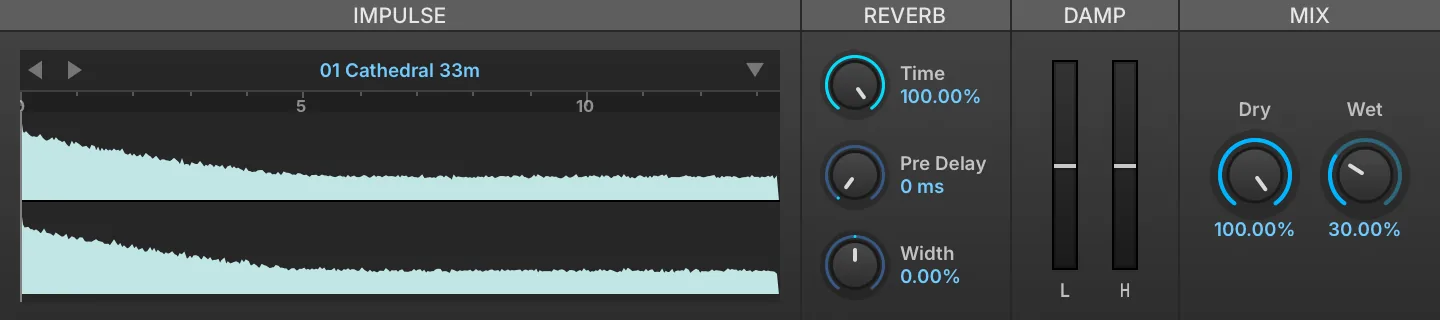
IReverb is a convolution reverb. Given an impulse response for a physical space or a piece of gear, IReverb can accurately reproduce what the input source would sound like if it were actually in that space or played through that piece of hardware.
If there is audio passing through the IReverb while parameters are being adjusted, the dry signal will be heard momentarily. This is because convolution is a processor-intensive effect and briefly muting the processed signal is necessary to avoid pops/clicks or other artifacts.
To load an IMPULSE RESPONSE, drag and drop an audio file to the sample area, or load one of the factory presets.
Reverb
TIME (10–100 %) sets the duration of the wet signal, specified as a percentage of the impulse response’s duration. PRE DELAY (0–100 ms) sets the amount of delay before the wet signal is heard.
Damp
LOW DAMP (−100–100 %) and HIGH DAMP (−100–100 %) reshape how the low or high frequencies evolve along the tail rather than filtering the output: positive values fade the band out over the decay, negative values fade it in.
Mix
DRY (0–100 %) and WET (0–100 %) knobs set the balance between the dry (unaffected) and wet (affected) signal sent to the module’s output.
Impulse Files
To save the currently loaded impulse, choose SAVE IMPULSE to save the current file or SAVE IMPULSE AS to save as a new file.
WIDTH (−100–100 %) adjusts the stereo width of the impulse response. At negative values, the stereo image is narrowed, collapsing to mono at −100 %.
SparkVerb
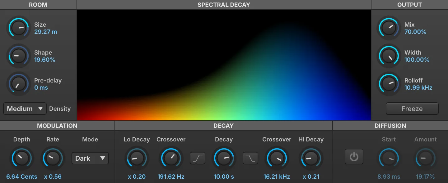
SparkVerb is a unique and versatile algorithmic reverb, centered around a frequency-based spectral display. The sound can be shaped with separate frequency bands, or adjusted globally.
The central DECAY (0.1–10) parameter scales the duration of the reverb decay; it is a multiplier, and the decay time it displays also follows Room Size. Low and Hi frequency bands can further tailor the decay response across frequencies. Choose the frequency for each band with LO XOVER (10–1,000 Hz) and HI XOVER (2,000–20,000 Hz), and set the decay ratio (relative to the main Decay time) with LO DECAY (0.1–10) and HI DECAY (0.1–10). If you would rather cut the Low or Hi bands instead, use DECAY LOW-CUT and DECAY HI-CUT.
Room
ROOM SIZE sets the size of the simulated space, from small rooms (4 meters) to very large rooms (50 meters). SHAPE (0–100 %) sets the delay distribution and distortion of the room, from 0 % (highest echo density) to 100 % (highest spectral mode density). PRE DELAY (0–100 ms) sets the amount of delay before the wet signal is heard. DENSITY changes how dense the reflections will be; lower values will be more like distinct echoes.
Modulation
DEPTH (0–20 cents) chooses the depth of the decay modulation, in cents. RATE (0.25–4) chooses a relative ratio, from 1/4 to 4x, for each delay line. MODE sets the modulation interpolation style; choose from Dark (default; some high-frequency decay damping), Lo-Fi (more high frequency diffusion), or Bright (more precise high-frequency response, but more processor intensive).
Diffusion
DIFFUSION ON/OFF toggles the short-term diffusion option. When enabled, DIFFUSION START (1–10 ms) sets the delay time until the diffusion is heard, and AMOUNT (0–100 %) sets how much diffusion will be applied.
Output
MIX (0–100 %) sets the balance between the dry (unaffected) and wet (affected) signal sent to the module’s output. WIDTH (0–100 %) adjusts the stereo spread of the module’s output. ROLLOFF (2,000–20,000 Hz) sets the cutoff frequency of an overall low-pass filter to adjust the brightness of the wet signal. Enabling FREEZE will hold the current decay infinitely, until Freeze is disabled.
Modulation
Analog Chorus

Analog Chorus is a chorus module that is inspired by a popular analog effects pedal.
SPEED (0.1–10 Hz) sets the speed of the modulation, WIDTH (0–6) adjusts the width of the stereo spread, and INTENSITY (0–6) sets the depth of the effect.
TRANSIENT ENHANCEMENT (0–10) adjusts how much transients are affected by the module. Higher values allow for more prominent, unmodulated transients.
Analog Flanger

Analog Flanger is a flanger module that is inspired by a popular analog effects pedal.
SPEED (0.1–10 Hz) sets the speed of the modulation, and INTENSITY (0–6) sets the depth of the effect. WIDTH (0–6) adjusts the delay times and modulation depth to increase the stereo width of the effect.
TRANSIENT ENHANCEMENT (0–10) adjusts how much transients are affected by the module. Higher values allow for more prominent, unmodulated transients.
Analog BBD Chorus
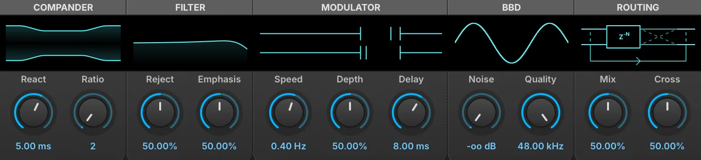
Analog BBD Chorus runs the same bucket-brigade line as the delay at chorus lengths, in the spirit of the 80s studio rack units. Its modulation is deliberately anti-phase across the two channels: the delay time of the pair moves apart and back together rather than up and down as one, which widens the image without the warble a shared sweep produces.
As with the delay, each section’s display can be dragged — horizontally for the left knob, vertically for the right.
Compander
REACT (1–50 ms) and RATIO (2–6) set the speed and the ratio of the compander bracketing the chain, exactly as they do on the delay.
Filter
REJECT (0–100 %) sets the anti-alias filter relative to the BBD’s own clock rather than in hertz: at 0 % the corner sits at the clock rate, at 100 % two octaves below it, never above 22 kHz, so the filter follows whatever Quality is set to. EMPHASIS (0–100 %) sets its resonance. The display plots the curve against a fraction of the clock’s Nyquist rather than a frequency axis, for the same reason.
Modulator
SPEED (0.05–2 Hz) sets the rate of the triangle modulator and DEPTH (0–100 %) how far it swings the clock, up to ±30 % of its rate. DELAY (1–30 ms) sets the delay the modulation moves around. The display animates the two channels as markers traveling in opposite directions along the delay axis, in real time.
BBD
QUALITY (1–48 kHz) sets the clock rate the brigade runs at, and the number of stages follows from it. Lowering it coarsens the sampling audibly — the display draws the staircase getting rougher. NOISE sets the level of the chip’s own noise.
Routing
MIX (0–100 %) sets the balance between the dry and processed signal. CROSS (0–100 %) adds each channel’s wet signal, inverted and low-shelved, into the other channel’s output: a width control in the manner of the Dimension units rather than a channel swap, canceling the middle of the wet signal as it is raised while leaving the bass in place.
Ensemble 505

Ensemble 505 is an ensemble chorus effect, inspired by the ensemble effect section of a popular synth.
MODE chooses the style of ensemble: I is the plain ensemble, II adds a light fast secondary modulation on two of the four delay lines, and III instead adds feedback to the delay lines, for the most pronounced effect. TONE (3,000–10,000 Hz) sets the cutoff of the low-pass filtering applied along the ensemble path, both to the signal entering the delay lines and to each delay line output.
MIX (0–100 %) sets the balance between the module’s input path and the ensemble output. The input path is not the untouched signal: it is summed to mono and low-pass-filtered by TONE before the blend, so at 0 % the module still outputs a mono, filtered version of the input.
Flanger

Flanger is a classic flanger effect, where the input signal is delayed with a variable time delay and fed back onto itself.
SPEED (0.01–10 Hz) sets the speed of the modulation (in Hz, or bars/beats if tempo-synced).
DELAY TIME (0–20 ms) sets the base delay the modulation sweeps around. Note: the value display currently reads 50 times too high (for example, 200 ms means 4 ms). DEPTH (0–100 %) sets the depth of the effect.
FEEDBACK (0–100 %) sets the percentage of signal fed back into the module.
MIX (0–100 %) sets the level of the flanged signal added to the module’s output. It is not a dry/wet balance: the dry signal always passes at full level, so raising Mix adds the effect on top of it rather than replacing it.
Freq Shifter
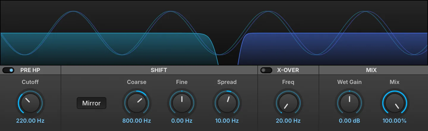
Freq Shifter is a linear frequency shifter effect. Shifts all frequencies in the spectrum by a set amount (Hz) for interesting morphing effects, widening, sound thickening and repitching inharmonic sounds like drums.
Pre HP
Click the Switch to enable the section.
CUTOFF (20–20,000 Hz) sets the cutoff frequency of the pre-high-pass -24 dB/oct Butterworth filter, which gets rid of the low end when the shift is too high.
Shift
MIRROR adds extra content in the low end when enabled. With a positive shift, partials below the shift amount also appear mirrored at (shift − frequency). With a negative shift, partials pushed below 0 Hz fold back as mirrored low frequencies instead of being removed. With MIRROR off, these components are discarded. NOTE: with MIRROR off, extreme positive shifts produce aliasing.
COARSE / FINE shifts the spectrum up or down by a constant frequency in Hz such that harmonic sounds become inharmonic.
SPREAD (−200–200 Hz) adds a shift difference between the channels. Even a slight difference can be used to get a full, wide stereo effect.
X-over
Click the Switch to enable the section. FREQ (20–20,000 Hz) sets the split frequency of a -24 dB/oct crossover filter to allow preservation of the original low-frequency content.
Mix
WET GAIN (−12–12 dB) sets the gain of the wet signal. MIX (0–100 %) sets the dry/wet amount.
Granulizer
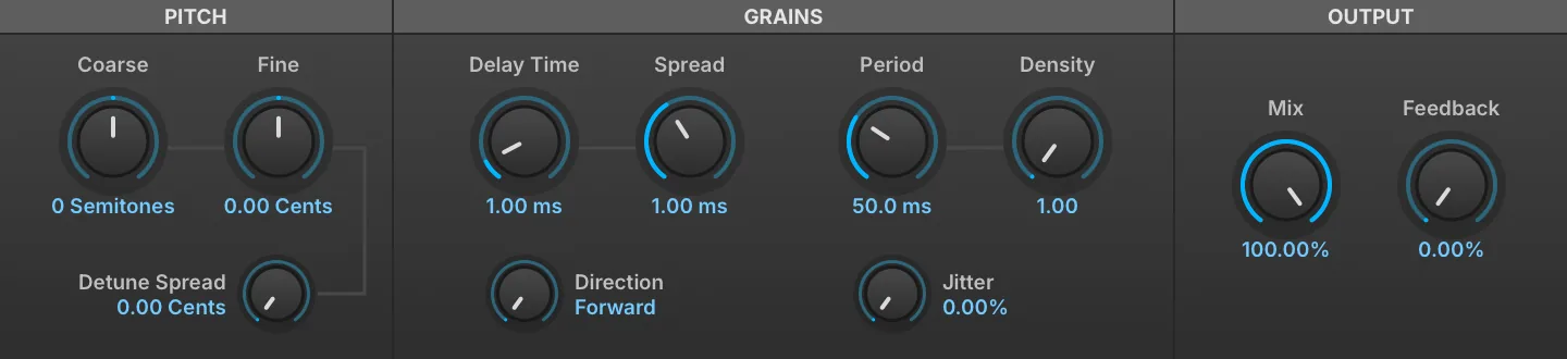
Granulizer can be thought of as the effect equivalent to Falcon’s granular oscillator, and is exceptional for creating pads, textures, and ambiance. Instead of splicing grains of sound taken from audio files, grains are extracted directly from audio in real time. It is possible to shape sound in multiple ways for kaleidoscopic sound deconstruction and reconstruction.
COARSE / FINE shifts the grain pitch in semitones and cents. DETUNE SPREAD (0–100 cents) adds a detune effect to each grain.
Grains
DELAY TIME (0–2 s) sets how far back in the captured audio the grains are read, in seconds, and SPREAD (0–0.005 s) adds the variation of the delay time. DIRECTION sets the direction of scrubbing: Forward, Backward, Alternate and Random.
PERIOD (0.01–2 s) sets the duration of the grains. DENSITY (1–10) determines how many grains overlap at any time, two grains at 1.00 and up to twenty at 10.00. Raising it thickens the overlap, with a harmonic result similar to a chorus or sometimes a ring modulator. JITTER (0–100 %) varies the consistency of grain playback timing.
Output
MIX (0–100 %) sets the dry/wet amount. FEEDBACK (0–100 %) sets the percentage of signal fed back into the module.
DENSITY COMPENSATION (0–100 %) sets how the gain change caused by overlapping grains is compensated, from a DC-summing assumption at 0 % to a white-noise-summing one at 100 %. It is not on the module’s front panel; reach it from the parameter list or as a modulation target.
Phasor
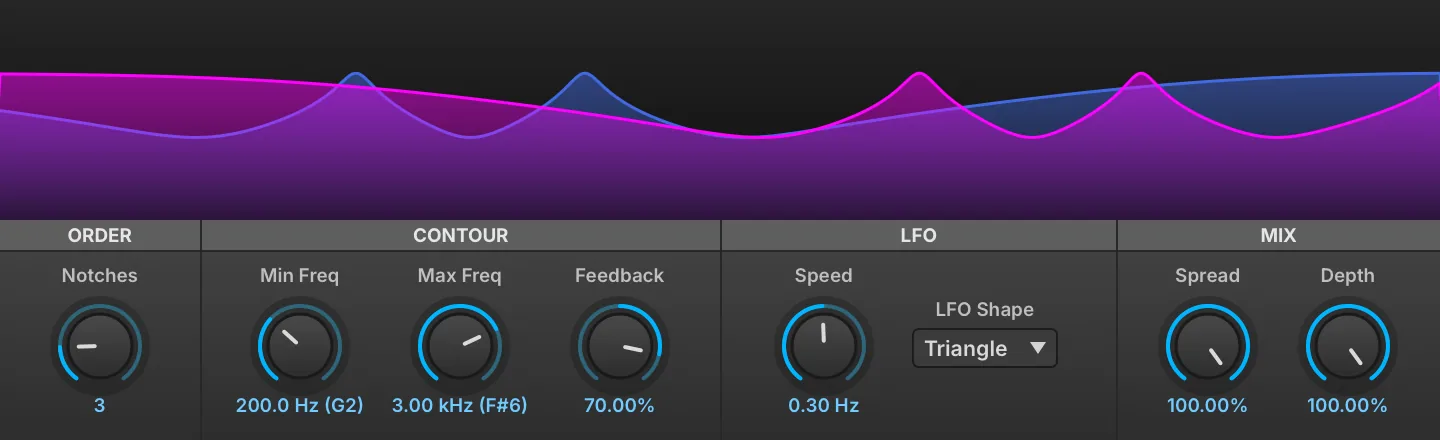
Phasor is a variable 12-order automatic phaser effect.
NOTCHES (1–12) changes the number of filters in sequence which correlates to the number of peaks and valleys you see displayed in the visualizer.
Mix
SPREAD (0–100 %) emphasizes the stereo effect. DEPTH (0–100 %) sets the wet/dry mix amount.
Contour
In Phasor an LFO sweeps between two variable frequencies, these are controlled with MIN FREQ (20–20,000 Hz) and MAX FREQ (20–20,000 Hz).
FEEDBACK (−99–99 %) controls the amount of the effected signal reinjected.
LFO
SPEED sets the speed of the LFO, which defaults to a free-running frequency between 0.01 Hz and 10.00 Hz.
Toggling the TEMPO SYNC icon in the header allows the LFO to be synced to the host clock and set between 1/64 tri and 32x.
LFO SHAPE controls the shape of the LFO which can be set to TRIANGLE, SINE, S&H or RANDOM.
Rotary
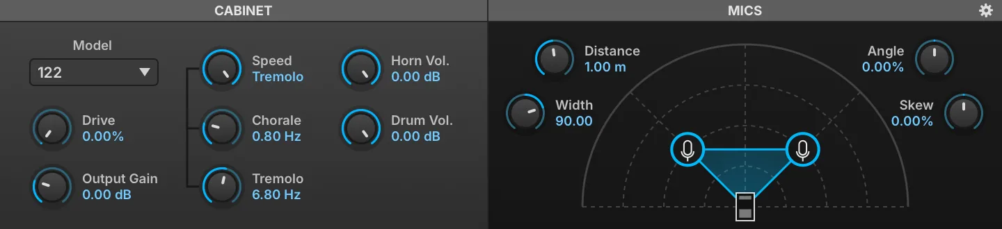
Rotary is a highly customizable speaker emulation effect modeled after the classic two-way rotating designs created for electric organs in the 1940s.
MODEL changes the cabinet type. DRIVE (0–100 %) sets the amount of overdrive in the cabinet circuit. GAIN (0–4) controls the amount of output gain.
Seven cabinets are available: 122, 145, 30, 722, 760, 950 and 16, each with its own enclosure dimensions.
SPEED sets the rotary style: BRAKE = none, CHORALE = slow speeds, TREMOLO = fast speeds.
Chorale and Tremolo speeds are controllable with the CHORALE (0.1–3 Hz) and TREMOLO (3–10 Hz) knobs below.
Mics
DISTANCE (0.1–2 m) sets the distance of the mics to the cabinet. ANGLE (−100–100 %) rotates the pair of mics around the cabinet, away from the front axis.
WIDTH (−180 to 180) sets the angular separation of the two mics. SKEW (−100–100 %) sets the disparity in distance between mics and cabinet. If set high, one mic will be close and the other will be far from the speaker.
BACKPANEL (COGWHEEL ICON) opens the settings to access the back panel controls.
HORN VOL (0–1) adjusts the rotating horn level. DRUM VOL (0–1) adjusts the rotating drum level.
Back Panel
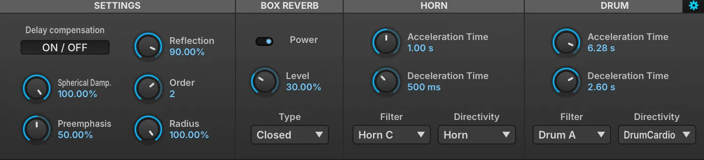
-
Horn: standard directivity with deflector.
-
Omni: No AM
-
Cardio: Classic polar pattern (sound cancellation when horn is off-axis).
-
SoftCardio: Softer version of cardioid (with no off-axis cancellation).
-
Unipolar: heavy pulsating tone (pronounced AM).
-
Drum: directivity with fewer side lobes - less wide sound (usable on horn).
-
Drum Cardio: standard drum directivity (usable on horn).
-
Drum Cardio 2: More pronounced off-phase side lobes (drum exclusive).
-
Drum Cardio 3: Most pronounced off-phase side lobes (drum exclusive).
Settings
DELAY COMPENSATION removes latency caused by mic distance.
SPHERICAL DAMPENING (0–100 %) controls the amount of attenuation that is applied to reflections with propagation distance.
PREEMPHASIS (0–100 %) controls the amount of preemphasis that is applied before amplifier drive. REFLECTION (0–100 %) controls how reflective the cabinet walls are, higher values giving stronger internal reflections.
ORDER (0–3) controls the order of ray traced early reflections for the horn; the drum is always limited to first order. RADIUS (0–100 %) changes the length of horn and drum speakers.
Box Reverb
POWER enables diffusion. LEVEL (0–100 %) sets the amount of diffusion. TYPE selects the enclosure used for the diffusion: Open or Closed back.
Horn
ACCELERATION TIME (0.1–10 s) sets the horn acceleration time. DECELERATION TIME (0.1–10 s) sets the horn deceleration time. FILTER sets the horn frequency response. DIRECTIVITY chooses the horn directivity type.
The horn FILTER offers Off, Horn A, Horn B and Horn C.
Drum
ACCELERATION TIME (0.1–10 s) sets the drum acceleration time. DECELERATION TIME (0.1–10 s) sets the drum deceleration time. FILTER sets the drum frequency response. DIRECTIVITY chooses the drum directivity type.
The drum FILTER offers Off and Drum A.
Thorus
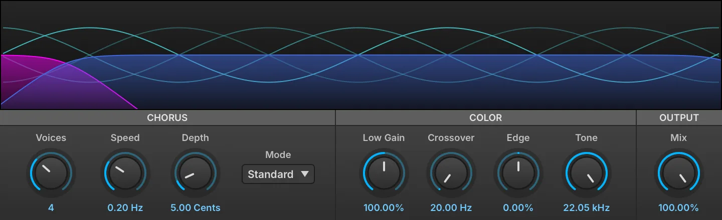
Thorus is a variable 8-voice chorus that provides an exceptionally clear effect and a number of useful color controls.
VOICES sets the number of chorus voices utilized from 2–8.
SPEED sets the chorus frequency from 0.1 Hz to 1.0 Hz. DEPTH sets the pitch modulation depth from 1 to 40 cents.
MODE influences the perceived stereo effect and can be set to either Standard or Wide.
Color
CROSSOVER (20–5,000 Hz) sets the crossover frequency between the Low (pass-through) signal and the High (chorused) signal. LOW GAIN (0–200 %) controls the level of the low (pass-through) signal.
EDGE (−100–100 %) controls the feedback amount of the High (chorused) signal. TONE (2,000–22,050 Hz) controls the frequency of the low-pass filter.
Output
MIX (0–100 %) controls the wet/dry mix amount of the effect.
TRIM (−12–0 dB) attenuates the module’s output, to compensate for the level the chorus adds. It is not on the module’s front panel; reach it from the parameter list or as a modulation target.
Filter
Analog Filter

Analog Filter is a multimode filter inspired by the filter section found on a popular American analog synth.
MODE chooses the type of filter: low-pass (LP), high-pass (HP), or band-pass (BP).
CUTOFF (20–20,000 Hz) sets the frequency for the filter; the note name corresponding to the frequency is also displayed, for example, 2.00 kHz (B5).
RESONANCE (0–100 %) adjusts how much the cutoff frequency is emphasized.
KEY TRACKING (0–100 %) changes how the cutoff frequency is adjusted relative to the note played.
Biquad Filter

The classic Swiss Army knife multimode filter.
MODE chooses the type of filter: high-pass (HP), low-pass (LP), band-pass (BP), or notch.
CUTOFF (20–20,000 Hz) sets the frequency for the filter; the note name corresponding to the frequency is also displayed, for example, 2.00 kHz (B5).
RESONANCE (0–100 %) adjusts how much the cutoff frequency is emphasized.
KEY TRACKING (0–100 %) changes how the cutoff frequency is adjusted relative to the note played.
Brickwall Filter

Brickwall Filter is a filter with a steep slope, from 24 dB/oct up to 96 dB/oct, for “brickwall” filtering beyond the cutoff frequency.
CUTOFF (20–20,000 Hz) sets the frequency for the filter; the note name corresponding to the frequency is also displayed, for example, 2.00 kHz (B5).
TYPE chooses the type of filter: low-pass (LP) or high-pass (HP).
SLOPE sets how sharply the filter slopes downward at the cutoff frequency, in dB per octave: 24, 48 or 96 dB/oct (96 dB/oct by default).
SOFT BYPASS lets the signal through unfiltered, crossfading over 100 ms when switched. This is an ideal way to bypass the effect while playing, as the regular bypass can pop or click if switched during playback.
Comb Filter

A classic comb filter, where a time delayed version of the signal is fed back into itself and added or subtracted. This results in unique frequency peaks and valleys where the phases of the signals combine or cancel each other out.
MODE chooses the type of comb filter applied: Plus (frequencies are added) or Minus (frequencies are subtracted).
CUTOFF (20–20,000 Hz) sets the frequency for the filter; the note name corresponding to the frequency is also displayed, for example, 2.00 kHz (B5).
RESONANCE (0–100 %) adjusts how much the cutoff frequency is emphasized.
KEY TRACKING (0–100 %) changes how the cutoff frequency is adjusted relative to the note played.
ALGORITHM chooses how the comb is rendered. Modern, the default, interpolates the delay with an allpass filter, smooths changes to the delay and the feedback, and normalizes the level, so the output stays bounded however the filter is modulated. Classic is the original comb sound. Programs saved with earlier versions load in Classic, so they keep their sound.
Crossover Filter

Crossover Filter has a selectable filter type and variable crossover frequencies for the affected band.
When Low Pass is chosen, only the Low-Mid knob can be adjusted; the Mid-High Freq knob is disabled.
Likewise, when High Pass is chosen, only the Mid-High knob can be adjusted.
Both knobs can be adjusted when Band Pass is chosen.
TYPE chooses the type of filter: low-pass (LP), high-pass (HP), or band-pass (BP).
LOW-MID FREQ (20–20,000 Hz) and MID-HIGH FREQ (20–20,000 Hz) set the frequency boundaries for the crossover.
Digital Filter

Digital Filter is a multi-mode filter with variable slope ranging from 6 to 96 dB/oct, spread and key tracking.
MODE sets the filter mode and filter slope. Click the upper button to switch the filter mode: low-pass, high-pass, band-pass, notch, low-shelf, high-shelf and peak, and the lower button to set the filter slope: 6, 12, 18, 24, 36, 48, 72 or 96 dB/oct.
FREQUENCY (10–22,000 Hz) sets the frequency for the filter.
KEY TRACKING (−100–100 %) changes how the cutoff frequency is adjusted relative to the note played. SPREAD (−48–48 st) emphasizes the stereo effect.
Q adjusts the filter resonance, and has no effect on the 6 dB/oct slope. GAIN (−30–30 dB) sets the boost or cut applied by the low-shelf, high-shelf and peak modes, and is inactive for the other modes.
BANDWIDTH (0.01–10 oct) sets the width of the band, and applies to the band-pass, notch and peak modes only.
Formant Crusher

A screaming lo-fi take on formant filtering, (ab)using a resonant filter and a bitcrusher to generate vocal formants; a perfect fit to spice up your talking basses!
FORMANT (−100–100 %) shifts the formant frequencies up or down by up to one octave.
BITE (0–100 %) hardens the crusher, fading its output from smoothed steps to raw sample and hold.
Q (10–20) sets the filter’s width.
Shape
Two vowel sounds can be chosen for the filter, set via FILTER A and FILTER B, while the blend of the two is controlled via MORPH (0–100 %).
Mix
AMOUNT sets the balance between the dry (unaffected) and wet (affected) signal sent to the module’s output.
LPG

LPG is a low-pass gate built on a model of the vactrol cell used in the classic West Coast designs. A single control voltage lights the cell’s lamp, and the photoresistor it illuminates opens the filter and raises the level together, with the slow, uneven attack and the long relaxation of the component itself. Notes taper into silence rather than being cut off, which is where the plucked, resonant character of the circuit comes from.
MODE chooses what the cell drives: Lowpass filters without touching the level, VCA changes the level without touching the tone, and Both opens brightness and level together, as the original circuit does.
RESO (0–100 %) emphasizes the moving filter corner. It applies to the filter alone, and so is available in Lowpass mode only.
GATE (0–100 %) opens the gate by hand. It is the control voltage the cell sees, so it raises brightness and level together according to the Mode setting, and it responds with the lag of the component rather than instantly.
SENS (0–5 V) scales the control voltage reaching the cell at a fully open gate, setting how far the gate travels and how hard it drives the cell.
AUTO drives the gate from note on and note off, in place of the Gate control, which is then unavailable. This is what turns the module into a per-note gate rather than a manual or modulated one. It follows note events, so it only does anything where the effect sees them: on a keygroup insert, which runs once per voice. Placed higher in the hierarchy — on a layer, program or part — there are no notes for it to follow and the gate does not move.
VEL scales that automatic gate by the velocity of the note instead of opening it fully, so a harder note opens the gate further. It is available only with Auto enabled.
The display at the right traces a single gate event as the cell produces it, its height standing for level and its color for brightness — a magnitude response cannot show what a low-pass gate does, since the filter and the level move together. The CV bar between Gate and Sens reads the control voltage reaching the cell, in volts.
Ladder

Our take on the classic East Coast low-pass filter sound, capable of everything from smooth tones to ripping sweeps.
RESONANCE TRIM (0–50 %) adds feedback on top of the Resonance setting, up to self-oscillation.
GAIN COMPENSATION (0–100 %) makes up the level lost as resonance increases.
OVERSAMPLING TYPE chooses the sample rate conversion used: Simple, or Precise for cleaner filtering at a higher CPU cost.
CUTOFF (20–20,000 Hz) sets the frequency for the filter; the note name corresponding to the frequency is also displayed, for example, 2.00 kHz (B5).
RESONANCE (0–100 %) adjusts how much the cutoff frequency is emphasized.
VOLTAGE REF (0.01–1 V) sets the level driven into the transistor ladder; higher values saturate earlier.
SCOPE shows the output (blue line) and input (pink square wave).
OVERSAMPLING (2–4) sets the internal oversampling factor; the filter always runs oversampled, and higher factors reduce aliasing at a higher CPU cost.
KEY TRACKING (0–100 %) changes how the cutoff frequency is adjusted relative to the note played.
Lowpass 12

Lowpass 12 is a 12 dB/octave low-pass filter.
CUTOFF (20–20,000 Hz) sets the frequency for the filter; the note name corresponding to the frequency is also displayed, for example, 2.00 kHz (B5).
RESONANCE (0–100 %) adjusts how much the cutoff frequency is emphasized.
KEY TRACKING (0–100 %) changes how the cutoff frequency is adjusted relative to the note played.
Lowpass 24

Lowpass 24 is a 24 dB/octave low-pass filter.
CUTOFF (20–20,000 Hz) sets the frequency for the filter; the note name corresponding to the frequency is also displayed, for example, 2.00 kHz (B5).
RESONANCE (0–100 %) adjusts how much the cutoff frequency is emphasized.
KEY TRACKING (0–100 %) changes how the cutoff frequency is adjusted relative to the note played.
One Pole

A gentle and very efficient 6 dB/octave low-pass or high-pass filter. The most efficient of all filters by far.
MODE chooses the type of filter: low-pass or high-pass.
CUTOFF (20–20,000 Hz) sets the frequency for the filter; the note name corresponding to the frequency is also displayed, for example, 2.00 kHz (B5).
KEY TRACKING (0–100 %) changes how the cutoff frequency is adjusted relative to the note played.
Phasor Filter
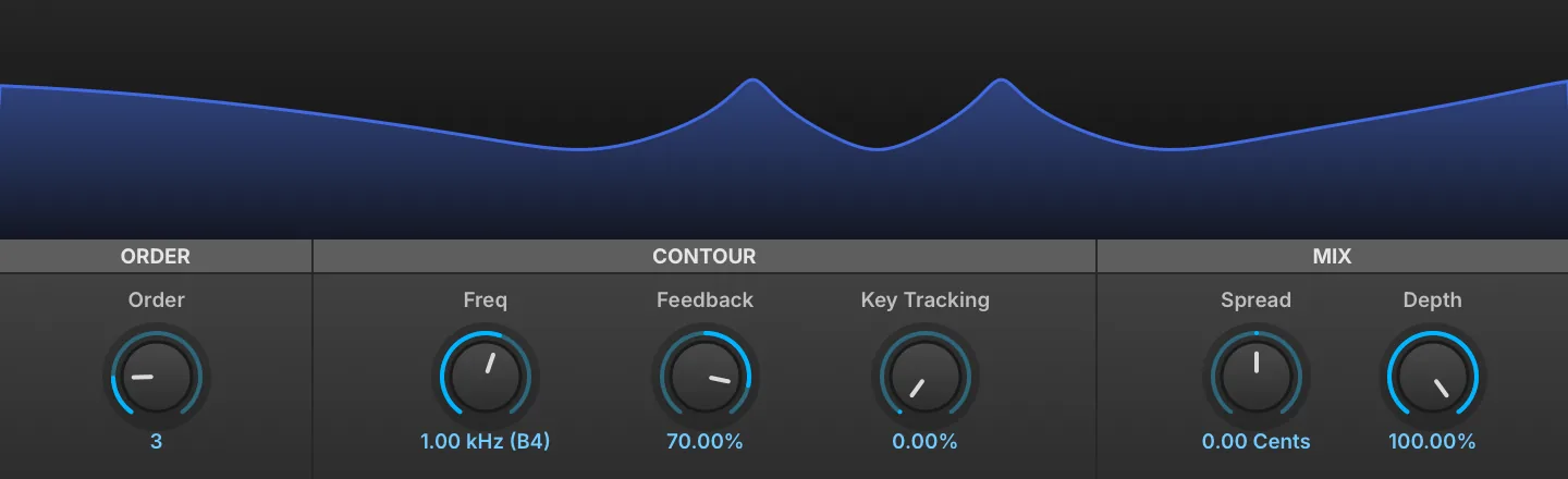
A manual version of the Phasor effect.
ORDER (1–12) changes the number of filters in sequence which correlates to the number of peaks and valleys you see displayed in the visualizer.
CONTOUR FREQ (20–20,000 Hz) sets the filter frequency.
FEEDBACK (−99–99 %) controls the amount of the effected signal reinjected.
KEY TRACKING (0–100 %) changes how the cutoff frequency is adjusted relative to the note played.
Mix
SPREAD (−12–12 st) emphasizes the stereo effect. DEPTH (0–100 %) controls the wet/dry mix amount.
CUTOFF MODE chooses how the notches are spaced: Default scales their spacing with the Order setting, Symmetric keeps them centered on the Freq setting.
Rez Filter

Rez Filter is inspired by the filter section found on a popular Japanese synth.
MODE chooses the type of filter: low-pass (LP), high-pass (HP), or band-pass (BP).
CUTOFF (20–20,000 Hz) sets the frequency for the filter; the note name corresponding to the frequency is also displayed, for example, 2.00 kHz (B5).
RESONANCE (0–100 %) adjusts how much the cutoff frequency is emphasized.
KEY TRACKING (0–100 %) changes how the cutoff frequency is adjusted relative to the note played.
SVF

SVF is a second-order (12 dB/oct) zero-delay-feedback state variable multimode filter with a built-in saturator.
FILTER MODE chooses the type of filter: low-pass (LP), high-pass (HP), band-pass (BP), peak, or notch.
CUTOFF (20–20,000 Hz) sets the frequency for the filter; the note name corresponding to the frequency is also displayed, for example, 2.00 kHz (B5). RESONANCE (0–100 %) adjusts how much the cutoff frequency is emphasized. KEY TRACKING (0–100 %) changes how the cutoff frequency is adjusted relative to the note played. DRIVE MODE chooses the style of overdrive, linear or soft.
Sallen-Key Filter

A circuit-modeled second-order single op-amp nonlinear Sallen-Key low-pass filter with controllable asymmetric clipping and power supply starvation.
CUTOFF (20–20,000 Hz) sets the frequency for the filter; the note name corresponding to the frequency is also displayed, for example, 1.00 kHz (B4).
RESONANCE (0–100 %) adjusts how much the cutoff frequency is emphasized.
KEY TRACKING (0–100 %) adjusts how much the cutoff frequency is adjusted relative to the note played.
SYMMETRY (−100–100 %) shifts the saturation symmetry between the two diodes, affecting the even/odd harmonic ratio.
RANGE (0–15) sets the saturation range.
OUTPUT chooses where the signal is tapped from the circuit: Soft takes it at the filter capacitor, Hard at the op-amp output, which tracks the clipping stage more closely.
Steiner Filter

Steiner Filter is a circuit-modeled multimode filter based on the Steiner-Parker design, whose input network feeds low-pass, band-pass and high-pass paths into a single saturating feedback loop. It offers thirteen fixed responses, from the usual second-order shapes to first-order and shelving variants, and five morphing ones: a free blend over the low-pass, band-pass and high-pass triangle, and four that sweep a single path across it.
CUTOFF (20–20,000 Hz) sets the frequency for the filter; the note name corresponding to the frequency is also displayed, for example, 2.00 kHz (B5).
RESONANCE (0–100 %) adjusts how much the cutoff frequency is emphasized; high settings make the filter ring and eventually self-oscillate.
KEY TRACKING (0–100 %) changes how the cutoff frequency is adjusted relative to the note played.
MODE chooses the response of the filter: LP, BP, HP, HP raw, Notch, Allpass, Peak, Low Shelf, High Shelf, LP1, HP1, LP Notch, HP Notch, Morph, LP-BP-HP, LP-HP, Tilt or LP1-HP1 (LP by default).
GAIN (−24–24 dB) sets the amount of boost or cut, and applies to the Peak, Low Shelf and High Shelf modes only.
DEPTH (−80–0 dB) sets the far-side gain in the LP Notch and HP Notch modes, the level the response settles to beyond the notch. At 0 dB the notch sits on the cutoff frequency; lower values move it away from the cutoff (upward in LP Notch, downward in HP Notch), and at −80 dB it lies 100 times away, so the filter behaves as a plain low-pass or high-pass.
MORPH LP, MORPH BP and MORPH HP (0–100 %) set the weight of each response in the blend used by the Morph mode; one control at full with the other two at zero reproduces that response exactly.
In Morph mode the display carries a triangle instead of the response alone, with low-pass at the bottom left, band-pass at the top and high-pass at the bottom right. Dragging the handle inside it sets the three weights at once, and the middle of each edge is marked with the response the blend reproduces there: LP1 between low-pass and band-pass, HP1 between band-pass and high-pass, and notch between low-pass and high-pass.
MORPH (0–100 %) is the position for the four one-dimensional morph modes, which sweep a single path rather than the whole triangle: LP-BP-HP travels from low-pass through band-pass to high-pass, LP-HP and LP1-HP1 run between their two endpoints at second and first order, and Tilt tips the spectrum from one side to the other, passing flat at 50 %.
SYMMETRY (−100–100 %) shifts the saturation symmetry between the two clipping thresholds, affecting the even/odd harmonic ratio.
RANGE (0–15) sets the headroom before the feedback path clips; lower values starve the circuit and distort sooner.
MODEL chooses between Ideal, a normalized response with no circuit coloration, and Circuit, which adds the coloration and makeup gain of the real input and feedback resistances (Circuit by default).
COUPLING (0–100 %) sets the ratio between the feedback and input resistances of the Circuit model, and has no effect on the Ideal model.
SOLVER chooses the integration scheme used for the saturating loop: Linear leaves the saturation out entirely, Linearly Implicit is the default, and Fixed Point and Newton trade CPU for accuracy.
UVI Filter

UVI Filter is a filter that is continuously adjustable between low-pass and high-pass modes.
CUTOFF sets the type and amount of filter. At the center position, no filter is applied. To the right of center, a high-pass filter is applied, and further to the right raises the cutoff frequency. Likewise, further left of center applies a low-pass filter and drops the cutoff frequency. The Q (0–1) control sets the filter’s shape.
MAPPING MODE sets the law used to map the CUTOFF control: use Standard for new patches, while presets saved by older versions of MachFive or UVI Player load with Legacy 1 or Legacy 2, which reproduce their original cutoff and Q curves.
VCF-20

Emulation of the MS-20 VCF filter (rev-2), single version with HP / LP morphing.
HP/LP MORPH (0–100 %) sets the balance between the high- and low-pass filters.
CUTOFF (20–20,000 Hz) sets the cutoff frequency of the filters.
PEAK (0–100 %) sets the resonance of the filter.
TRIM (0–100 %) adjusts the resonance shape.
VOLTAGE REF (0.5–5) sets the reference voltage of the unit.
KEY TRACKING (0–100 %) adjusts how the cutoff frequency is adjusted relative to the active note.
VCF-20 Dual
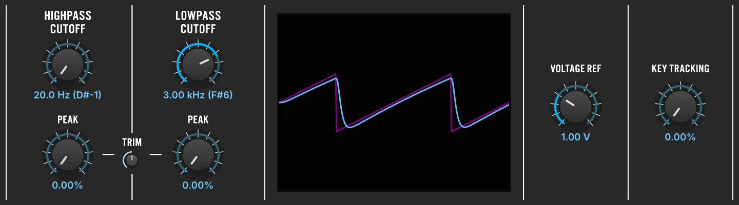
Emulation of the MS-20 VCF filter (rev-2), dual version with discrete LP and HP filters.
High Pass Filter
CUTOFF (20–20,000 Hz) sets the cutoff frequency of the filter. PEAK (0–100 %) sets the resonance of the filter.
Low Pass Filter
CUTOFF (20–20,000 Hz) sets the cutoff frequency of the filter. PEAK (0–100 %) sets the resonance of the filter.
TRIM (0–100 %) adjusts the resonance shape for both the high- and low-pass filters.
VOLTAGE REF (0.5–5) sets the reference voltage of the unit.
KEY TRACKING (0–100 %) adjusts how the cutoff frequency is adjusted relative to the active note.
VCF-4023

A virtual analog emulation of the ARP 4023 VCF circuit (as found in ARP Odyssey rev1) featuring OTA saturation and self-oscillation.
CUTOFF (20–20,000 Hz) sets the cutoff frequency of the filter.
RESONANCE (0–100 %) adjusts how much the cutoff frequency is emphasized.
VOLTAGE REF (1–15) sets the reference voltage of the unit.
SCOPE shows the output (blue line) and input (pink square wave).
HP FREQ (0–100 %) sets the cutoff frequency of the high-pass filter.
KEY TRACKING (0–100 %) adjusts the cutoff frequency relative to the active note.
OVERSAMPLE enables oversampling (2x/3x/4x) for the filter, providing higher precision at the cost of increased CPU utilization.
The parameter list holds three more: OTA SAT. and OPA SAT., both on by default, model the saturation of the two amplifier stages, and turning either off linearizes that stage. ALT. OUTPUT, off by default, takes the signal from the other tap of the filter chain.
Vowel Filter

Vowel Filter is a dual filter version of the classic talkbox effect.
MODE chooses the style of filter: low-pass (LP2), band-pass (BP2), or high-pass (HP2). Two vowel sounds can be chosen for the filter, set with FILTER A and FILTER B, and the blend of the two is controlled with MORPH (0–100 %). The Q (10–20) control sets the filter’s shape.
Set the number of formants with NUM FORMANTS (1–4); the formant frequencies are shifted higher or lower with the FORMANT (−100–100 %) control.
Vowels
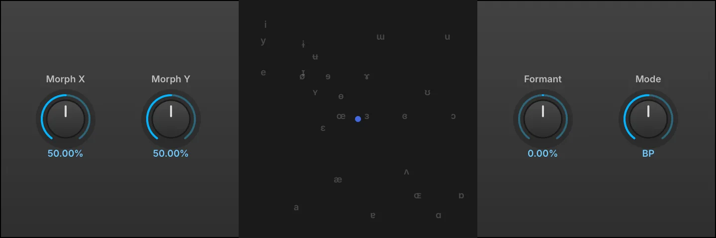
Infuse your sounds with a human touch. This formant filter uses precision resonant filters to mimic vowel shapes, allowing seamless blending between vowels for vocal-like textures and expressive effects.
Set with MORPH X (0–100 %) and MORPH Y (0–100 %) or click and drag the display to change the filter’s shape.
FORMANT (−100–100 %) controls how far the formant frequencies are shifted higher or lower.
MODE chooses the style of filter: low-pass (LP), band-pass (BP), or high-pass (HP).
Wahwah

Wahwah is a wah filter effect with full manual control over the wah amount, same as with an effect pedal.
WAH (0–100 %) sets the filter frequency, which is commonly modulated or controlled with a pedal or other MIDI controller.
DRIVE (0–100 %) sets the amount of overdrive applied.
MODEL chooses the pedal model, each with its own sweep range and resonance curve: Default, Cry, CryB, CryC, Vox, VoxM, or CryBassHigh.
MASTER (0–10) sets the output gain level.
Xpander Filter

A highly customizable multi-mode filter with 37 shapes, vintage and modern algorithms, built-in saturation and oversampling.
The number indicates the order of the filter (e.g. LP1 is a low-pass filter with a 6 dB/octave slope).
MODE sets the filter shape. Click the image to choose between 37 different options or use the left/right arrows to scroll through them.
Filter types include: LP - low-pass, HP - high-pass, BP - band-pass, AP - all pass, PK - peak filter, T - twin filter.
KEY TRACKING (0–100 %) changes how the cutoff frequency is adjusted relative to the note played. ALGORITHM allows you to choose between two modes: MODE I emulates a classic constant-Q filter solver, MODE II is a modern zero-delay filter solver. 2X enables oversampling for the filter and provides the cleanest results when active.
Overdrive
TYPE sets the style of overdrive used: Soft Saturation, Hard Clip, or Linear.
AMOUNT (−20–20 dB) sets the amount of overdrive used.
Filter
CUTOFF (20–20,000 Hz) sets the frequency for the filter; the note name of the corresponding frequency is also displayed (e.g. 2.00 kHz (B5)). RESONANCE (0–100 %) adjusts how much emphasis is given to the cutoff frequency. THICKNESS (0–100 %) overdrives the filter at lower frequencies to compensate for DC gain drop (e.g. crank it when you want more OOMPH than SIZZLE).
Equalizer
3 Band Shelf
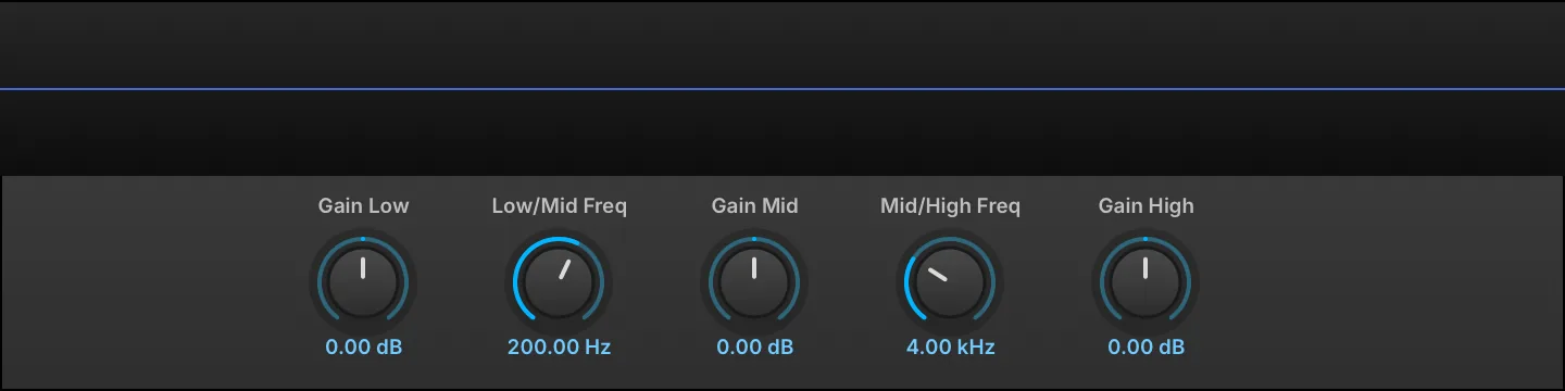
The 3 Band Shelf has Low, Mid, and High bands. The Mid band is a bell curve, while the Low and High bands are shelves.
The crossover points between the bands are set with the LOW/MID FREQ (20–1,000 Hz) and MID/HIGH FREQ (2,000–20,000 Hz) controls.
Each of the three bands has a GAIN (−24–24 dB) control for boosting or cutting its frequency.
Big Pi Tone

An emulation of the tone circuit in a popular fuzzbox guitar pedal.
At zero a low-pass filter is applied, at 10.00 a high-pass filter is applied, and the interim values are a blend of the two.
The blended result is similar to a shelving filter with a notch in the middle.
TONE (0–10) adjusts the amount and type of filter applied.
GAIN (0–10 dB) adjusts output level.
Convolver
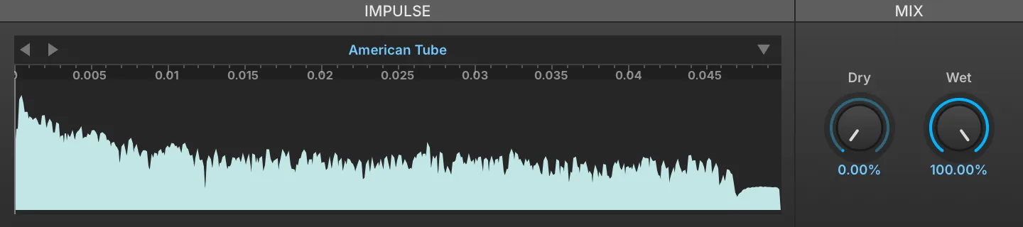
Convolver is a simple convolution processor, ideally suited for emulating EQs, cabinets, and so on. For reverb, the IReverb effect is recommended; see: Effects › Reverb › IReverb.
To load an IMPULSE RESPONSE, drag and drop an audio file to the sample area.
Mix
DRY (0–100 %) and WET (0–100 %) knobs set the balance between the dry (unaffected) and wet (affected) signal sent to the module’s output.
Impulse Files
To save the currently loaded impulse, use the Preset File menu and choose SAVE IMPULSE to save the current file or SAVE IMPULSE AS to save as a new file.
NORMALIZE POWER, enabled by default, scales each impulse response as it is loaded so that swapping impulses does not change the output level; it is reachable from the module’s parameter list rather than the front panel.
Digital EQ
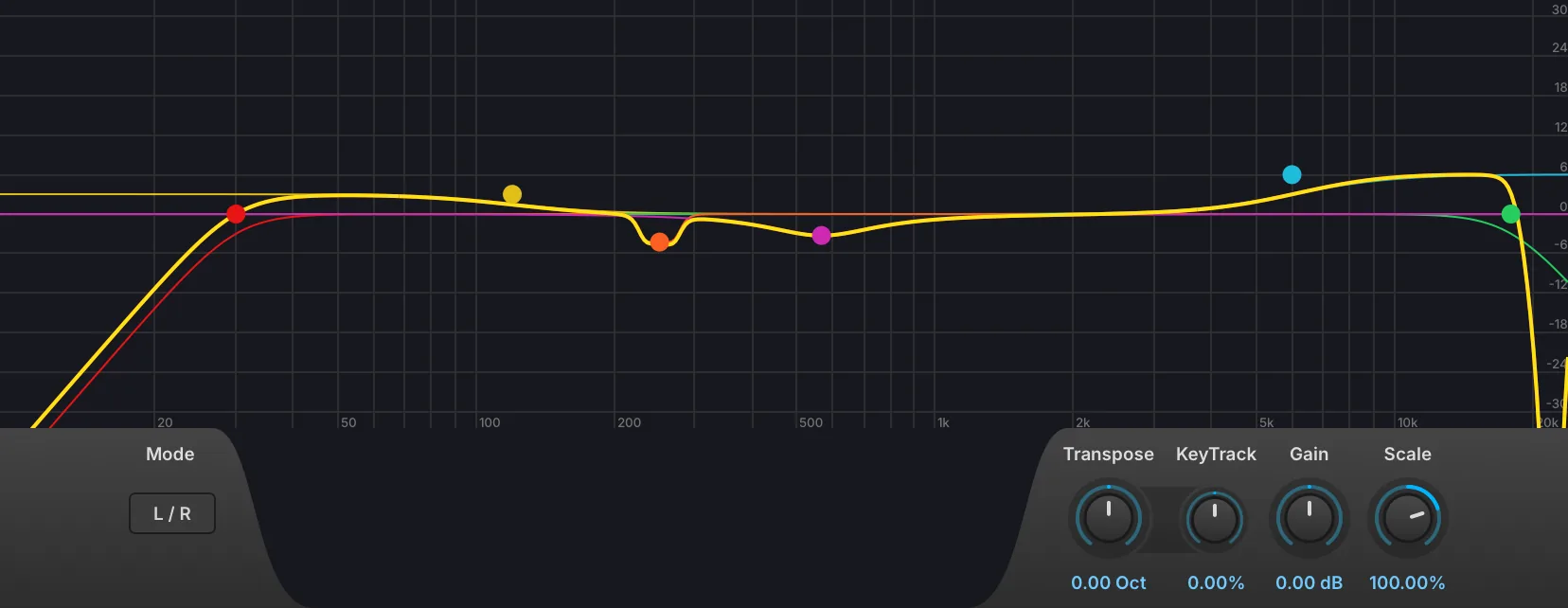
Digital EQ is a parametric EQ with up to 16 bands, variable filter shapes, L/R and M/S modes, interactive graphic display, transpose and key tracking.
The 16 bands each offer control of:
-
Bypass (power) button
-
Band selector
-
Channel selector: applies the band to both channels (All), or to the left or right channel only; in M/S mode, to the middle or side signal only.
-
EQ mode to choose the shape of the band: low-pass, high-pass, band-pass, notch, low-shelf, high-shelf and peak.
-
Slope sets the filter slope of the band: 6, 12, 18, 24, 36, 48, 72 or 96 dB/oct.
-
Frequency sets the frequency of the band.
-
Q adjusts the filter resonance.
-
Gain adjusts the band level in dB.
-
Bandwidth changes the frequency width.
-
Split (scissors) button copies the band into the next unused band and assigns one copy to the left channel and the other to the right.
-
Remove (X) button disables the band and takes it off the display.
In addition to the knobs and toggle switches, the bands can also be edited graphically in the frequency graph:
-
Press and drag a point to adjust its frequency by dragging right/left, or its gain by dragging up/down.
-
Press and drag a band’s color bars to adjust Q.
-
Right-click a point to enable/disable the band.
-
Double-click a point to return it to its default value.
-
When a band is selected, an information box is displayed in the upper left. As the band is adjusted, its Gain, Frequency, and Q values update in real time.
To view a larger graph, drag the bottom edge of the module to resize it.
MODE sets the stereo mode to L/R or M/S.
GAIN (−30–30 dB) adjusts overall output level.
-
SCALE (−200–200 %) scales the gain of every band and the overall Gain; negative values invert the boosts and cuts.
-
TRANSPOSE (−10 to 10 octaves) shifts the frequency of every band.
KEY TRACKING (−100–100 %) changes how the cutoff frequency is adjusted relative to the note played.
Harmonic Resonators
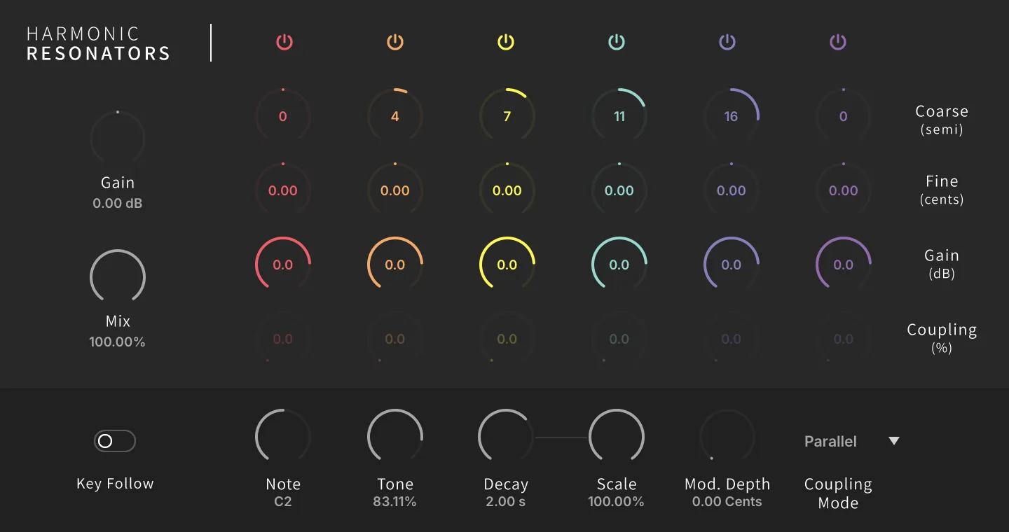
The effect version of our resonator bank, offering 6 channels with coarse and fine tune, gain, coupling, key follow, and more.
The 6 bands each offer control of:
-
Bypass (power) button
-
Coarse to set the filter frequency in semitones.
-
Fine to fine-tune the filter frequency in cents.
-
Gain adjusts the band level in dB.
-
Coupling (0–100 %) to set the coupling amount; only active in Reflect and RotCirc (aka Circular Rotation) modes.
GAIN (−20–20 dB) adjusts overall output level. MIX (0–100 %) sets the dry and wet signal balance.
KEY FOLLOW to enable key tracking mode, NOTE sets the base note for the filters when the Key Follow switch is off.
TONE (0–100 %) adjusts the high frequency damping of each harmonic resonator, sweeping the damping corner from 440 Hz at 0 % (darkest, most damped) up to 20 kHz at 100 % (brightest, undamped).
DECAY (20–20,000 ms) sets the filter decays of all bands. SCALE (0–100 %) evens out the band decays: at 0 % a band tuned an octave up rings half as long as one at the played note, at 100 % every band rings for the full Decay time whatever its tuning. MOD. DEPTH (0–20 cents) sets the filter modulation depth in cents.
COUPLING MODE sets the relationship between the filter bands:
-
Parallel mode: processing all bands in parallel (or independently).
-
Reflect mode: a weighted sum of each resonator’s energy is fed back into all the others.
-
RotCirc mode: rotates a small fraction of energy from each band to the next (circularly).
Passive EQ
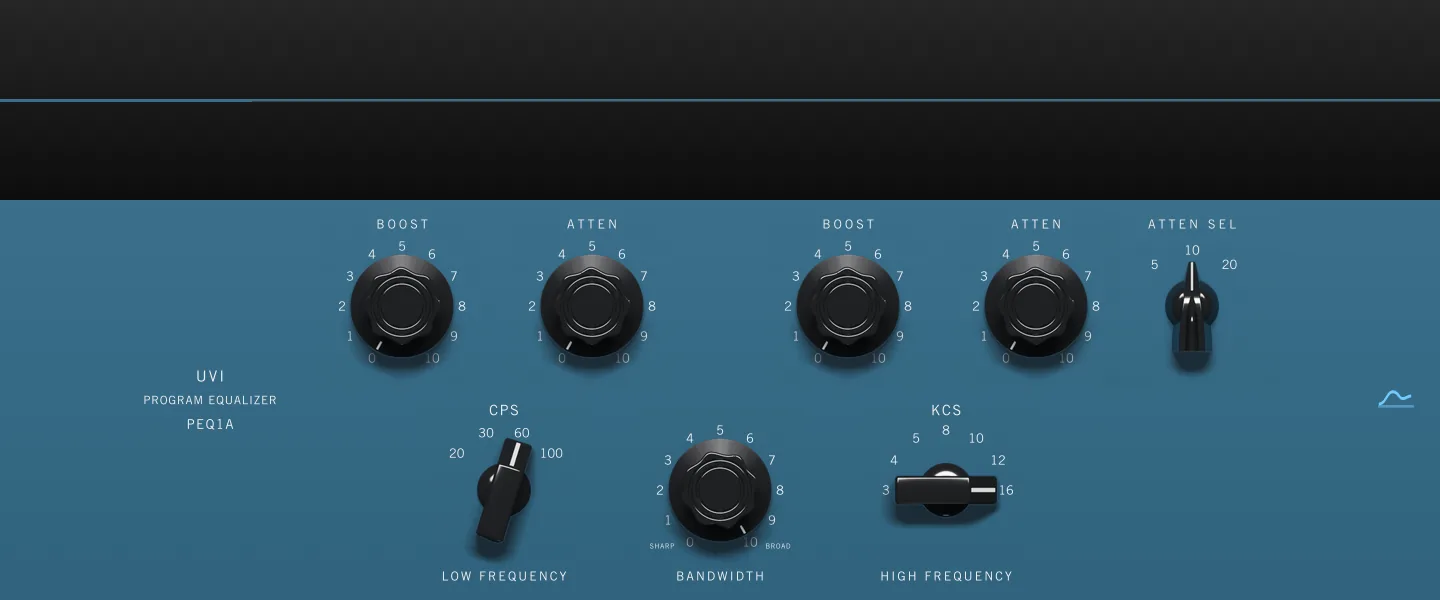
Passive EQ is a model of a passive tube program equalizer, solved from the state space of the original circuit rather than assembled from a chain of digital filters. Its low band boost and attenuation run through separate networks and land on deliberately offset curves, so raising and cutting the same frequency at once does not cancel out. The front panel carries no module name, only the PROGRAM EQUALIZER legend of the hardware it follows.
LOW BOOST (0–100 %) and LOW ATTENUATION (0–100 %) set the amount of boost and of cut applied at the low frequency. The cut is centered above the boost, so applying both leaves a lifted bottom with a broad dip just above it — the trick this design is known for, which thickens a sound while keeping it clear.
LOW FREQUENCY (20, 30, 60, 100 Hz) selects the frequency the low boost and the low attenuation act on; the panel marks it in CPS.
HIGH BOOST (0–100 %) sets the amount of boost applied at the high frequency, and BANDWIDTH (0–100 %) sets the width of that peak, sharp at 0 % and broad at 100 %.
HIGH FREQUENCY (3, 4, 5, 8, 10, 12, 16 kHz) selects the frequency of the high boost peak; the panel marks it in KCS.
HIGH ATTENUATION (0–100 %) sets the amount of cut applied by the high shelf, and HIGH ATTEN. SEL. (5, 10, 20 kHz) selects the frequency it acts on. The boost and the shelf are independent, so a peak can be lifted underneath a top end that is being pulled down.
The CURVE button in the upper right of the panel shows or hides the response display above it, which plots the resulting magnitude from 20 Hz to 20 kHz on a ±20 dB scale.
Tilt

With negative values, the low shelf is boosted and the high shelf is cut; the opposite occurs with positive values.
The Tilt module has two shelf bands, a low shelf and a high shelf, which are applied inversely.
The TILT (−6–6 dB) control sets the amount of gain applied to each band.
CUTOFF (20–20,000 Hz) sets the frequency for the EQ; the note name corresponding to the frequency is also displayed, for example, 2.00 KHZ (B5).
Tone Stack

Tone Stack emulates the tone controls found on many common amplifier heads.
MODEL chooses the style of amplifier head.
BASS (0–100 %), MID (0–100 %), and TREBLE (0–100 %) controls set the relative levels for each tone band.
GAIN (0–100 %) sets an output boost applied after the tone stack, rising from unity at 0 % to +20 dB at 100 %; it only ever adds level, it never attenuates.
Amp & Stereo
Autopan

Autopan varies stereo panning with an LFO.
SPEED (0–20 Hz) sets how quickly one auto-pan cycle is completed, in Hz or bars/beats (if tempo-synced).
DEPTH (0–100 %) sets how far across the stereo field the auto-pan will cover, with 100 percent covering the full distance from hard left to hard right.
MODE chooses the pan law used by the auto-pan cycle: Linear, Equal-power, Balance, or Rotate.
Gain

Gain is a simple level adjustment module, used to boost or cut the signal level.
VOLUME sets the amount of boost or cut, from +12 dB to -∞
Gain Matrix
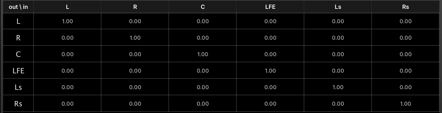
Gain Matrix sets the gain level and phase of each channel. This allows for simple per-channel gain adjustments, or for specialized gain/phase transformations. Factory presets provide some common transformations, such as decoding mid-side to stereo.
The INPUT channels are listed down the side, and the OUTPUT channels are listed across the top. Each in/out relationship can be edited by typing in a new value or clicking and dragging the value:
-
At 1.00, the signal is passed through at full strength and its original phase.
-
At 0.00, output is silenced for that channel.
-
At -1.00, the output is passed through at full strength but with the opposite phase.
Gain Matrix also supports multi-channel configurations, such as quad, 5.1, 7.1, and others.
Tremolo

Tremolo varies amplitude with an LFO.
FREQ (0–20 Hz) sets how quickly the LFO cycle is completed, in Hz or bars/beats (if tempo-synced).
DEPTH (0–100 %) sets how far across the gain range the cycle will cover, with 100 percent covering the full distance from -∞ to 0 dBFS.
UVI Wide

UVI Wide is a stereo width enhancer with a high-shelf filter.
WIDTH (−100–100 %) adjusts the stereo spread of the module’s output. At zero, the stereo image of the input signal is unaffected. Positive values increase the stereo spread and negative values reduce it, down to a mono signal at -100%.
DELAY (−15–15 ms) sets the amount of delay applied to one channel to help create a wider stereo image.
Extra Width
The Extra Width controls provide additional frequency control by way of a high-shelf EQ applied to the side channel of the module’s M/S decomposition, so it emphasizes (or tames) the stereo difference signal only.
EXTRA WIDTH FREQ (2,000–20,000 Hz) sets the EQ frequency.
EXTRA WIDTH GAIN (−15–15 dB) sets the EQ gain adjustment (+/-).
Drive & Distortion
Analog Crunch

Analog Crunch is inspired by overdrive/distortion effect pedals commonly used with electric guitars.
INPUT GAIN (−30–20 dB) sets the gain adjustment into the module, before any distortion is applied.
OVERDRIVE (0–10) and TRASH (0–100 %) set the amount and character of the distortion.
The SHAPING DISPLAY plots the module’s output waveform (blue) against a reference sine wave input (purple), so the effect of the current settings can be seen directly.
Oversampling
Sets the AMOUNT of oversampling applied (if any), from 2x to 16x.
Output
MIX (0–100 %) sets the balance between the clean and overdriven signals. GAIN (−40–10 dB) sets the final, post-distortion gain adjustment.
Diode Clipper

Diode Clipper is a circuit-modeled diode clipping stage similar to those found in many overdrive stomp boxes.
The circuit of Diode Clipper includes a passive nonlinear, dynamic-driven HP/LP filter that exhibits effects like hysteresis when saturated.
DRIVE (0–30 dB) controls the overall effect intensity.
ASYMMETRY (0–100 %) shifts the saturation symmetry between the two diodes, affecting the even/odd harmonic ratio.
The SHAPING DISPLAY plots the module’s output waveform (blue) against a reference sine wave input (purple), so the effect of the current settings can be seen directly.
Contour
TONE (100–20,000 Hz) sets the frequency of the LP filter. HIGH PASS (1–20,000 Hz) controls the HP filter frequency.
Output
GAIN (−40–10 dB) sets the final, post-distortion gain adjustment.
Drive

Drive offers a straight-ahead drive/distortion, with three different flavors of distortion.
As oversampling is processor intensive, it’s recommended to apply oversampling as little as is necessary to reduce unwanted aliasing. Often, no oversampling will be needed.
MODE sets the style of drive (Analog, Mild, or Strong).
AMOUNT (0–100 %) sets the amount of drive.
Use OVERSAMPLING to set the amount of oversampling applied (if any), from 2x to 16x.
Exciter

Exciter is a classic exciter effect, adding brightness and saturation.
INPUT GAIN (−30–20 dB) sets the gain adjustment into the module, before any distortion is applied.
AMOUNT (0–15) chooses the amount of excitation applied.
The SHAPING DISPLAY plots the module’s output waveform (blue) against a reference sine wave input (purple), so the effect of the current settings can be seen directly.
Mode
MODE sets the style of exciter, using common characteristics of Tape or Tube exciters.
Use OVERSAMPLING to set the amount of oversampling applied (if any), from 2x to 16x.
Output
MIX (0–100 %) sets how much of the excited signal is blended into the output. In Tape mode this is a crossfade against the clean signal; in Tube mode the clean signal is never attenuated, so the excitation is added on top of it.
GAIN (−40–10 dB) sets the final, post-distortion gain adjustment.
Fuzz

Fuzz is inspired by classic fuzz guitar and bass effect pedals.
INPUT GAIN (−30–20 dB) sets the gain adjustment into the module, before any fuzz is applied.
OVERDRIVE (0–10) and TRASH (0–100 %) set the amount and character of the fuzz.
The SHAPING DISPLAY plots the module’s output waveform (blue) against a reference sine wave input (purple), so the effect of the current settings can be seen directly.
Oversampling
Sets the AMOUNT of oversampling applied (if any), from 2x to 16x.
Output
MIX (0–100 %) sets the balance between the clean and fuzzed signals.
GAIN (−40–10 dB) sets the final, post-distortion gain adjustment.
Guitar Boxes

Guitar Boxes emulates a guitar cabinet, with multiple cabinet models and mic types.
MIX (0–100 %) sets the balance between the original and amplified signals.
SEPARATION (−30–30 ms) offsets one channel against the other to emulate the distance from cabinet to microphone: positive values delay the left channel, negative values the right. It has no effect on a mono signal.
SPREAD sets the amount of stereo spread, from zero percent (mono) to 100 percent (full stereo).
CABINET chooses the cabinet, from well-known models to general device types to unusual FX simulations. It is picked from the icon at the left of the panel, and the display beside it draws the frequency response of the cabinet and microphone together, from 20 Hz to 20 kHz.
MICROPHONE adjusts the characteristic of the microphone capturing the amplified signal, as a Dynamic, Condenser, or Ribbon mic. It has its own icon beside the cabinet.
Magnetic Bass Shaper

Abuse the saturating hysteretic behavior of famous inductors to shape and add punch to bass sounds while leaving high frequencies clean.
GAIN (−30–30 dB) sets the gain adjustment into the module.
DRIVE (0–30 dB) sets the amount of the drive applied to the signal.
MODEL selects the magnetization model of the coil, Model C or Model I, each with its own hysteresis behavior. INDUCTOR selects the coil itself, Fasel Red or Fasel Yellow, each measured to give a unique distortion profile.
CUTOFF (1–500 Hz) sets the frequency cutoff of the inductor circuit.
GAIN (−30–30 dB) sets the output gain adjustment.
The SHAPING DISPLAY plots the module’s output waveform (blue) against a reference sine wave input (purple), so the effect of the current settings can be seen directly.
Overdrive

Overdrive emulates overdrive distortion commonly used on guitars.
INPUT GAIN (−30–20 dB) sets the gain adjustment into the module, before any distortion is applied.
OVERDRIVE (0–10) sets the gain driving the overdrive stage, and TRASH (0–100 %) brings in the soft saturation that gives it its character. With TRASH at zero the drive path stays clean, however high OVERDRIVE is set.
The SHAPING DISPLAY plots the module’s output waveform (blue) against a reference sine wave input (purple), so the effect of the current settings can be seen directly.
Oversampling
Sets the AMOUNT of oversampling applied (if any), from 2x to 16x.
Output
MIX (0–100 %) sets the balance between the clean and overdriven signals.
GAIN (−40–10 dB) sets the final, post-distortion gain adjustment.
TS Overdrive

Drive-stage emulation of the Tube Screamer overdrive pedal with custom mods.
INPUT VOLTAGE (0.1–2) sets the input voltage adjustment into the module, before any distortion is applied.
DRIVE (0–100 %) and ASYMMETRY (0–100 %) set the amount and character of the overdrive.
The SHAPING DISPLAY plots the module’s output waveform (blue) against a reference sine wave input (purple), so the effect of the current settings can be seen directly.
Bandwidth
LOW FREQ (100–2,000 Hz) and HIGH FREQ (10,000–100,000 Hz) set the corners of the band the drive stage boosts and clips. High Freq is the corner at minimum Drive; raising Drive lowers it by up to a factor of ten (1,000–10,000 Hz at full Drive), which is why its range extends past the audible band.
OUTPUT GAIN (0.1–10) sets the final, post-distortion gain.
Tube Amp
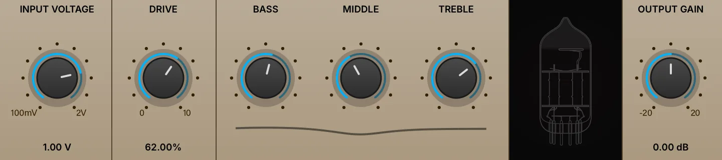
An exacting digital model of a British high-gain classic. By simulating the full circuit and vacuum tubes, Tube Amp delivers the authentic tone, grit, and dynamic response of legendary hardware.
INPUT VOLTAGE (0.1–2) sets the input voltage adjustment into the module, before any distortion is applied.
DRIVE (0–100 %) sets the amount of the overdrive.
BASS (0–100 %), MIDDLE (0–100 %) and TREBLE (0–100 %) adjust the low, mid and high frequencies of the amplification signal.
OUTPUT GAIN (0.1–10) sets the final, post-distortion gain.
Wavefolder
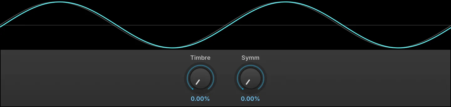
Wavefolder is the folding circuit of the West Folder oscillator on its own, as an effect: instead of clipping a signal that is driven too hard, it folds the peaks back on themselves, adding harmonics that move with the input level rather than simply squaring it off. It works on anything, but is at its most characteristic on sustained tones and simple waveforms, where each new fold is audible as it appears.
The display draws a sine run through the folder at the current settings, over the same sine undistorted. It is normalized to its own peak, so what the controls change is the shape rather than the level.
TIMBRE (0–100 %) sets the gain into the folding circuit, from half the level of the input up to ten times it. The harder it drives, the more times the wave folds back on itself, so it is the main control over how much harmonic content is added.
SYMM (0–100 %) offsets the signal before it reaches the folder, so it no longer folds symmetrically about zero. This brings in even harmonics, for a hollower, reedier tone.
Wave Shaper
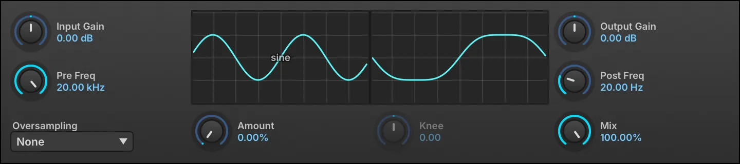
Wave Shaper distorts the input signal by transforming the shape of the waveform, which often results in heavily distorted sounds.
INPUT GAIN (−40–40 dB) sets the gain adjustment into the module, and PRE FREQ (20–22,000 Hz) sets the frequency of a low-pass filter applied before any waveshaping.
Choose the WAVE SHAPE by clicking the waveform and selecting a wave from the menu, then use AMOUNT (0–100 %) and KNEE (−10 to 10) to adjust characteristics of the wave shape. (Not available in some shapes).
AMOUNT is active for the sine, Fold-back, tanh, atan, HyperSine, Asym and Exp shapes, and KNEE for tanh, atan, Damped sat and Exp. Both controls are grayed out for the shapes that do not use them.
Use OVERSAMPLING to set the amount of oversampling applied (if any), from 2x to 16x. As oversampling is processor intensive, it’s recommended to apply oversampling as little as is necessary to reduce unwanted aliasing. Often, no oversampling will be needed.
POST FREQ (2–20,000 Hz) sets the frequency of a high-pass filter applied after waveshaping. OUTPUT GAIN (−40–40 dB) sets the gain adjustment, after waveshaping is applied.
MIX (0–100 %) sets the balance between the dry and shaped signals.
Dynamics
3-Band Compressor
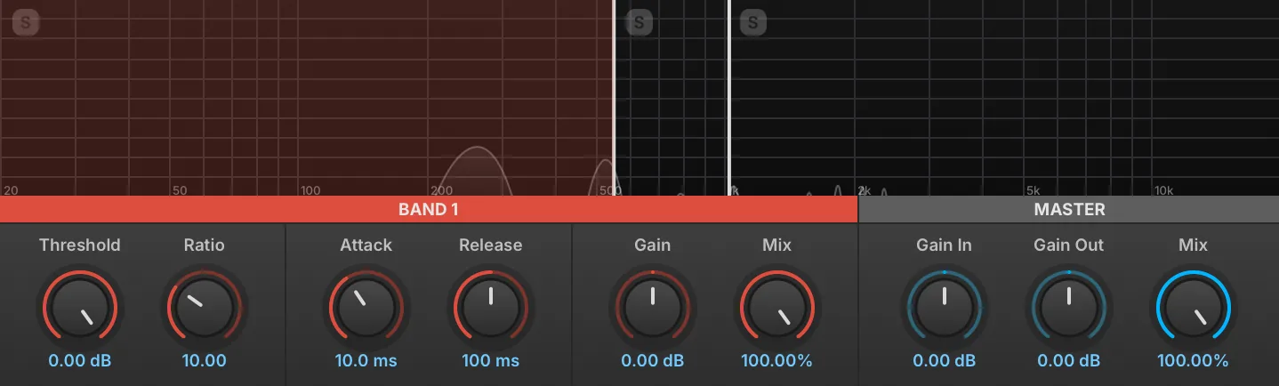
The 3-Band Compressor is a multiband version of the compressor, with adjustable crossover frequencies.
The 3-Band Compressor has Low, Mid, and High bands.
To select a band to edit, click in the corresponding area of the display - the parameters for that band will be displayed below in a matching color.
To change the crossover frequency between bands, click-drag the border line between them.
To solo a band, click the [S] button in the upper-left of the band display.
Band 1–3 Each of the three bands has standard compressor controls: THRESHOLD (−130–0 dB), RATIO (1–30), ATTACK (0–500 ms), RELEASE (0–5,000 ms), GAIN (−30–30 dB) and MIX (0–100 %). For more information on compressor settings, see: Effects › Dynamics › Compressor Expander.
Each band also carries an AUTO-MAKEUP parameter, which adds an automatic compensation for that band’s gain reduction on top of its Gain setting. It is off by default and has no switch on the panel; reach it from the parameter list or as a modulation target.
Master GAIN IN (−30–30 dB) sets the global input gain. GAIN OUT (−30–30 dB) sets the global output gain. MIX (0–100 %) sets the dry and wet signal balance.
3 Band Limiter
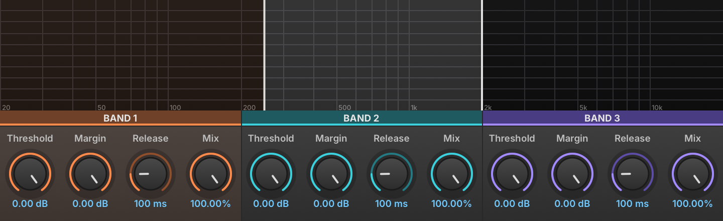
The 3 Band Limiter is a multiband version of the Studio Limiter, with adjustable crossover frequencies.
The 3 Band Limiter has Low, Mid, and High bands. The crossover points between the bands are set with the LOW/MID FREQ (20–20,000 Hz) and MID/HIGH FREQ (20–20,000 Hz) controls.
Each of the three bands has standard limiter controls: THRESHOLD (−20–0 dB), MARGIN (−5–0 dB), and RELEASE (10–500 ms). For more information on limiter settings, see: Effects › Dynamics › Studio Limiter.
Compressor Expander
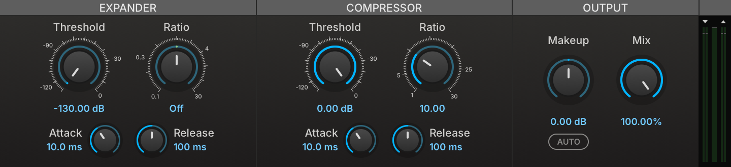
Compressor Expander is a dual dynamics processor — the compressor tames signal peaks over a chosen threshold, and the expander attenuates the signal below a second, independent threshold.
Both the compressor and expander have Threshold, Ratio, Attack, and Release controls. THRESHOLD (−130–0 dB) sets the level at which the compressor or expander will be applied. RATIO sets the ratio between input gain and output gain. The expander RATIO (0.1–30) expands downward above 1, lifts low levels below 1, and does nothing at 1. ATTACK (0–500 ms) and RELEASE (0–5,000 ms) set the speed at which the compressor or expander begins or stops processing the signal after it has crossed the threshold.
MAKEUP GAIN (−30–30 dB) applies a manual gain adjustment to compensate for the gain reduction of the compressor. AUTO MAKEUP adds a further compensation derived from the compressor’s threshold and ratio; it is applied on top of Makeup Gain, not in place of it.
MIX (0–100 %) sets the balance between the dry (unaffected) and wet (affected) signal sent to the module’s output.
Lastly, the INPUT METER on the left side of the module displays the level of the input signal, and the GAIN REDUCTION METER on the right side of the module displays the amount of gain reduction applied. Note that the righthand meter is not an output meter.
FET Compressor

FET Compressor is a model of the classic FET limiting amplifier, solved from its circuit so that the ratio, the sidechain gain and the output line amp all interact as they do in the hardware. It has no threshold control: the ratio buttons are what set the shape of the curve, and Input Gain is what moves the knee along it, as on the original. Its attack and release are numbered dials rather than times.
IN (−20–20 dB) sets the gain applied to both the signal and the detector, so it moves the operating point on the curve as well as the level. OUT (−40–40 dB) is the makeup gain applied at the output.
RATIO is a column of buttons reading 4:1, 8:1, 12:1 and 20:1, the machine’s own markings rather than measured slopes. Each one sets the sidechain gain and the transistor’s bias together, which is what the hardware’s ratio switch does.
ALL presses all four at once, as the original lets you jam them: the ladder’s sections short together and the sidechain gain rises without the bias following, so it reduces more gain than any of the four buttons, even 4:1, and lands off the path the four buttons travel. Ratio goes inert while it is engaged.
CONT replaces the column of buttons with a continuous control over the same 4:1 to 20:1 range, for settings between the machine’s four.
ATTACK (1–7) and RELEASE (1–7) are the panel’s numbered dials, 1 the slowest setting and 7 the fastest, each step being the same ratio of time rather than the same number of milliseconds. The circuit’s slow reservoir keeps the release program dependent, so it runs longer after a long passage of compression, which is why the dial is marked rather than timed.
DRIVE (−6–40 dB) drives the output line amp. It is level-compensated afterwards, so it changes the tone of the output stage rather than its loudness.
MIX (0–100 %) sets the balance between the dry (unaffected) and wet (affected) signal sent to the module’s output.
The VU METER reads either gain reduction or output level, selected by the GR and OUT buttons below it.
The ANALYSIS button unfolds three displays below the panel. The static curve plots output against input for a held sine, the diagonal being unity and the grid 10 dB; Ratio, All and In all move it. The drive display shows a full-scale sine through the output line amp at the current Drive setting, against the same sine undistorted. The third scrolls the input and output levels over time.
Feedback Compressor
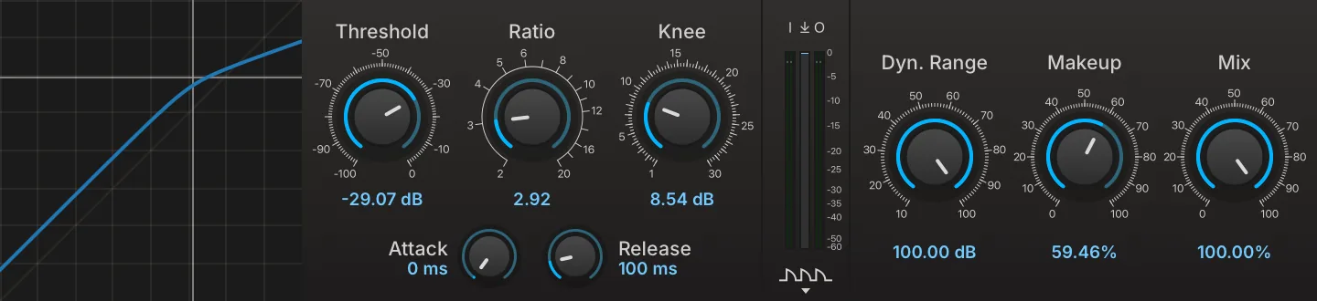
Feedback Compressor is a modern take on vintage compression. By focusing solely on feedback designs we wanted to retain the particular behavior and characteristics of old compressors, such as time constants that depend on the ratio and signal, and a limited amount of gain reduction, but at the same time offer full parametric control over the transfer function, soft-knee, makeup gain, and parallel compression.
THRESHOLD (−100–0 dB) sets the output level above which the compressor starts reducing gain. RATIO (2–20) sets the ratio between input gain and output gain. KNEE (1–30 dB) adjusts the smoothness of the compression knee. ATTACK (0–100 ms) and RELEASE (50–1,000 ms) set the speed at which the compressor begins or stops processing the signal after it has crossed the threshold; the attack time also scales with the ratio, so a given attack setting engages more gradually at higher ratios.
The I↓O METER displays the level of the input, gain reduction and output signal, and the switch at the bottom of the meters toggles the TIMELINE to display the gain reduction over time.
INPUT GAIN (−40–40 dB) sets the gain applied to the signal before compression, and OUTPUT GAIN (−40–40 dB) sets the gain applied at the very output, after compression and mix.
DYN. RANGE (10–100 dB) caps the maximum gain reduction the compressor can apply, however far the signal runs above the threshold.
MAKEUP GAIN (0–100 %) sets how much of the automatic gain compensation is applied, from none at 0 % to full compensation at 100 %. The amount compensated is computed from the threshold, ratio and dynamic range, so it follows the compression settings rather than being dialed in decibels.
MIX (0–100 %) sets the balance between the dry (unaffected) and wet (affected) signal sent to the module’s output.
Feedforward Compressor
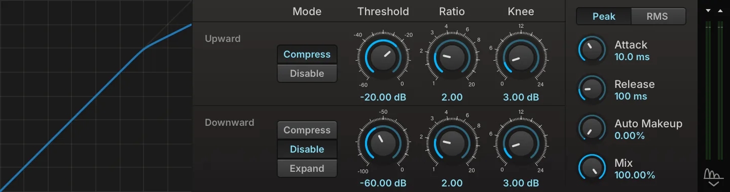
Feedforward Compressor derives its gain from the incoming signal, measured before any processing, so its response depends only on what enters the effect and not on what it has already done to it. Its transfer curve is built from two independent segments, one acting above an upward threshold and one below a downward threshold, each with its own ratio and knee, so a single instance can flatten peaks, lift a quiet body, or push a tail further down. A shared envelope, peak or RMS detection, continuous auto makeup and a dry/wet mix are common to both.
The STATIC CURVE on the left plots output against input for the current settings, with a marker following the incoming level.
UPWARD acts on everything above its threshold, and is switched between DISABLE and COMPRESS. Its THRESHOLD (−60–0 dB) sets the detected level at which the segment starts acting, RATIO (1–20) sets the input-to-output ratio above it, and KNEE (0–24 dB) sets the width of the transition around it, 0 dB giving a hard corner.
DOWNWARD acts on everything below its threshold, and is switched between DISABLE, COMPRESS, which lifts quiet levels, and EXPAND, which pushes them further down. Its THRESHOLD (−100–0 dB), RATIO (1–20) and KNEE (0–24 dB) work as they do on the upward segment, applied in the direction the mode selects.
The GLOBAL section applies to both segments. ATTACK (0–500 ms) and RELEASE (0–5,000 ms) set the time the detector takes to follow a rise and a fall of the input level. PEAK / RMS selects whether that level is measured as a peak or as an RMS average, peak reacting to transients and RMS to the body of the signal.
AUTO MAKEUP (0–100 %) sets how much automatic gain compensation is applied, from none at 0 % to bringing the loudest output back to 0 dB at 100 %.
MIX (0–100 %) sets the balance between the dry (unaffected) and wet (affected) signal sent to the module’s output.
The two meters in the well at the right edge of the panel show the input and output levels, marked with a downward and an upward arrow for the two buses, and the button below them unfolds a scrolling history of both under the panel.
Gate

Gate is a traditional gate, silencing signals below a chosen threshold.
THRESHOLD (0–1) sets the level at which the gate will be applied.
ATTACK (0.0001–0.1 s) and RELEASE (0.01–1 s) set the speed at which the gate begins or stops processing the signal after it has crossed the threshold.
Maximizer
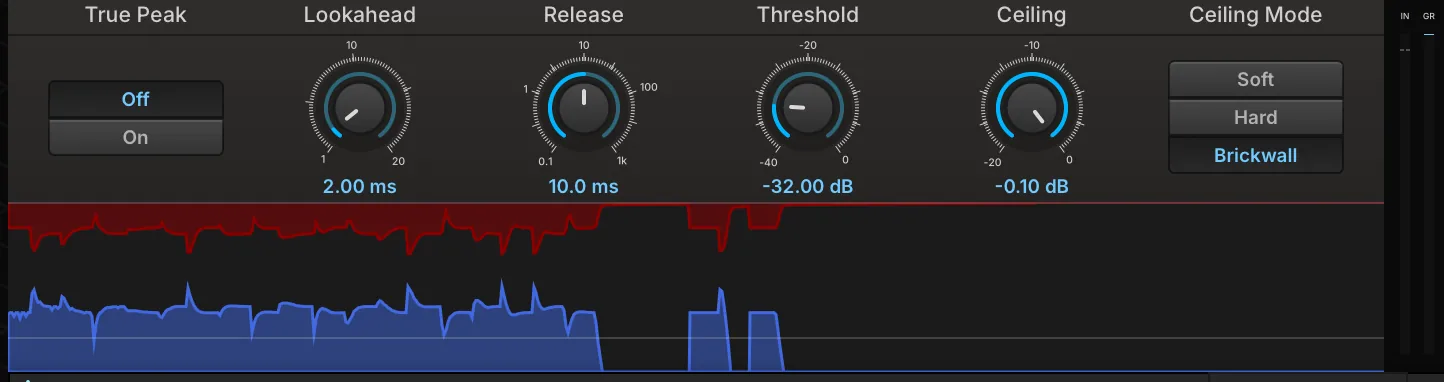
Maximizer is a lookahead limiter with a graphical timeline to visualize the dynamic range of the input and output.
THRESHOLD (−40–0 dB) sets the level at which limiting will be applied, and CEILING (−20–0 dB) sets the maximum output level.
LOOKAHEAD (1–20 ms) sets the amount of time the module will look ahead at the input signal; longer lookahead times can achieve a better response for transients and other sudden changes in amplitude.
RELEASE (0.1–1,000 ms) sets the speed at which the limiter stops processing the signal after it has fallen below the threshold.
CEILING MODE is a column of buttons setting how the ceiling is held. Soft lets the Attack setting shape the envelope, so the ceiling is approached rather than guaranteed; Hard keeps that envelope and puts a clipper at the ceiling behind it; and Brickwall, the default, uses an instant attack so the envelope enforces the ceiling on its own.
ATTACK (0–20 ms, default 0 ms) is not on the panel; reach it from the parameter list. It sets the time the gain reduction takes to engage and is used by Soft and Hard only.
TRUE PEAK switches between Off, where the ceiling holds for sample peaks, and On, where it also holds for the inter-sample peaks found on a four-times oversampled sidechain.
The TIMELINE displays the input signal and gain reduction over time. The blue graph rises from the bottom of the timeline and indicates the amplitude of the input signal; the red graph grows downward from the top of the timeline and indicates gain reduction.
The INPUT METER on the left side of the module displays the level of the input signal, and the GAIN REDUCTION METER on the right side of the module displays the amount of gain reduction applied. Note that the right-hand meter is not an output meter.
Opal
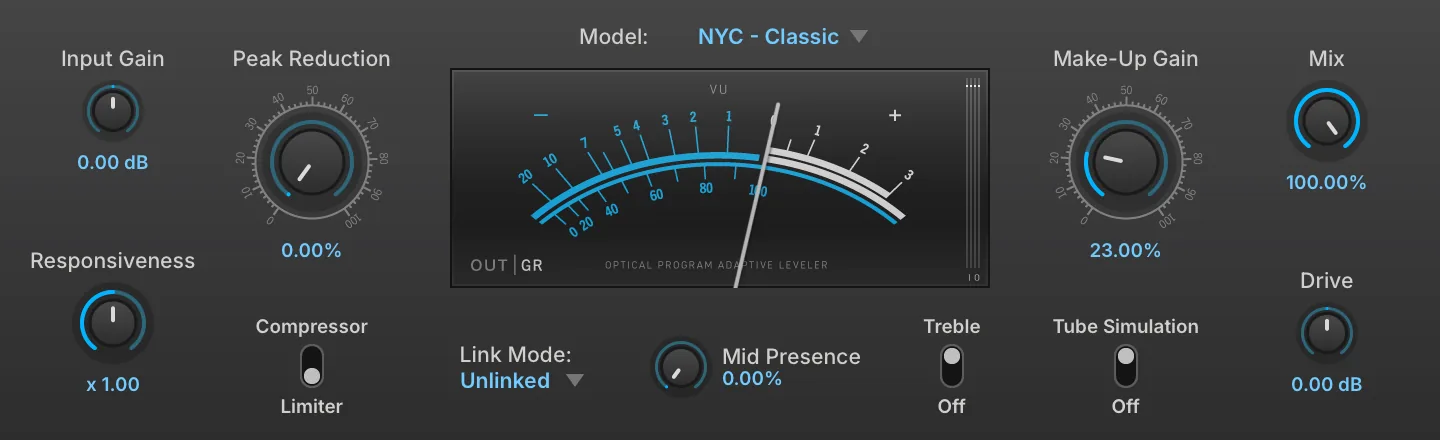
Based on a classic hardware optical compressor, Opal provides impressive realism thanks to deep physical modeling. 7 uniquely modeled flavors are available offering a range of useful characters.
MODEL chooses a model among seven emulations of real studio leveling amplifiers (optical compressors), each with its own character (dynamic range and response time).
INPUT GAIN (−20–20 dB) controls the gain applied to the signal before compression.
PEAK REDUCTION controls the detection threshold. Maximal threshold at 0% peak reduction, minimal threshold at 100 % peak reduction.
RESPONSIVENESS (0.1–10) multiplies the response time (attack and release, jointly). The response time is still program-dependent but can be set shorter or longer for a given input.
COMPRESSOR/LIMITER switches the operation mode between compressor and limiter.
LINK MODE click to show the drop-down menu to set the stereo link mode based on Left, Right, Mono (LR sum), Max ch (the louder of the Left or Right channels) or Unlinked (link off).
MID PRESENCE (0–100 %) controls the sidechain filter frequency response, this corresponds to the original R37 “emphasis” control.
TREBLE enables the treble boost of the Make-Up Gain stage. It acts on the non-tube path only, so the control is unavailable while TUBE SIMULATION is active.
VU METER indicates output or gain reduction level by OUT|GR toggle, the IO METER displays the level of the input and output signal.
MAKE-UP GAIN (0–100 %) applies a manual gain adjustment to compensate for the gain reduction of the compressor.
TUBE SIMULATION turns on or off the full physical modeling tube simulation for Make Up Gain. More CPU intensive when switched on.
MIX (0–100 %) sets the balance between the dry (unaffected) and wet (affected) signal sent to the module’s output.
DRIVE (−40–40 dB) adjusts the gain applied to the signal fed into Make Up Gain when the Tube Simulation is active.
EXTERNAL drives the detection from the external sidechain input instead of the signal being processed.
Studio Limiter

The Studio Limiter is a high-quality limiter, suited for individual parts or for full stereo mixes.
THRESHOLD (−20–0 dB) sets the level at which limiting will be applied.
MARGIN (−5–0 dB) sets the maximum output level, which can also be thought of as the margin between the maximum signal output by the limiter and zero dBFS.
RELEASE (10–500 ms) sets the speed at which the limiter stops processing the signal after it has fallen below the threshold.
MIX (0–100 %) sets the balance between the dry (unaffected) and wet (affected) signal sent to the module’s output.
Pitch
Harmonizer
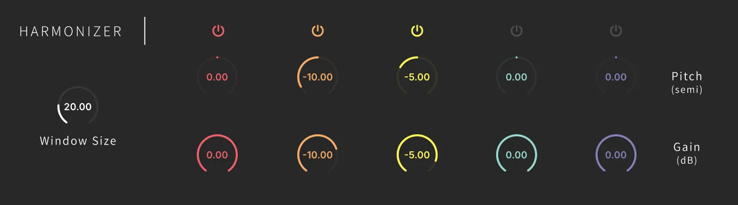
Harmonizer is a simple and effective effect to create up to 5-voice harmony. Ideal for sounds that have a dominant monophonic component but are not required to be exactly periodic.
WINDOW SIZE (10–60 ms) sets the size of the window (a processing unit applied to the signal for pitch-shifting).
POWER enables the voice.
PITCH sets the pitch shift in semitones (+/-12).
GAIN (−40–0 dB) adjusts the voice gain.
Shifter

Shifter is a simple and effective effect using the pitch-shifting engine, ideal for sounds that have a dominant monophonic component but are not required to be exactly periodic.
PITCH sets the pitch shift in semitones (+/-12), and FINE adjusts the pitch shift in cents (+/-100). Enable QUANTIZE to make a stepped pitch bend effect when controlling or modulating the pitch control in real time.
WINDOW SIZE (10–60 ms) sets the size of the window (a processing unit applied to the signal for pitch-shifting).
MIX (0–100 %) sets the balance between the dry (unaffected) and wet (affected) signal sent to the module’s output.
Analysis
Loudness Meter
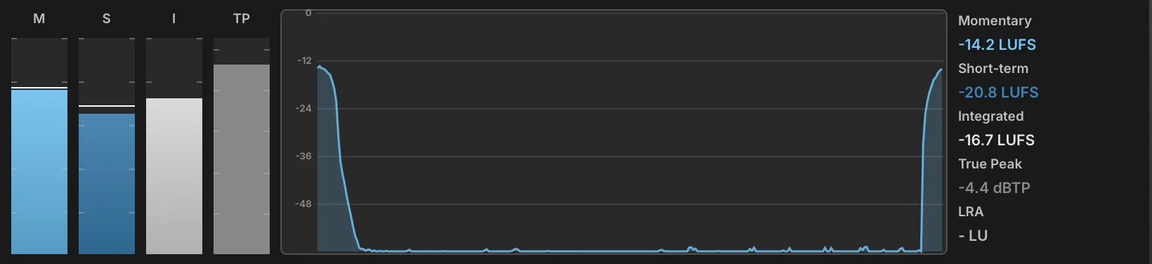
The Loudness Meter measures program loudness to the ITU-R BS.1770 and EBU R128 broadcast standards, showing momentary, short-term and integrated loudness alongside true peak and loudness range. It is the meter to reach for when a patch has to sit at a delivery target rather than simply avoid clipping, since none of those readings can be inferred from a peak meter. The module has no settings: everything on it is a reading.
Four bars fill the left of the display, labeled above their scales. M is the momentary loudness, measured over a 400 ms window, and S the short-term loudness, measured over 3 s; both carry a horizontal line marking the highest value reached since the last reset. I is the integrated loudness, gated as the standard prescribes and accumulated over the whole measurement. TP is the true peak, measured with four-times oversampling so that peaks falling between samples are caught; it turns amber above −3 dBTP and red above −1 dBTP.
The graph in the center plots the last 30 seconds of momentary loudness, so a part can be read for the way its loudness develops rather than for a single number.
The panel on the right gives the same measurements as figures: Momentary, Short-term and Integrated in LUFS, True Peak in dBTP, and LRA, the loudness range, in LU — the spread between the quiet and loud parts of the measurement, which describes how much dynamic movement the material still has. A reading of −∞ means no signal has been measured yet.
Clicking the M, S or TP bar clears the peaks held on the meters. Clicking the I bar clears the whole measurement, integrated loudness and history graph included, as does a right-click anywhere on the display. Nothing here is saved with the preset.
Phase Meter
The Phase Meter displays the phase correlation of the signal. When the signal is fully mono, a vertical bar is displayed; with stereo channels that are fully out of phase, a horizontal bar is displayed.
To view a larger meter, drag the bottom edge of the module to resize it.
REFRESH (20–100 ms) sets how quickly the audio signal is measured, and DECAY (0–1,000 ms) sets how quickly the measurement fades from the display.
AMP MODE chooses a scale for the amplitude of the input signal, Linear or dB.
Press the EXTERNAL WINDOW button in the module title bar to open the meter in a separate window to view it even larger.
Spectrogram

The Spectrogram displays the frequency content of the signal over time, drawing each analysis frame as a column of color that scrolls across the display. Frequencies are on the Y-axis, increasing from bottom to top, time runs along the X-axis with the present at the right edge, and level is carried by the color. It makes the evolution of a sound legible at a glance — the decay of individual partials, the motion of a filter, the noise floor between notes — where a static spectrum shows only an instant.
To view a larger display, drag the bottom edge of the module to resize it.
FFT SIZE (1024–16384) defines the length of the frequency sampling window, trading frequency detail against time detail: larger sizes separate close partials but smear transients, and require more processing power.
WINDOW chooses the window function applied to each analysis frame: Hanning, Blackman-Harris, or Blackman.
COLOR MAP chooses the palette used to represent level: Fire, Turbo, Viridis, or Grayscale.
DURATION (1–30 s) sets how much history is shown across the width of the display; shorter spans scroll faster and show more detail of a single event.
MAX DB (−20–20 dB) sets the level reached by the top of the color scale, and DB RANGE (60–140 dB) sets how far below it the scale extends before the color reaches the background.
FREEZE in the upper right of the display holds the current image on screen and stops it scrolling, so a passage can be examined after it has played.
Press the EXTERNAL WINDOW button in the module title bar to open the display in a separate window to view it even larger.
Spectrum Analyzer

The Spectrum Analyzer displays the frequency content of the signal. Frequencies are displayed on the X-axis, increasing from left to right, and amplitude is displayed on the Y-axis, increasing from bottom to top.
To view a larger graph, drag the bottom edge of the module to resize it.
FFT SIZE defines the length of the frequency sampling window; larger sizes are more precise, but require more processing power.
WINDOW TYPE chooses the window function applied to each analysis frame: Hanning, Blackman-Harris, or Blackman.
MAX DB (−200–40 dB) sets the maximum value that can be displayed in the analyzer (the very top of the graph), and DB RANGE (10–200 dB) sets the range below the maximum value that will be displayed.
X SCALE chooses the scale used for the horizontal axis: Linear, Log, Semitones, or 3rd Octave. The labels on the left and top sides of the graph update as you adjust the Max dB, dB range, and X scale settings.
Press the EXTERNAL WINDOW button in the module title bar to open the graph in a separate window to view it even larger.
DRAW TYPE chooses how the frequency response will be drawn on the graph: as a single continuous line (Line), as multiple thin lines (Bin), or thick bars (Bands).
REFRESH (40–200 ms) sets how quickly the graph is re-drawn.
Tuner

The Tuner is a chromatic tuner with a needle-style meter, accurate to 1 cent increments. The Tuner is a helpful tool when adjusting a sample’s pitch with its keygroup Fine Tune parameter.
To view a larger tuner, drag the bottom edge of the module to resize it.
REFRESH (40–200 ms) sets how quickly the tuner reacts as the audio signal changes.
FREQ MIN and FREQ MAX set the lowest and highest notes the tuner will detect. Both are entered as MIDI notes and displayed as note names, not in Hz.
Press the EXTERNAL WINDOW button in the module title bar to open the tuner in a separate window to view it even larger.
Effect Rack
Effect Rack
The Effect Rack creates a new effects path inline where the Effect Rack module is added. Macros can be added to the front panel to control the effects that are added to the Effect Rack’s FX chain.
To view and edit the FX chain within an Effect Rack, go to the Tree view, expand the Effect Rack node, and choose the “chain” node. To add FX you can right-click the “chain” node and select new FX from the menu, or navigate to the EFFECTS view in the center column and click “+”.
FRONT PANEL You can add macros to the Effect Rack to control any parameter of an effect in the chain. To create a macro, right-click a parameter on an effect in a chain and choose ASSIGN TO EFFECT RACK MACRO. To change a macro’s name, double-click the macro’s name on the Effect Rack and enter a new name.
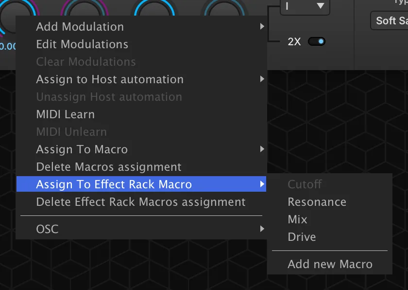
The overall level of the FX chain can be adjusted in the Tree view, or the chain can be disabled with the POWER button.
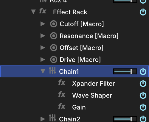
You can also create additional FX chains within a single Effect Rack by right-clicking the Effect Rack node in the TREE view and choosing ADD FX CHAIN. Chains are discrete and run in parallel, but utilize the same front panel for macros.
Filter
Tailor-made filters as Effect Racks.
MixXpander (screen example below) is a simple cutoff filter with mix control. Parallel and Stereo Xpander are made with two Xpander filters to create parallel or stereo filter effects.
CUTOFF (20–20,000 Hz) sets the frequency for the filter.
RESONANCE (0–100 %) adjusts how much emphasis is given to the cutoff frequency. MIX sets the balance between the dry (unaffected) and wet (affected) signal sent to the module’s output. DRIVE (−20–20 dB) sets the amount of overdrive used.
You can see the FX chains and edit the modules in the Tree view by choosing the node.
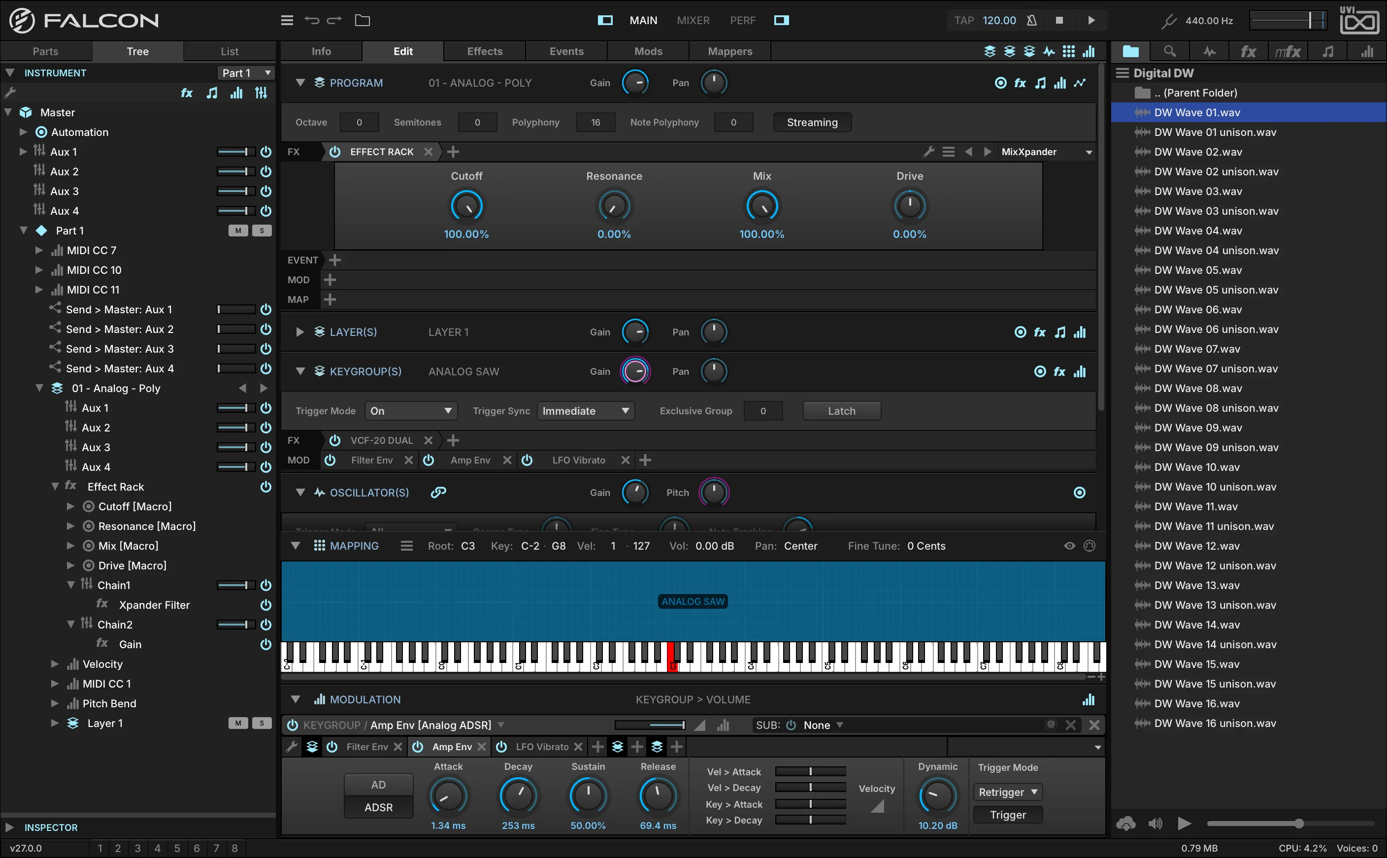
Fuzz4
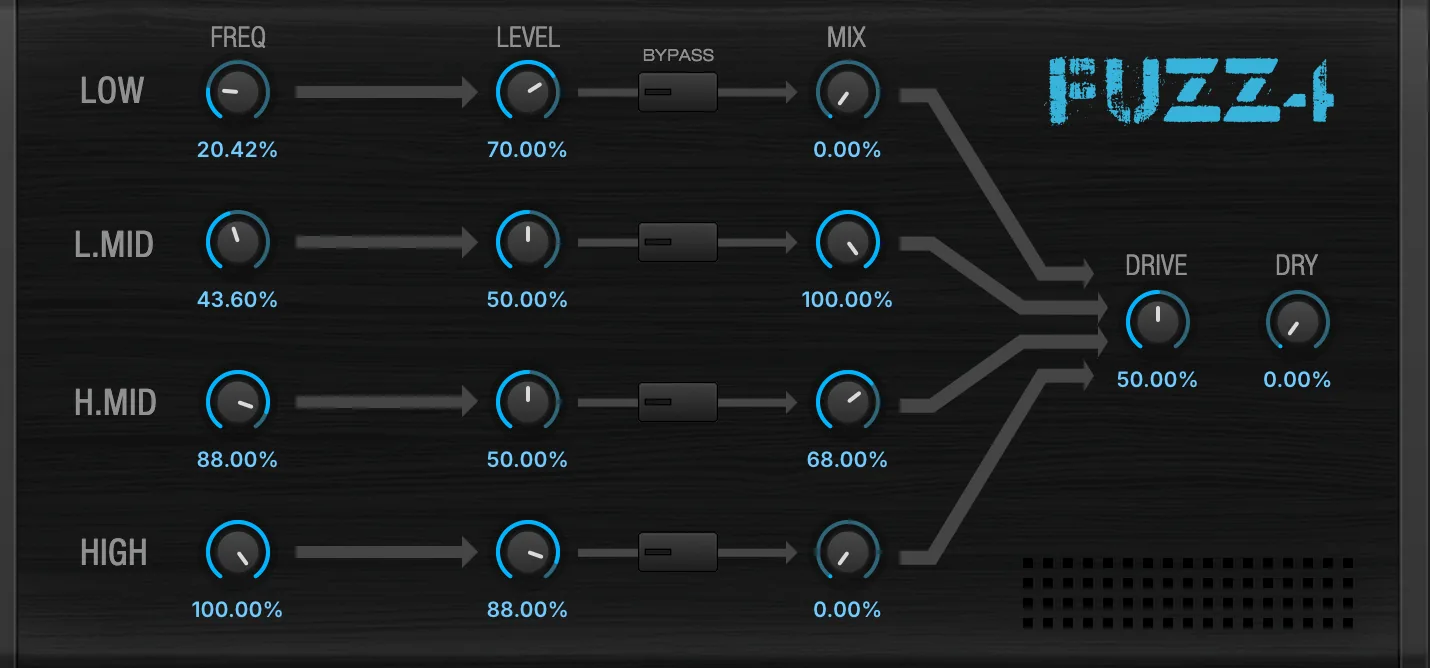
A 4-band distortion effect built from Wave Shaper and Xpander Filter modules.
FREQUENCY sets the band frequency. LEVEL sets the output volume of the band, BYPASS button enables or disables the band (FX chain), and MIX sets the balance between the dry (unaffected) and wet (affected) signal of the band.
DRIVE adjusts characteristics of the drive.
DRY sets the dry (unaffected) signal sent to the module’s output.
You can see the FX chains and edit the modules in the Tree view by choosing the node.
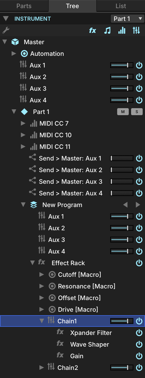
MaxMS
A Mid-Side Mastering module with High and Low bands for MID control.
Mid
COMP sets the compression amount. Mute the band with the MUTE switch, and the GAIN adjusts the band level.
CROSSOVER adjusts the frequency of the Low and High Mid bands.
Side
COMP sets the compression amount. Mute the band with the MUTE switch, and adjust the band level with GAIN.
You can see the FX chains and edit the modules in the Tree view by choosing the node.
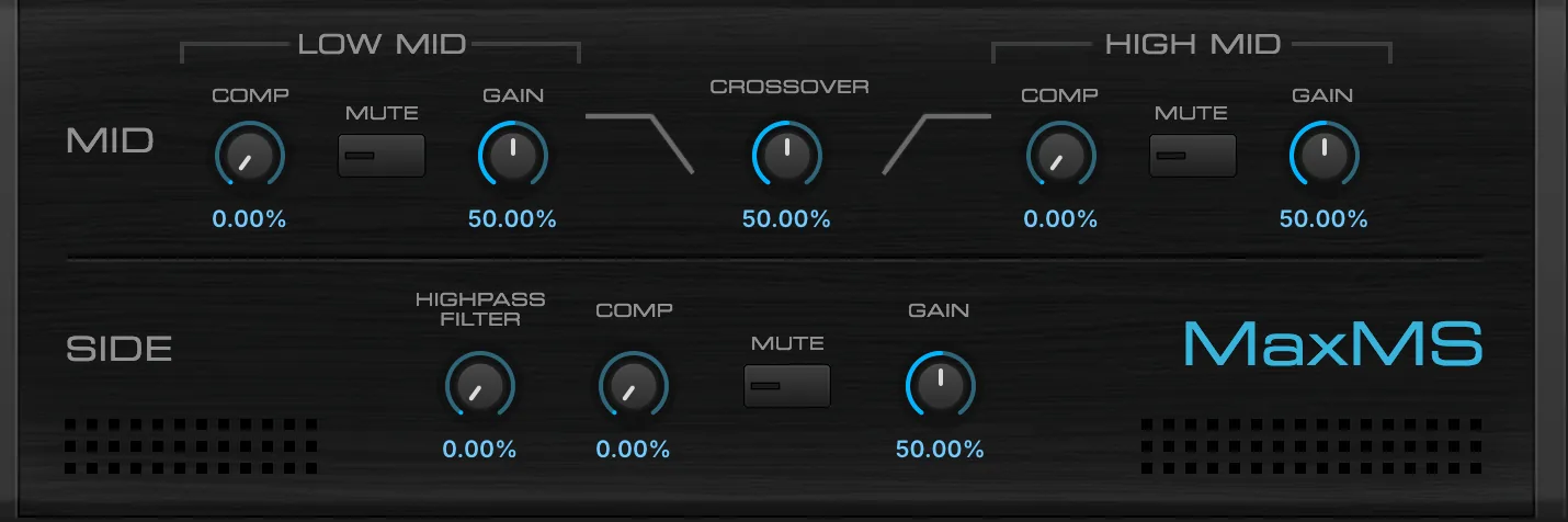
Feedback Machine

The Feedback Machine is a variant of the standard Effect Rack with a featured feedback loop, providing control over feedback amount, feedback injection delay, and overall mix amount.
For general instruction on using an Effect Rack see: Effects › Effect Rack.
Feedback Machine provides a featured feedback loop to your Chain. In its default state, Feedback Machine is identical to an empty Effect Rack in appearance and function, with the addition of 3 knobs on the front panel:
DELAY TIME (0.002–1 s) sets the time, in seconds, to delay the feedback signal before reinjection to the Chain.
FEEDBACK (0–100 %) sets the amount of the Chain’s output to reinject at its input (take care).
MIX (0–100 %) sets the wet/dry level of the effect.
Misc
Dispersor
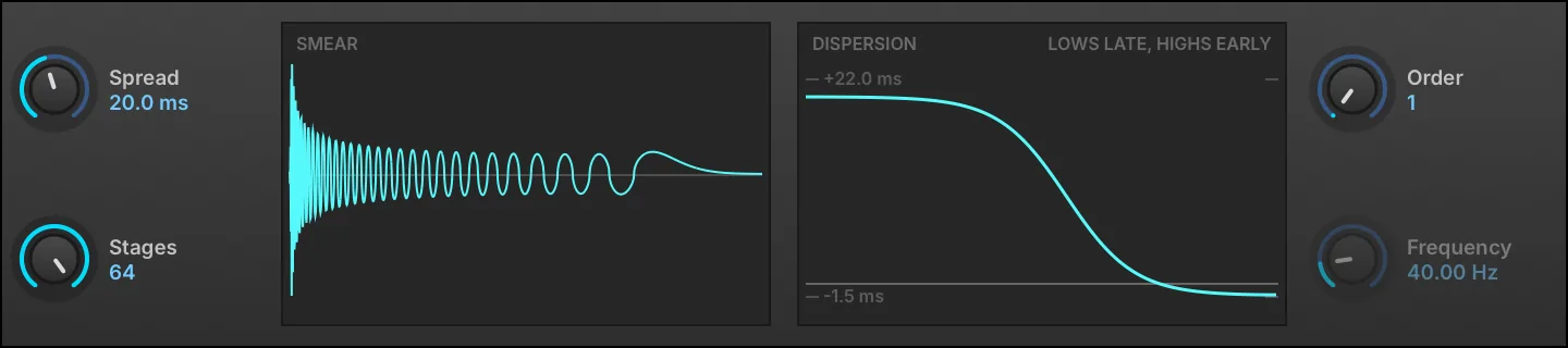
A transient smearing effect built from a chain of allpass filters, which delays each frequency by a different amount, with variable spread, frequency, order and stages.
Two displays sit between the controls. The left one, headed SMEAR, is the effect’s own impulse response, captured by running the current settings on an impulse rather than derived from them; it reads SMEAR (PART) when the smear has grown longer than the window can show. The right one, headed DISPERSION, plots group delay against frequency, measured against a linear-phase reference — a constant group delay disperses nothing, it is only latency — so the curve reads around a flat line the way an EQ does, with the extremes marked and labeled in milliseconds. At Order 1 it also reads LOWS LATE, HIGHS EARLY, the one direction that order can smear in.
SPREAD (0–1,000 ms) sets how far in time the transients are smeared.
STAGES (1–64) sets how many allpass stages are chained: more stages make a denser, smoother smear.
ORDER chooses first or second order. First order is the gentler smear and always runs lows late; second order is sharper and is what makes Frequency meaningful.
FREQUENCY (0–20,000 Hz) sets the center frequency of the dispersion curve. It applies to second order only, and is grayed out at Order 1.
Redux

A resampling effect useful for emulating the low-fidelity sound of various hardware units or extreme bit reductions.
FREQUENCY (200–44,100 Hz) sets the resampling frequency, with JITTER (0–100 %) introducing time variations to the resampling. BITS (1–32) sets the bit depth, and DITHER (0–200 %) sets the amount of dither (a type of low-level randomized noise).
TYPE chooses the style of resampling: DECIMATE inserts zeroes in between sampled values, and BLOCKER holds a sampled value until the next sampled value.
QUANTIZE LAW sets the type of quantization to one of two common algorithms: linear or mu-law (also known as μ-law).
Filter
FREQ (20–20,000 Hz) sets the frequency for the filter, and RES (0–100 %) adjusts how much the cutoff frequency is emphasized.
MODE chooses the type of filter: low-pass (LP), band-pass (BP), or high-pass (HP). POSITION chooses whether the filter is Off, before resampling (Pre), or after (Post).
Output
MIX (0–100 %) sets the balance between the dry (unaffected) and wet (affected) signal sent to the module’s output.
The ANTIALIASING toggle sets whether an anti-aliasing filter is enabled. When disabled, frequencies above half the resampling FREQUENCY may WRAP AROUND when resampled and cause unusual harmonics.
The SHAPING DISPLAY plots the module’s output waveform (blue) against a reference sine wave input (purple), so the effect of the current resampling, bit reduction, quantization and filter settings can be seen directly.
UVInyl

UVInyl is a vinyl simulation effect.
Choose the general vinyl characteristics with YEAR (1930, 1950, 1960, 1970, 1980, or 2000), RPM (33, 45, or 78 revolutions per minute), and amount of WEAR (0–100 %). Wear moves through eleven steps across its range, each one narrowing the record’s bandwidth and squashing its dynamics a little further.
Noise
To add noise to the record, add ELECTRICAL NOISE (−30–20 dB) or MECHANICAL NOISE (−30–20 dB) with their Gain controls.
Dust and Scratch
To add damage to the record, add DUST (−30–20 dB) or SCRATCH (−60–40 dB) with their Gain controls. The relative frequency of dust and scratches can be adjusted with the DUST AMOUNT (0–100 %) and SCRATCH AMOUNT (0–100 %) controls.
Output
The signal can be folded down to mono with the MONO toggle.
Legacy Effects
The Legacy FX modules were included in past versions of Falcon, UVI Player and MachFive. When older program and multi files are loaded, Legacy FX modules may be recalled.
For new programs and multis, it’s recommended to use the standard effects modules.
Delays
Dual Delay
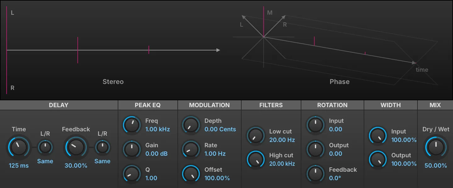
Dual Delay is a delay module with multiple controls for modifying one or both channels to produce a rich array of time-based effects, with an immersive interface to help visualize the stereo and phase adjustments being made.
Delay
TIME (0.001–5 s) sets the length of delay, in ms or bars/beats (if tempo-synced). FEEDBACK (0–100 %) chooses the percentage of signal fed back into the module. Both Time and Feedback have L/R controls that shorten one channel relative to the other: the display reads Same at the center, and L x or R x followed by a multiplier (0.10–1.00) applied to that channel only. Use 0.66 for dotted, 0.5 for half and 0.33 for triplet.
Peak EQ
A peak EQ located in the feedback loop. FREQ (20–20,000 Hz) sets the EQ frequency. GAIN (−20–20 dB) sets the EQ gain amount (+/-). Q (0.1–10) sets the filter’s bandwidth.
Modulation
DEPTH (0–20 ms) chooses a detune amount for the delay taps, and RATE (0.1–10 Hz) sets the speed of modulation. OFFSET (0–100 %) adjusts the phase offset of the delay line LFO.
Filters
The filters affect only the wet signal; the dry signal is not filtered. LOW CUT (20–4,000 Hz) rolls off lower frequencies, and HIGH CUT (1,000–20,000 Hz) rolls off higher frequencies.
Rotation
The Rotation section adjusts the phase of the INPUT (−1 to 1), OUTPUT (−1 to 1), and FEEDBACK signals.
Width
INPUT (0–100 %) adjusts the stereo spread of the signal input to the effect, and OUTPUT (0–100 %) adjusts the spread of the output signal.
Mix
DRY/WET knob sets the balance between the dry (unaffected) and wet (affected) signal sent to the module’s output.
Display
The display shows a visual representation of how the controls will affect the STEREO and PHASE output of the module.
FX Delay

FX Delay is a stereo delay with auto-panned stereo modulation.
DELAY TIME (0.01–10 s) sets the length of delay, in ms or bars/beats (if tempo-synced), and FEEDBACK (0–100 %) chooses the percentage of signal fed back into the module.
CUTOFF sets the type and amount of filter. At the center position, no filter is applied. To the right of center, a high-pass filter is applied, and further to the right raises the cutoff frequency. Likewise, further left of center applies a low-pass filter and drops the cutoff frequency.
The delay is also auto-panned; SPEED (0–20 Hz) controls the autopan rate, in Hz or bars/beats (if tempo-synced).
MIX (0–100 %) sets the balance between the dry (unaffected) and wet (affected) signal sent to the module’s output.
Fat Delay

Fat Delay uses multiple delay lines and diffusion to produce a dense delay tail.
DELAY TIME (0.01–10 s) sets the length of delay, in ms or bars/beats (if tempo-synced), and FEEDBACK (0–100 %) chooses the percentage of signal fed back into the module.
DIFFUSION (0–100 %) sets the density of the delay tap.
CUTOFF sets the type and amount of filter. At the center position, no filter is applied. To the right of center, a high-pass filter is applied, and further to the right raises the cutoff frequency. Likewise, further left of center applies a low-pass filter and drops the cutoff frequency.
MIX (0–100 %) sets the balance between the dry (unaffected) and wet (affected) signal sent to the module’s output.
Ping Pong Delay

Ping Pong Delay is a standard delay with additional stereo processing.
DELAY TIME (0.01–10 s) sets the length of delay, in ms or bars/beats (if tempo-synced), and FEEDBACK (0–100 %) chooses the percentage of signal fed back into the module.
CUTOFF sets the type and amount of filter. At the center position, no filter is applied. To the right of center, a high-pass filter is applied, and further to the right raises the cutoff frequency. Likewise, further left of center applies a low-pass filter and drops the cutoff frequency.
SPREAD (±100 %) controls the stereo spread of the module’s output. At zero, the output is mono; negative values feed the input to the left channel first, and positive values to the right channel first.
MIX (0–100 %) sets the balance between the dry (unaffected) and wet (affected) signal sent to the module’s output.
Simple Delay

Simple Delay is a general-purpose delay.
DELAY TIME (0–10 s) sets the length of delay, in ms or bars/beats (if tempo-synced), and FEEDBACK (0–100 %) chooses the percentage of signal fed back into the module.
CUTOFF sets the type and amount of filter. At the center position, no filter is applied. To the right of center, a high-pass filter is applied, and further to the right raises the cutoff frequency. Likewise, further left of center applies a low-pass filter and drops the cutoff frequency.
MIX (0–100 %) sets the balance between the dry (unaffected) and wet (affected) signal sent to the module’s output.
Stereo Delay

Stereo Delay offers a configurable stereo delay with separate delay paths for the left and right channels.
The left and right channels have independent delay time assignments; LEFT DELAY TIME (0–10 s) and RIGHT DELAY TIME (0–10 s) set the length of each channel’s delay, in ms or bars/beats (if tempo-synced). FEEDBACK (0–100 %) chooses the percentage of signal fed back into the module.
CUTOFF sets the type and amount of filter. At the center position, no filter is applied. To the right of center, a high-pass filter is applied, and further to the right raises the cutoff frequency. Likewise, further left of center applies a low-pass filter and drops the cutoff frequency.
MIX (0–100 %) sets the balance between the dry (unaffected) and wet (affected) signal sent to the module’s output.
Reverb
Gate Reverb

Gate Reverb provides a gate for cutting off the reverb decay abruptly.
PRE DELAY (0.01–2 s) sets the amount of delay before the wet signal is heard, in ms or bars/beats (if tempo-synced), and DECAY TIME (0–10 s) sets the duration of the reverb decay. GATE TIME (0.05–1 s) sets the time duration, in ms or bars/beats (if tempo-synced), until the gate is applied to the decaying signal.
HIGH DAMP (0–100 %) sets the amount of dampening applied to high frequencies.
MIX (0–100 %) sets the balance between the dry (unaffected) and wet (affected) signal sent to the module’s output.
Plain Reverb

Plain Reverb is a general-purpose reverb.
DECAY TIME (0–10 s) sets the duration of the reverb decay, and HIGH DAMP (0–100 %) chooses the amount of dampening applied to high frequencies.
MIX (0–100 %) sets the balance between the dry (unaffected) and wet (affected) signal sent to the module’s output.
Predelay Verb

Predelay Verb is a standard reverb fed through a delay line.
PRE DELAY (0.01–2 s) sets the amount of delay before the wet signal is heard, in ms or bars/beats (if tempo-synced), and DECAY TIME (0–10 s) sets the duration of the reverb decay. HIGH DAMP (0–100 %) chooses the amount of dampening applied to high frequencies.
MIX (0–100 %) sets the balance between the dry (unaffected) and wet (affected) signal sent to the module’s output.
Simple Reverb

Simple Reverb provides an optional low-pass or high-pass filter before the signal is fed into the reverb.
CUTOFF sets the type and amount of filter. At the center position, no filter is applied. To the right of center, a high-pass filter is applied, and further to the right raises the cutoff frequency. Likewise, further left of center applies a low-pass filter and drops the cutoff frequency.
DECAY TIME (0–10 s) sets the duration of the reverb decay, and HIGH DAMP (0–100 %) chooses the amount of dampening applied to high frequencies.
MIX (0–100 %) sets the balance between the dry (unaffected) and wet (affected) signal sent to the module’s output.
Modulation
Chorus

Chorus is a classic chorus, where the input signal is combined with multiple time- and pitch-modulated variations of the input signal for a shimmering unison effect.
SPEED (0.01–10 Hz) sets the speed of the modulation (in Hz, or bars/beats if tempo-synced), DELAY TIME (0–1 s) adjusts the amount of delay applied, and DEPTH (0–100 %) sets the depth of the effect.
MIX (0–100 %) sets the balance between the dry (unaffected) and wet (affected) signal sent to the module’s output.
Cross Phaser

Cross Phaser is a phaser that also applies auto-panning to produce a wider and more varied effect.
SPEED (0–10 Hz) sets the speed of the modulation (in Hz, or bars/beats if tempo-synced), and MIN FREQ (100–20,000 Hz) and MAX FREQ (100–20,000 Hz) set the minimum and maximum frequencies of the frequency sweep.
DEPTH (0–100 %) sets the depth of the effect, and FEEDBACK (0–100 %) sets the percentage of signal fed back into the module.
Phaser

Phaser is a classic phaser effect, where the input signal is phase modulated and fed back onto itself.
SPEED (0–10 Hz) sets the speed of the modulation (in Hz, or bars/beats if tempo-synced), and MIN FREQ (100–20,000 Hz) and MAX FREQ (100–20,000 Hz) set the minimum and maximum frequencies of the frequency sweep.
DEPTH (0–100 %) sets the depth of the effect, and FEEDBACK (0–100 %) sets the percentage of signal fed back into the module.
Rotary
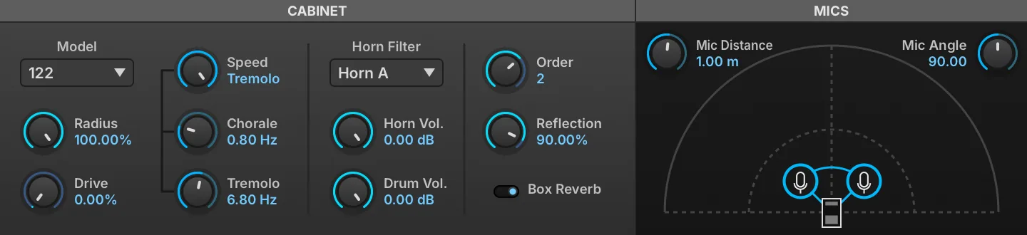
Rotary is a highly customizable speaker emulation effect modeled after the classic two-way rotating designs created for electric organs in the 1940s.
Cabinet
MODEL changes the cabinet type. RADIUS (0–100 %) sets the size of the cabinet. DRIVE (0–100 %) sets the amount of overdrive in the cabinet circuit.
SPEED sets the rotary style: BRAKE = none, CHORALE = slow speeds, TREMOLO = fast speeds.
Chorale and Tremolo speeds are controllable with the CHORALE (0.1–3 Hz) and TREMOLO (3–10 Hz) knobs below.
HORN FILTER sets the filter mode of the cabinet’s horn. HORN VOL (0–1) adjusts the rotating horn level. DRUM VOL (0–1) adjusts the rotating drum level.
ORDER (0–3) sets the number of box reflections being simulated. REFLECTION (0–100 %) sets the mix amount for the reflected signal.
BOX REVERB arms or disables a reverb on the cabinet.
Mics
MIC DISTANCE (0–10) sets the distance of the mics to the cabinet.
MIC ANGLE (0–180) sets the angle between the mics relative to the cabinet.
Filter
Auto Wah

Auto Wah is a wah pedal effect, with its filter frequency set automatically from the module’s input level.
GAIN (0.125–2) sets the input level to the module. SENSITIVITY (0.1–0.9) sets the intensity of the auto wah filter, and the Q (0–1) control sets the filter’s shape. DRIVE (0–1) applies post-filter overdrive.
FX Filter

The FX Filter module has two filters, low-pass and high-pass, applied in series.
LOW FREQ enables and sets the cutoff frequency for the low-pass filter; likewise, HIGH FREQ enables and applies the high-pass filter. The LOW Q (0–1) and HIGH Q (0–1) controls set the shape of each filter band.
Talkbox

Talkbox simulates the vowel shaping and filtering of a classic talkbox effect pedal.
FILTER MODE chooses the type of filter: low-pass (LP), high-pass (HP), or band-pass (BP). VOWEL MODE chooses the vowel sound for the filter.
CUTOFF (20–20,000 Hz) sets the frequency for the filter; the note name corresponding to the frequency is also displayed, for example, 2.00 KHZ (B5). RESONANCE (0–100 %) adjusts how much the cutoff frequency is emphasized.
Equalizer
2 Band EQ

The 2 Band EQ has Low and High bands.
Both bands have a FREQ control for setting their central frequency and a GAIN control for boosting or cutting around that frequency.
3 Band EQ

The 3 Band EQ has Low, Mid, and High bands. The Low and High bands have fixed frequency assignments, while the Mid band is adjustable.
The Mid band has a MID FREQ (120–12,000 Hz) control for setting the band’s central frequency and a MID Q (0–1) control for the band’s shape. Each of the three bands has a GAIN control for boosting or cutting its frequency.
8 Band EQ
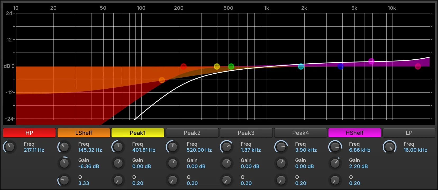
The 8 Band EQ is a parametric EQ with multiple types of bands, all laid out on a large, graphical display.
The eight bands are:
-
two rolloffs: high-pass (HP) and low-pass (LP).
-
two shelves: low-shelf (LSHELF) and high-shelf (HSHELF).
-
four peaks: PEAK1, PEAK2, PEAK3, PEAK4.
Each band can be enabled or bypassed by pressing its name. When enabled, the button is colored in.
All bands have a fully variable FREQ (10–20,000 Hz). The high-pass and low-pass bands have a fixed slope, while the remaining shelf and peak bands have adjustable GAIN (−30–20 dB) and Q (0.2–12).
In addition to the knobs and toggle switches, the bands can also be edited graphically in the frequency graph:
-
Press and drag a point to adjust its frequency by dragging right/left, or its gain by dragging up/down.
-
Press and drag a band’s color bars to adjust Q.
-
Right-click a point to enable/disable the band.
-
Double-click a point to return it to its default value.
-
When a band is selected, an information box is displayed in the upper left. As the band is adjusted, its Gain, Frequency, and Q values update in real time.
To view a larger graph, drag the bottom edge of the module to resize it.
Press the EXTERNAL WINDOW button in the module title bar to open the graph in a separate window to view it even larger.
Amp & Stereo
Rotary Simple

Rotary Simple is a single-speaker emulation of a rotary speaker.
SPEED (0–20 Hz) sets the rate of the speaker rotation, and DEPTH (1–100 %) sets the intensity of the effect; at higher Depth values, the pitch is also markedly affected.
Miking the speaker is also simulated, with MIC DISTANCE (1.1–20) setting the distance of the mic from the speaker.
MIX (0–100 %) sets the balance between the dry (unaffected) and wet (affected) signal sent to the module’s output.
Rotary Speaker

Rotary Speaker is a dual-speaker emulation of a rotary speaker, with an adjustable crossover.
CROSS FREQUENCY (20–10,000 Hz) sets the crossover point for the Low and High frequency bands. LOW SPEED (0–20 Hz) and HIGH SPEED (0–20 Hz) set the rate of the speaker rotation for each band, and DEPTH (1–100 %) sets the intensity of the effect; at higher Depth values, the pitch is also markedly affected.
Miking the speaker is also simulated, with MIC DISTANCE (1.1–20) setting the distance of the mic from the speaker.
Drive & Distortion
Double Drive

Double Drive is a filter sandwiched by two drive stages.
PRE DRIVE (0–100 %) sets the initial amount of overdrive, followed by the filters. HIGH FREQ and LOW FREQ controls set the amount of high-pass and low-pass filter applied (if any). Post-filter drive is applied with POST DRIVE (0–100 %), with GAIN (0–1) providing the final output level adjustment.
UVI Drive

UVI Drive is a drive module with a post-drive UVI Filter included.
DRIVE (0–100 %) sets the initial amount of drive applied, followed by the filter.
CUTOFF sets the type and amount of filter. At the center position, no filter is applied. To the right of center, a high-pass filter is applied, and further to the right raises the cutoff frequency. Likewise, further left of center applies a low-pass filter and drops the cutoff frequency. The Q (0–1) control sets the filter’s shape.
GAIN (0–1) provides the final output level adjustment.
Dynamics
Compressor

Compressor provides standard dynamics compression.
THRESHOLD (0–1) sets the level at which the compressor will be applied; when applied, RATIO (0–1) sets the slope above the threshold: 1 leaves the signal uncompressed (the default), lower values compress harder, and 0 holds the signal at the threshold. ATTACK (0.0001–0.1 s) and RELEASE (0.01–1 s) set the speed at which the compressor begins or stops processing the signal after it has crossed the threshold.
MAKEUP (1–16) applies a manual gain adjustment to compensate for the gain reduction of the compressor.
MIX (0–100 %) sets the balance between the dry (unaffected) and wet (affected) signal sent to the module’s output.
Limiter

Limiter is a standard limiter, compressing the signal with a fixed ratio that is higher than the ratios available with the Compressor.
GAIN (0.25–4) sets the input level to the module. THRESHOLD (0.1–1) sets the level at which limiting will be applied, and CEILING (0.1–1) sets the maximum output level. RELEASE (0–1 s) sets the speed at which the limiter stops processing the signal after it has fallen below the threshold.
MIX (0–100 %) sets the balance between the dry (unaffected) and wet (affected) signal sent to the module’s output.
UVI Mastering

UVI Mastering is a mastering processor for stereo mixes, such as Falcon’s main outs. It provides three-band tube saturation, a compressor and a limiter.
UVI Mastering has Low, Mid, and High bands. The crossover points between the bands are set with the LOW/MID FREQ (20–20,000 Hz) and MID/HIGH FREQ (20–20,000 Hz) controls.
Each band has a VOLUME (0.25–2) control, which sets the gain of the band before its tube saturation. TUBE AMOUNT (0–15) sets the saturation of every band. The bands are then summed and fed to a compressor with a fixed 4:1 ratio and automatic make-up gain, set with COMP ATTACK (0–500 ms) and COMP THRESHOLD (−20–0 dB), and finally to a limiter set by LIMITER THRESHOLD (−20–0 dB).
Misc
Beat Repeat

Beat Repeat slices the incoming audio on the grid that you specify, and when activated will repeat the most recent slice. This enables glitch effects and variations in a live performance or looped samples.
ACTIVE enables beat repeating; the most recent beat will be repeated until beat repeating is disabled. Once disabled, playback continues from where it left off.
TIME (0.001–4 s) sets the length of time that will be repeated, in ms or bars/beats (if tempo-synced).
MIX (0–100 %) sets the balance between the dry (unaffected) and wet (affected) signal sent to the module’s output.
FADETIME (0–0.05 s) sets the length of the fade applied at the start and end of each repeat, to soften the loop boundary.
Redux

Redux is a resampler for creating lo-fi effects such as extreme bit reduction.
Resampling
FREQUENCY (200–44,100 Hz) sets the resampling frequency, with JITTER (0–100 %) introducing time variations to the resampling. BITS (1–32) sets the bit depth, and DITHER (0–100 %) sets the amount of dither (a type of low-level randomized noise).
TYPE chooses the style of resampling: DECIMATE inserts zeroes in between sampled values, and BLOCKER holds a sampled value until the next sampled value.
QUANTIZE LAW sets the type of quantization to one of two common algorithms: linear or mu-law (also known as μ-law).
The ANTIALIASING toggle sets whether an anti-aliasing filter is enabled. When disabled, frequencies above half the resampling FREQUENCY may WRAP AROUND when resampled and cause unusual harmonics.
Filter
FILTER POSITION chooses whether the filter is off, before resampling (pre), or after (post). FILTER MODE chooses the type of filter: low-pass (LP), high-pass (HP), or band-pass (BP).
FILTER FREQ (20–20,000 Hz) sets the frequency for the filter, and FILTER RES (0–100 %) adjusts how much the cutoff frequency is emphasized.
Output
MIX (0–100 %) sets the balance between the dry (unaffected) and wet (affected) signal sent to the module’s output.
Ring Modulator

Ring Modulator combines the input signal with a modulation frequency, and both subtracts and adds the modulation frequency to the input frequency. For example, with an input of 600 Hz and a modulation frequency of 250 Hz, the output will include both 350 Hz (600 minus 250) and 850 Hz (600 plus 250).
FREQ (0.1–2,000 Hz) sets the frequency of the modulation signal.
MIX (0–100 %) sets the balance between the dry (unaffected) and wet (affected) signal sent to the module’s output.
Robotizer

Robotizer starts with a ring modulator, with some additional modulations.
FREQ (0.1–2,000 Hz) sets the frequency of the ring modulation, and DEPTH (0–100 %) adjusts the intensity of the modulation. FM (0.25–20 Hz) controls a modulation signal that modifies the ring modulation frequency.
CUTOFF sets the type and amount of filter. At the center position, no filter is applied. To the right of center, a high-pass filter is applied, and further to the right raises the cutoff frequency. Likewise, further left of center applies a low-pass filter and drops the cutoff frequency.
MIX (0–100 %) sets the balance between the dry (unaffected) and wet (affected) signal sent to the module’s output.
UVI Destructor

UVI Destructor is a resampler and bit reducer, with optional overdrive and filter following the bit depth and sample rate reduction.
BIT SIZE (1–24) sets the bit depth, and SAMPLE RATE (2,000–48,000 Hz) sets the resampling frequency.
DRIVE (0–100 %) sets the amount of pre-filter overdrive applied.
CUTOFF sets the type and amount of filter. At the center position, no filter is applied. To the right of center, a high-pass filter is applied, and further to the right raises the cutoff frequency. Likewise, further left of center applies a low-pass filter and drops the cutoff frequency.
MIX (0–100 %) sets the balance between the dry (unaffected) and wet (affected) signal sent to the module’s output.
Event Processors
Falcon’s Event section provides control over pre-synthesis data, namely the manipulation, analysis or generation of MIDI. Event processors can do anything from arpeggiating incoming notes or strumming them like a guitar to applying micro tunings, playing back MIDI files or creating generative sequences.
MIDI processors that act before synthesis; script processors extend them in Lua.
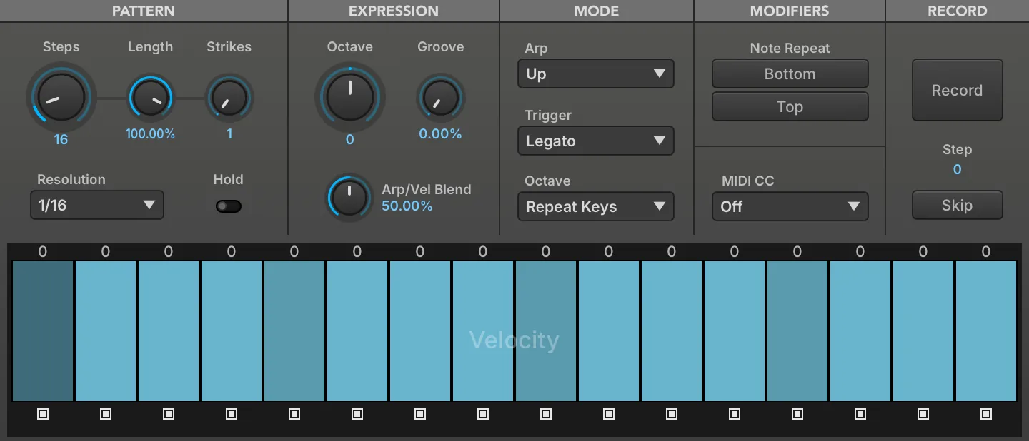
A step arpeggiator that plays held notes in a programmable, tempo-synced pattern, with per-step length, gate, pitch and velocity and 28 performance modes. It turns chords into rhythmic sequences, and its MIDI CC lane can drive modulation in time with them.
Read more ↓
An event processor that sends MIDI from any point in a patch to external software or hardware, on each event’s own channel or on a channel from 1 to 16. It lets Falcon’s notes and sequences play other instruments.
Read more ↓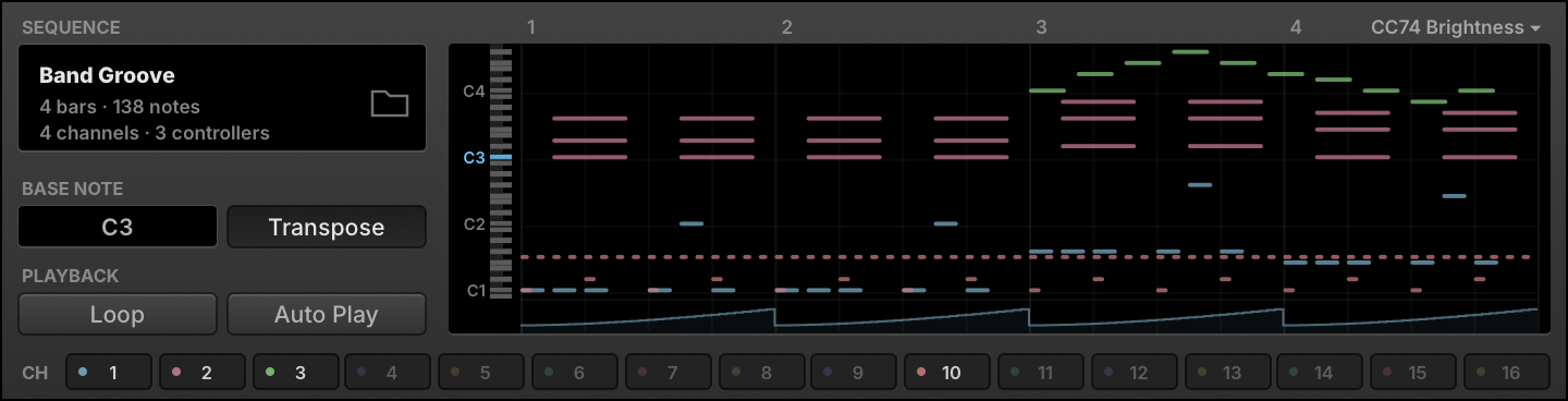
An event processor that plays back a Standard MIDI File, tempo-synced with Falcon, when its base note is played, once or looped. It adds prerecorded phrases and patterns to a program.
Read more ↓
An event processor that replaces standard twelve-tone equal temperament with alternate tunings imported from Scala files. It suits historical temperaments and the tunings of other musical traditions.
Read more ↓
An event processor that runs a Lua script, with the script’s own controls below its standard ones. It extends Falcon with custom event processing; the factory scripts cover analysis, harmonization, performance, sequencing and more.
Modules in this category Read more ↓- Cartesian Sequencer
- Chip Arp
- Drum Sequencer
- Euclidean Drum Sequencer
- Euclidean Keys Sequencer
- Euclidean Tonal Sequencer
- Gate Mod
- Gate Mod Bernoulli
- Gate Mod Poly
- MIDI CC LFO
- Motion Grid
- Node Arp
- Ostinato Arp
- Polyphonic Sequencer
- Probability Arp
- Rain Sequencer
- Slice Remixer
- Snowflakes
- Step Arp
- Step Line
- Warp Sequencer
- Waterfall
- Wave Sequencer
- Invert Pitch
- Limit Range
- Mapper
- MIDI CC Filter
- MIDI CC Redirect
- MIDI CC Smoother
- MIDI Delay
- MIDI Monitor
- MIDI Record
- MPE
- Pgm Change Switcher
- Transpose
- Velocity Test
Arpeggiator
Arpeggiator
The arpeggiator is a classic synthesizer effect which modifies incoming notes and plays them in a programmable pattern to create a dynamic sequence. Falcon’s Arpeggiator provides many advanced features such as per-step length, gate, pitch and velocity as well as 28 different performance modes.
Pattern
STEPS (1–128) sets the number of steps in the sequence, LENGTH (0–110 %) sets the gate length of each step, lower values result in more staccato and values >100% will slightly overlap the following note. STRIKES (1–4) sets the number of times each step will be triggered, values above 1 will repeat each step that many times before proceeding.
RESOLUTION sets the step length relative to the global BPM set in the host DAW, from 32 bars down to 64th note triplet. HOLD is a manual latch, enable it to infinitely sustain any active notes, disable it to end them.
Expression
OCTAVE (−6 to 6) sets the octave range of the pattern, GROOVE (0–100 %) sets the amount of groove to apply to the pattern, and ARP/VEL BLEND (0–100 %) sets the blend of the arpeggiator velocity value with the original note-on velocity values. At zero percent, the resulting velocity is fully controlled by the note velocity setting of the arpeggiator, and at 100% by the incoming note-on velocity values.
Mode
ARP selects the arpeggiator pattern to play, from a simple upward progression to zigzags, spirals, and more.
TRIGGER sets the arpeggiator trigger mode:
-
NOTE: Each note resets the arpeggiator position to the first step.
-
LEGATO: When multiple notes are played simultaneously, each new note continues from the current step.
-
SONG POSITION: The arpeggiator continually cycles, and any notes played are triggered at the current step.
OCTAVE (Repeat Pattern / Repeat Keys — not to be confused with the Expression OCTAVE knob above) sets whether the pattern of notes will be repeated individually within each octave (Repeat Pattern) or whether the pattern will be completed once in total across all notes in all octaves (Repeat Keys).
Modifiers
NOTE REPEAT (BOTTOM / TOP) repeats the top or bottom-most note of the pattern.
MIDI CC
Sets the controller number (0–127) that the MIDI CC lane sends, or Off to disable it.
Record
Allows you to record custom arpeggiator sequences using an external MIDI input, or using the built-in virtual keyboard in Falcon.
RECORD click to enable step recording, click again to finish.
STEP displays the current step while recording, and total step count when finished.
SKIP while recording, inserts a blank step.
Step Grid
Use the STEP GRID to set the value for each step. There are three independent layers to the step grid: VELOCITY, PITCH, and MIDI CC.
Each layer holds one parameter per step, so the sequence can be automated value by value. VELOCITY (0–100 %) sets the level a step plays at, which becomes a MIDI velocity of 1 to 127 before ARP/VEL BLEND mixes it with the incoming note velocity, while PITCH and MIDI CC hold the per-step values described below.
Step State Beneath each step is a toggle that can be pressed to set the step state. When enabled, the step outputs the value displayed in the bar above; when disabled, the step does not output any value.
Additionally, you can merge a step with the one before it to create steps that are longer than one step of the grid. To merge a step, hold the Shift key when pressing the step state button. The step state button for merged states is red.
Alternatively, you can tie a step to the one that follows it; both steps keep their own value, but the second is triggered in a legato style. To tie a step, hold the Alt/Option key when pressing the step state button. The step state button for tied states is blue.
STEP STATE is a parameter with four values. Off leaves the step silent while the sequence carries on to the next one, On plays a note, Merged gives the step’s time to the note before it rather than playing one of its own, and Tied plays a note that is released only once the following step has started, which is what produces the legato overlap.
-
Right-click anywhere on the step grid to change the sequencer page: Velocity, Pitch, or MIDI CC.
-
Click-and-drag across steps to draw values in a continuous motion.
-
Alt/Option-drag across steps to set their values to zero.
-
Scroll over a step to nudge its value up or down.
-
Double-click a step to numerically set the value.
Step Value
The size of the vertical bar within the step determines the step’s value. The larger the bar, the higher the value. Note that when viewing the Pitch layer, the bar is bipolar, with zero displayed in the vertical center of the step. To change the duration of the step, hold the Shift key while dragging the bar horizontally within its step.
The duration set that way is the STEP SIZE parameter (0–100 %), a proportion of the slot the step occupies in the grid. It multiplies the global LENGTH setting rather than replacing it, so a step at 50 % sounds for half as long as LENGTH alone would give it, and where steps are merged the note is sized over the whole merged span.
Pitch Offset
The values of the Pitch Layer are the offset applied to the incoming note, in semitones (−48 to 48), and are displayed as text above each step. You can also edit these values directly for more precise control.
MIDI CC
The values of the MIDI CC Layer are set as values from 0–127. You can double-click steps for precise control.
Every step that is not off sends its value when the sequence reaches it, merged steps included, as long as the MIDI CC selector is not set to Off.
MIDI Out
MIDI Out
Take control of external software/hardware directly from Falcon, at any point in your patch.
Set MIDI CHANNEL for output, select AS IS to leave each event on the channel it arrived on, or select any channel from 1 - 16.
MIDI Player
MIDI Player
The MIDI Player module plays back a Standard MIDI File, tempo-synced with Falcon.
To load a MIDI file, press the BROWSE button and choose a Standard MIDI File using the standard file browser, or drag-and-drop a .mid file onto the module. When a MIDI file is loaded, its name is displayed next to SEQUENCE NAME.
The BASE NOTE (0–127) chooses which note will trigger playback of the MIDI sequence. Other notes will play back as usual. When TRANSPOSE is enabled, every note will trigger playback of the MIDI sequence, transposed relative to the Base Note. When disabled, only the Base Note will trigger playback.
When the MIDI file is triggered, it will play back once. If LOOP is enabled, the MIDI file will be looped continuously. Additionally, AUTOPLAY can be enabled to automatically begin MIDI file playback when Falcon begins playing.
By default, the MIDI Player will play back all sixteen channels saved in the MIDI file. Press a channel’s BYPASS button to bypass it.
Micro Tuner
Micro Tuner
The Micro Tuner provides alternate tunings to the standard twelve-tone equal temperament tuning.
The NOTE GRID displays the mapping of each note in each octave. In standard tuning, each note is mapped to a whole number: C-2 = 0.00, C#-2 = 1.00, D-2 = 2.00, and so on. The note grid is display only; to edit the tuning assignments, import Scala files as described below.
The Micro Tuner module’s preset menu has three additional items in its Preset File menu:
-
IMPORT SCALA TUNING: Import a .scl file.
-
IMPORT SCALA MAPPING: Import a .kbm file.
-
IMPORT ANAMARK TUNING: Import a .tun file.
You can also drag-and-drop .scl, .kbm, and .tun files directly onto the module.
For more information on Scala, see: http://www.huygens-fokker.org/scala.
Script Processor
Script Processor
The Script Processor module provides general event processing capabilities beyond the specific event processors described earlier.
This module has some standard controls at the top, with the script-defined controls below.
Standard Controls
To load a script, press the LOAD A SCRIPT button and choose a UVIScript file from the standard file browser. When a script file is loaded, its SCRIPT NAME is displayed in the center of the script module title bar, and its script-defined controls will be displayed below.
To edit the script file, press the EDIT SCRIPT IN EXTERNAL EDITOR button and the script file will be opened in your default text editor application.
If you would like to add a password to the current script, press the PROTECT SCRIPT button and enter a password. After a script is protected, you must enter the script password to open the script for editing.
Press the RELOAD CURRENT SCRIPT button to reload the current script from disk, and reset its parameters to their default values. Hold the Alt/Option key while reloading to keep the current state of the script parameters. The WATCH FOR SCRIPT CHANGES option will automatically reload the script whenever the script file is modified; this can be useful while developing a script and making repeated changes.
The script console displays debug and print messages and is useful for debugging scripts. Toggle the SHOW/HIDE CONSOLE OUTPUT button to show or hide the script console. Press the CLEAR CONSOLE OUTPUT button to clear the current console messages.
Script-Defined Controls
The script itself defines what sort of controls will be displayed. This includes knobs, buttons, menus, and other controls similar to those seen in other Falcon modules.
More Information
For more information on UVIScript, see: Scripting in Lua.
Analysis
Chord Recognition

Chord recognition: Names chord currently played.
CHORD displays the chord name currently played.
Virtual Pitch

Virtual Pitch: Real-time virtual pitch detection.
VIRTUAL PITCH displays the most likely root of the notes you are holding — the pitch class with the strongest virtual-pitch score.
VIRTUAL PITCH 2 displays the second most likely root — the runner-up interpretation of the same chord.
CHROMATIC DISPLAY shows the virtual-pitch strength of all twelve chromatic pitch classes, scaled so the strongest reads full height; the tallest bar is the root shown in VIRTUAL PITCH.
Effects
Ensemble

Play 5 voices using adjacent detuned sample-based key zones.
PAN SPREAD sets the stereo spread of the ensemble voices.
TIME SPREAD sets the time interval of the ensemble voices.
MIDI Pitch Delay

Classic MIDI event delay with pitch drift support.
DECAY sets the decay time of the effect.
TARGET PITCH sets the pitch shift amount for incoming notes.
RAMP TIME sets the ramp time of the effect.
SPEED sets the speed of the delay.
JITTER (0–100 %) randomizes the time between repeats, by up to ± the SPEED delay time at 100 %.
MIX sets the mixing level (velocity) of the effect.
Note Pan

Generate pan values for each key pressed with fixed and random options.
MODE sets the panning mode per note.
-
FIXED outputs the fixed stereo position set by the note’s dial.
-
ALT alternates the pan left and right with each keypress; the dial sets the depth of the alternation.
-
RAND outputs a random pan position with each keypress; the dial sets the depth of the randomization.
LINK enable to adjust all note parameters simultaneously.
Shepard

Shepard tone effect.
PARTIALS sets the number of partials.
STEP sets the number of steps per partial.
SPEED sets the speed of the pitch change.
DIRECTION sets the direction (up or down) and depth of pitch change.
Tape Mod

Vary your pitch with wow and flutter emulation for a lo-fi vibe.
FLUTTER FREQUENCY sets the flutter frequency and DEPTH sets the flutter modulation depth.
WOW FREQUENCY sets the wow frequency and DEPTH sets the wow modulation depth. CC sets the MIDI CC number for real-time control.
Timbre Shifting

Use a pitched adjacent sample-based key zone to change the instrument timbre.
SHIFT changes tonal color based on the adjacent samples.
Tremolo

A MIDI volume modulator.
FREQUENCY sets the speed of the effect.
Unison

Play up to 10 detuned voices.
NUMVOICES sets the number of the unison voices. DETUNE sets the interval spacing of the voices in cents.
Vibrato

A MIDI pitch modulator.
FREQUENCY sets the speed of the effect. DEPTH sets the amount of the effect.
Harmonization
Chord Bank
Create and assign chords to each MIDI key independently.
Select a root KEY and preset from the CHORD PRESET menu, or manually create and assign your own.
The UPPER KEYBOARD shows your MIDI input, use this to select a key to assign notes to. A GREEN key indicates there is an existing, custom note assignment; RED indicates the key is selected.
The LOWER KEYBOARD will display the note assignments for the key currently selected in the UPPER KEYBOARD, the keys currently assigned will show in RED.
To create or edit assignments using a mouse: Select a key in the UPPER KEYBOARD and then make assignments in the LOWER KEYBOARD.
To create or edit assignments using a MIDI keyboard as input:
Click MIDI SELECT, then press a key on your keyboard to select a note - it will show as RED in the UPPER KEYBOARD to indicate it’s active.
Click CHORD LEARN, then press keys on your keyboard to assign or unassign them - they will show as RED in the LOWER KEYBOARD to indicate they are assigned.
Use the ARROW KEYS (< and >) below each keyboard to shift the notes left or right.
Chord Generator
Instantly unlock complex chords and arpeggios. Map 7 customizable chords to single keys, explore a vast library of presets and progressions, and add rhythmic variation with a per-note step-sequencer for endless harmonic inspiration.
PRESET recalls a complete Chord Generator configuration across all 7 chord slots at once. You can scroll through these quickly using the < and > buttons.
KEY selects the global root key. LOCK prevents key changes when selecting presets.
CHORD SLOT Click a slot or press the MIDI note to display the corresponding editor.
LINK icon allows you to adjust the same parameters across all chord slots at once.
The top row holds the settings of the selected chord slot:
CHORD PRESET sets the chord voicing for the currently selected chord slot only, chosen from a number of useful premade configurations. You can scroll through these quickly using the < and › buttons.
NOTE sets the root note of the chord as indicated on the slot labels.
VEL OFFSET, TIME and CURVE set the offset of the incoming note velocity, time and time offset curve.
REPEATER (power) global bypass for note repeat effects. Click the RANDOM button to randomize the repeat patterns. GATE sets the global gate amount.
The following rows are the settings for each note:
POWER activates the chord note.
NOTE (−48–48 st) sets the note’s offset in semitones from the chord’s root.
VEL OFFSET and TIME set the offset of the incoming note velocity and time offset.
REPEATER (power) activates a note repeat effect.
SPEED sets the repeater speed.
STEPS customize the note repeat pattern, where step value equals velocity.
GATE sets the gate amount.
>|| switch activates one shot mode.
Chorder
Create up to 6-voice chords using shift with custom velocity.
SHIFT sets the semitone offset (+/-36) from the note pressed. The voice will be disabled when set to 0.
VELOCITY (0.01–2) scales the incoming note velocity for the corresponding note in the SHIFT row.
PRESET includes a collection of premade chords.
Chorder Extended
A more fully featured chord designer, CHORDER EXTENDED (CHORDER 2) allows the creation of 12-note chords with the addition of fine tune, pan and glide.
Power toggles the voice on/off.
For each note, SHIFT, TUNE, VELOCITY and PAN can be customized by click-dragging or scrolling with your mouse wheel.
CHORD PRESET contains a number of useful premade chord configurations including microtonal variations. You can scroll through these quickly using the < and > buttons.
Chorder 2 allows up to 8 configurations to be stored and recalled at any time using SLOTS and key changes (using MIDI notes typically outside of the playable range to change settings).
To use SLOTS select a slot by click-dragging or scrolling with your mouse wheel, select which MIDI note you want to use to recall this slot in the SLOT KEY CHANGE menu, choose a chord preset or configure your own. Repeat for each slot as needed, perform with a MIDI keyboard or desired MIDI stream.
GLIDE sets the glide time of the chord changes.
RECORD ROOT sets the root key from a drop-down menu, or click RECORD button and use an external MIDI keyboard to set.
Scale
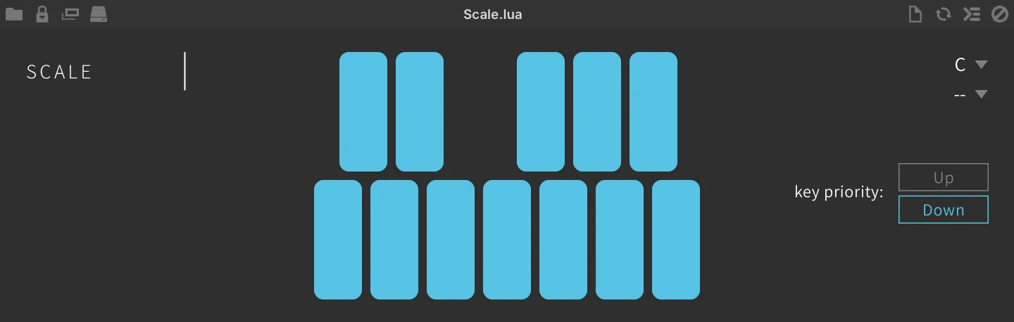
Snap notes of your MIDI input to a key and scale of your choice.
ROOT and SCALE set the root key and the scale from the drop-down menus.
NOTE buttons set the allowed notes individually.
KEY PRIORITY sets the priority of the incoming notes, lowest note or highest note played.
Tonal Harmonizer
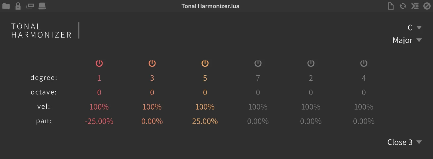
Create chords using scale degrees.
Sets the KEY and MODE of the scale using the drop-down menus.
POWER toggles each of the six harmony voices on/off.
For each note in your chord you can adjust the DEGREE (1–7), the transposition of the incoming note in scale degrees, OCTAVE (−2 to 2), VEL AMOUNT (0–200 %), which scales the incoming note velocity for that voice, and PAN (−100–100 %).
VOICING contains a number of useful presets, which also set the number of voices used.
Performance
Chord Strum

Plays back held notes sequentially at a user-defined speed.
Hold down any number of notes and press the Trigger Key to play them back sequentially at the Strum Speed. Notes will continue to be sustained until the Trigger Key is released.
TRIGGER OCTAVE sets the note octave of the Trigger Key (C), from −2 to 8. With the default setting of 4, holding C4 will trigger the strum playback.
STRUM SPEED sets the speed of the strum (inter-note) in milliseconds (1 to 200).
Legato

Crossfade the attack of legato-played keys for more realistic performance.
FADE sets the crossfade time in ms (10–100). RETRIGGER toggles retrigger mode on/off.
Modwheel Glissando

Use MIDI CC to strum pressed keys for a harp or guitar-like effect.
To use: hold down notes and move your keyboard’s modwheel or MIDI controller to strum the held notes across all octaves.
Select the controller number (0–127) by click-dragging or scrolling with your mouse wheel over the CONTROLLER field.
Clicking LEARN will set CONTROLLER to the next incoming MIDI CC number.
Portamento

MIDI glide with fade time.
FADE sets the portamento glide time in ms (1–500).
Portamento Stepped

MIDI step glide with fade time.
TIME sets the portamento glide time in ms (5–1000).
Strum
Play incoming MIDI notes like a guitar.
DIRECTION sets the pitch order in which notes will be played: up, down, up and down or random.
LAG sets the lag time for incoming notes.
HUMANIZE randomizes the trigger timing of incoming notes for a less-perfect sound.
VEL. SENS. (0–100 %) shortens the LAG time as velocity increases.
Strum Wheel

Harp-like strumming using MIDI CC.
NOTE LENGTH sets the note duration. LAG sets the lag time for incoming notes. MIDICC sets the MIDI CC number for control.
Physics
Balloons
The note repeater uses balloons bouncing to generate note repeats.
Click and drag the X in the center display to set the direction of the balloon launches by note trigger.
ACCELERATION sets the initial speed of the balloon.
JITTER adds variation (quiver) of the balloon’s movement.
ATTRACTION adds the attraction between the balloons.
GRAVITY sets the gravity (damping) of the balloon’s vertical movement.
Boids
The note repeater uses a flock of boids to generate note repeats.
The boids will generate the note when they cross the CENTER LINE of the display, and the line can be dragged to move the position.
RESTRICT sets the size of the space that boids fly around.
Sequencing
Cartesian Sequencer
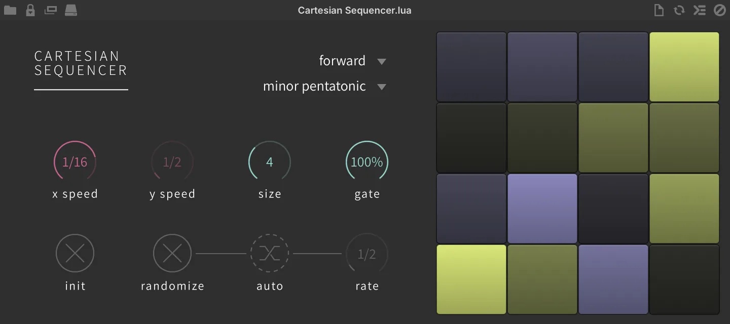
Cartesian sequencer with discrete X/Y movement and auto randomizer.
MODE sets the sequence direction from the drop-down menu.
-
FORWARD plays from upper left to right, then next row.
-
BACKWARD plays from upper right to left, then next row.
-
SPLIT DOUBLE TRIGGER plays from the upper left, depending on the X and Y speed settings.
INIT initializes the grid settings.
RANDOMIZE click to randomize the grid settings. AUTO enables automatic randomization at an interval set by RATE. RATE sets the auto randomize trigger interval.
SCALE sets the scale from a drop-down menu.
SEQUENCE GRID drag the grid to set the pitch-shift value of the grid.
X SPEED sets the playback speed in FORWARD and BACKWARD mode, and the X axis playback speed in SPLIT DOUBLE TRIGGER mode.
Y SPEED sets the Y axis playback speed in SPLIT DOUBLE TRIGGER mode.
SIZE sets the grid size. E.g. “4” is a 4x4 grid, “8” is an 8x8 grid.
GATE sets the gate duration of the next note played.
Chip Arp

Quickly create classic video game arpeggiations.
PATTERN sets the arp pattern from the drop-down menu. OCTAVE (−5 to 5) sets the octave shift up or down of the arpeggiation.
NOTE REPEAT (1–5) sets the number of the repeats.
GATE (1–100 %) sets the gate duration of the arp notes. LOOP enables loop arpeggiation. SPEED sets the rate of the arpeggio.
Drum Sequencer
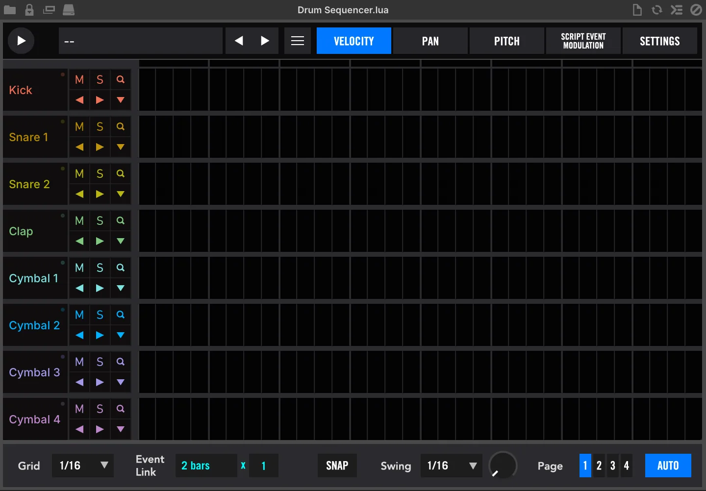
A full-featured 8-part, 8-bar X0X-style sequencer with velocity, pan, pitch, swing, external modulation control, preset load/save capability and more.
PLAY (top-left) plays or stops the sequence.
PATTERN PRESET contains a wide range of rhythmical patterns arranged by style and tempo.
≡ menu
CLEAR, resets the current configuration.
LOAD, loads a preset.
SAVE, saves the current sequence.
SAVE AS…, saves the current sequence as a new named preset.
SAVE ALL AS…, saves the current sequence and settings as a new named preset.
STATE A/B, switches between A/B states of the sequencer.
COPY A TO B/B TO A, copies the current sequencer state to the alternate slot.
COPY SEQUENCE PAGE, copies the current sequencer page (1–4) to the clipboard.
PASTE SEQUENCE PAGE, overwrites the visible/selected sequencer page from the clipboard.
LOCK MIDI MAP, locks the current parameter values on the Settings page (preserve key bindings while changing preset).
LOCK MUTES AND SOLOS, locks the current part mute and solo settings (preserve mix settings while changing preset).
Part controls are available in the left-most column, including: NAME and MIDI STATUS (●), MUTE (M), SOLO (S) and TRACK ZOOM (Q), SEQUENCE NUDGE LEFT / RIGHT (◀/▶) and FUNCTIONS (▼).
The main area of the interface is the GRID EDITOR, draw in values or double-click to input numerical values, right-click the grid and choose RESET ALL VALUES to clear it. At the top of the Grid Editor is a BEAT INDICATOR LED that lights up over the current beat.
Bottom Toolbar GRID sets the sequencer grid resolution.
EVENT LINK sets the interval of linked edits, with a setting of ‘1 bar’ every edit you make will be repeated in 1 bar intervals. SNAP enables grid snapping.
SWING DIVISION sets the swing interval. SWING knob sets the amount of swing. PAGE 1-4 changes the current sequence page — each page holds two of the eight bars (page 1 = bars 1–2, page 2 = bars 3–4, page 3 = bars 5–6, page 4 = bars 7–8). AUTO changes the visible sequencer page with the playhead.
Settings
Assignments and Naming PART NAMES double-click a part name to rename it ←COPY NAMES will name the parts according to the instrument names in the PART NOTE menu REFRESH to refresh the PART NOTE menu.
PART NOTE MENU set which incoming MIDI note will trigger the part.
Instrument Settings TIME is a bipolar trigger offset in ms (+/-200). GAIN adjusts the instrument Gain PAN adjusts the instrument Pan TUNE adjusts the instrument’s pitch.
Bottom Toolbar GENERATE MIDI creates a MIDI file from the current sequence, which can then be drag-and-dropped anywhere in your system or DAW via the DRAG ’N DROP button.
SEQUENCE TARGET NOTE select a note to use to gate playback of the sequence (use multiple Drum Sequencers with different target notes to create macro performances).
SLICE, when enabled, splits the sequence into its 8 bars and assigns their gated playback to eight chromatic notes starting at the Sequence Target Note, so each note starts playback from a different bar (perform the sequence like a chopped sample).
GLOBAL GAIN (−60–30 dB), PAN (±100 %) and TUNE (±36 st) offset the per-part values.
Euclidean Drum Sequencer
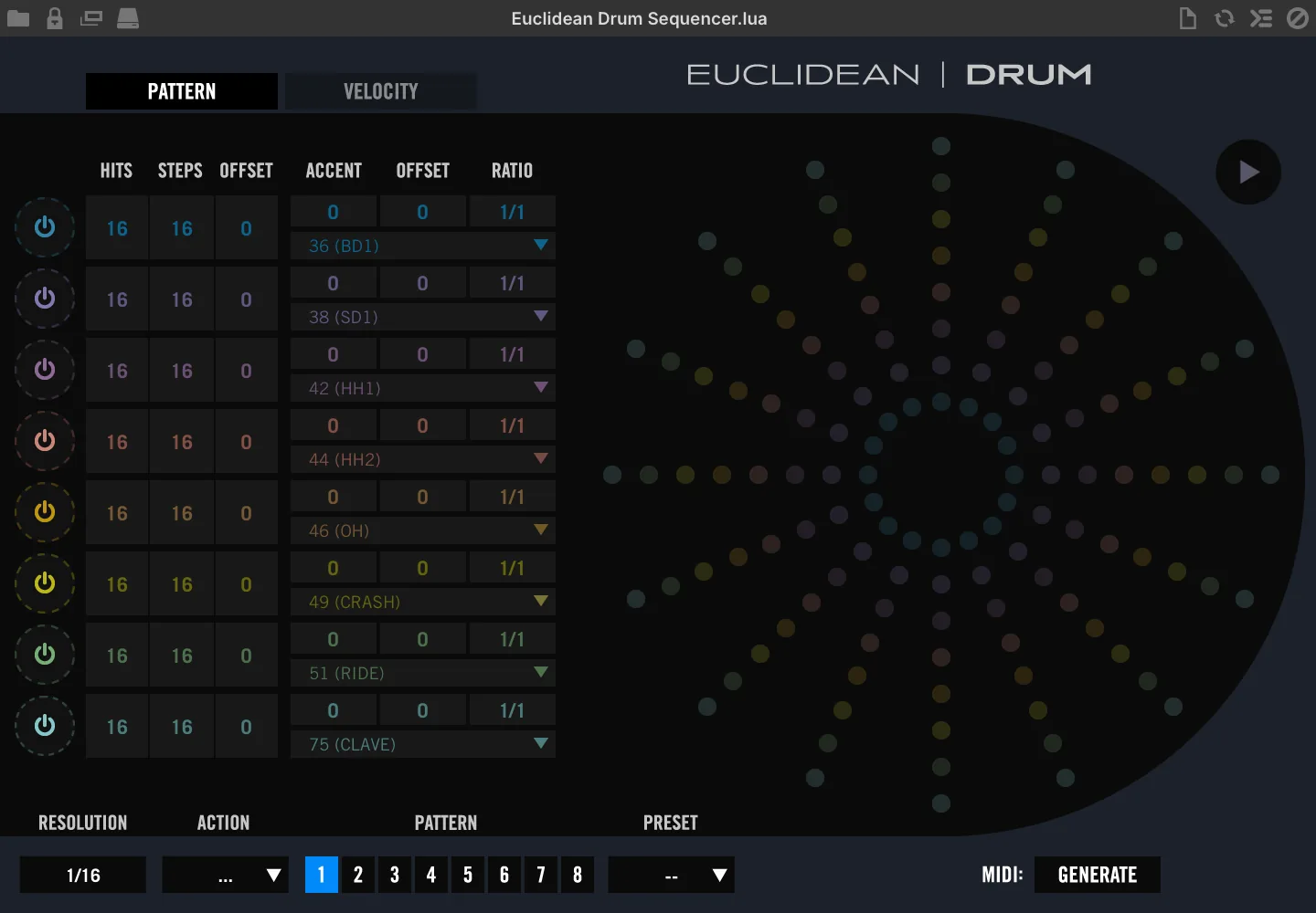
8-part sequencer based on Euclidean distribution oriented towards drum instruments.
PLAY (top-right) plays or stops the sequence.
Pattern Page Part Controls POWER toggles the part sequence on/off. HITS sets the number of steps that will trigger. STEPS sets the number of steps in the sequence. OFFSET offsets the sequence by a number of steps. ACCENT sets the step interval of accented triggers. ACCENT OFFSET offsets the accented triggers by a number of steps.
RATIO sets the part speed relative to the global resolution MIDI NOTE set MIDI note number that the part will trigger.
Euclidean Grid Displays the current sequencer state of all 8 parts. Active parts are indicated with a connecting circle; of those, dimmed and outlined nodes are not triggered, solid-filled nodes are triggered, solid-filled nodes with a white highlight are accented.
Velocity Page VELOCITY sets the MIDI note velocity per-part. ACCENT VELOCITY sets the MIDI note velocity of accented triggers per-part.
Bottom Toolbar RESOLUTION sets the global sequence speed. ACTION MENU allows you to copy and paste the current sequence using the 8 available pattern slots. PATTERN 1-8 changes the current configuration between 1 of 8 available pattern slots.
PRESET load a preset sequence into the currently selected pattern slot.
MIDI GENERATE creates a MIDI file of the visible sequence; the DRAG ’N DROP button then appears beside it, and from there the file can be dragged anywhere in your system or DAW. The button is hidden again as soon as the pattern is edited, so generate the file again after any change.
Euclidean Keys Sequencer
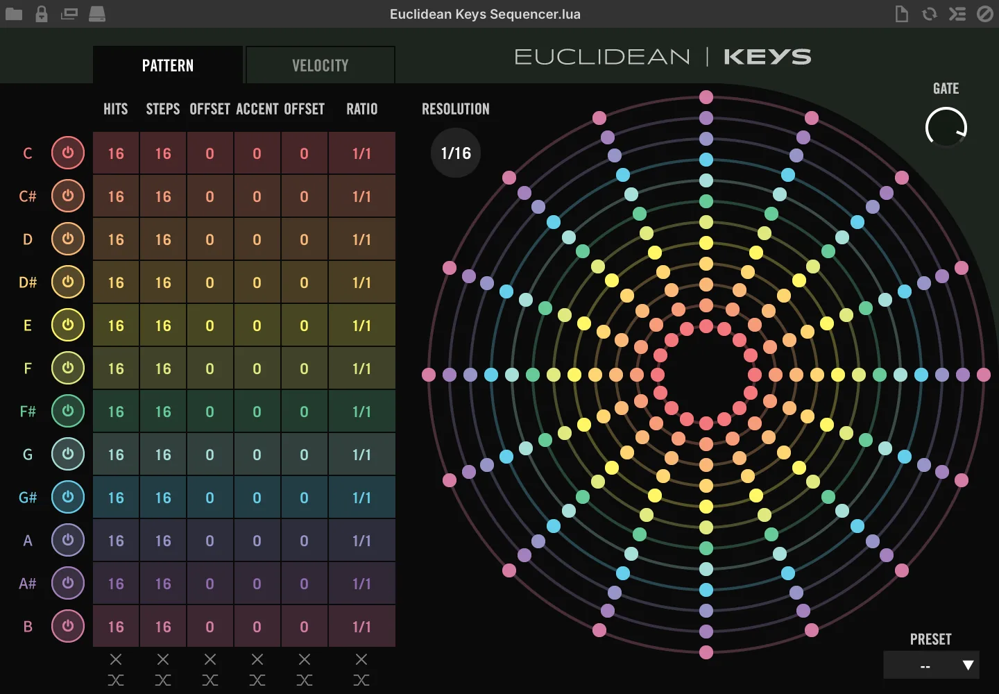
Generate discrete euclidean-based sequences for each key in the chromatic scale.
Pattern Page Note Controls POWER toggles the note’s sequence on/off. HITS sets the number of steps that will trigger. STEPS sets the number of steps in the sequence. OFFSET offsets the sequence by a number of steps. ACCENT sets the step interval of accented triggers. ACCENT OFFSET offsets the accented triggers by a number of steps.
Velocity Page VELOCITY sets the MIDI note velocity per note. ACCENT VELOCITY sets the MIDI note velocity of accented triggers per note.
GATE sets the global note gate length PRESET useful premade sequences (overwrites current sequencer configuration).
RATIO sets the note speed relative to the global resolution INIT click X switch at the bottom of each control to clear the settings.
RANDOMIZE click the switch at the bottom of each control to randomize the setting.
RESOLUTION sets the global resolution (sequence speed).
Euclidean Grid Displays the current sequencer state of all 12 notes — one ring per note of the chromatic scale, keyed by pitch class regardless of octave. Active notes are indicated with a connecting circle; of those, dimmed and outlined nodes are not triggered, solid-filled nodes are triggered, solid-filled nodes with a white highlight are accented.
Euclidean Tonal Sequencer
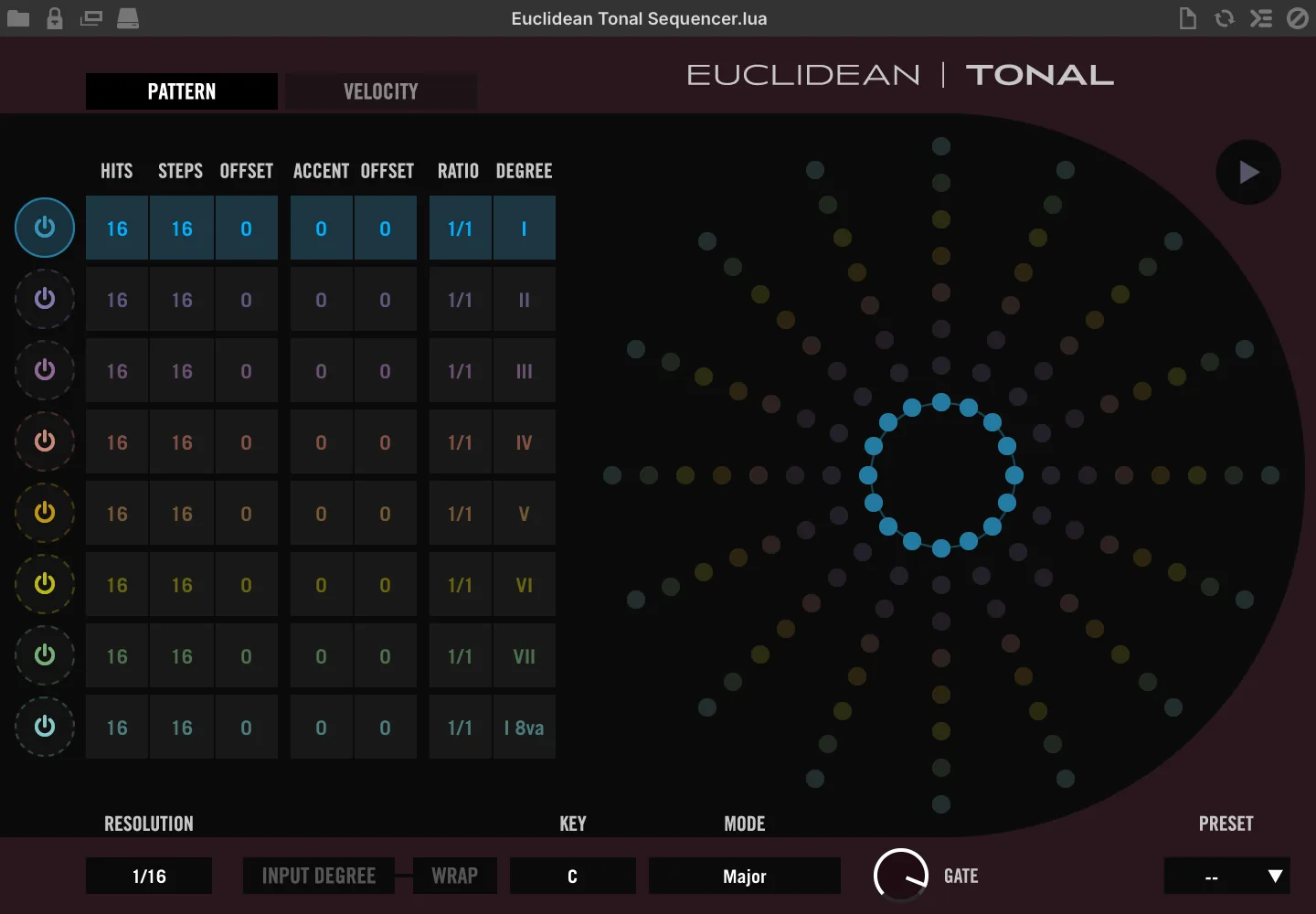
8-part sequencer based on euclidean distribution oriented towards tonal instruments.
PLAY (passive) will highlight when the sequencer is active.
Pattern Page Part Controls POWER toggles the part sequence on/off. HITS sets the number of steps that will trigger. STEPS sets the number of steps in the sequence. OFFSET offsets the sequence by a number of steps. ACCENT sets the step interval of accented triggers. ACCENT OFFSET offsets the accented triggers by a number of steps.
RATIO sets the part speed relative to the global resolution. DEGREE sets the degree relative to the master key and mode.
Velocity Page VELOCITY sets the MIDI note velocity per-part. ACCENT VELOCITY sets the MIDI note velocity of accented triggers per-part.
Bottom Toolbar RESOLUTION sets the global sequence speed INPUT DEGREE, when active, dynamically sets the sequence key to the lowest held note.
WARP while Input Degree is active, snaps pressed keys to tonal grid.
KEY sets the global key.
MODE sets the global scale.
GATE sets the global note gate length.
Euclidean Grid Displays the current sequencer state of all 8 parts. Active parts are indicated with a connecting circle; of those, dimmed and outlined nodes are not triggered, solid-filled nodes are triggered, solid-filled nodes with a white highlight are accented.
PRESET useful premade sequences (overwrites current sequencer configuration).
Gate Mod
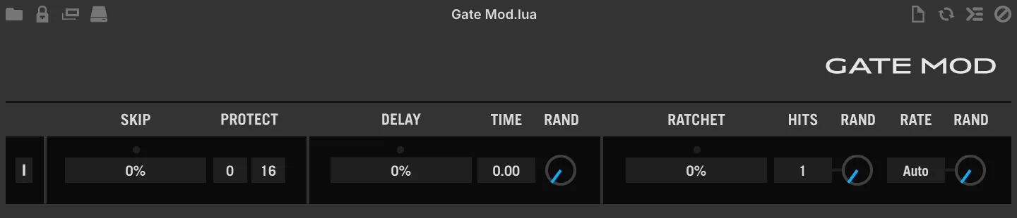
A probability-based multitool which can apply up to 3 functions per note event: Skip (mute), Delay (in ms), and Ratchet.
Gate Mod is a probability-based multitool including 3 processors: a skipper with beat protect, a delay, and a ratchetter. Processors are controlled by way of their probability sliders which are queried sequentially from left to right for every note received.
[I] click once to initialize the plug-in to the default state.
Probability Skipper
ACTIVITY LED a small circular indicator, lights up when the processor is triggered (and a note is skipped) SKIP PROBABILITY (0–100 %) sets the probability of skipping incoming note events.
PROTECT allows you to prevent notes from being skipped regardless of the probability value, based on their numerical order. This is useful for adding probability to sequences while protecting rhythmic patterns (like downbeats). For example, a setting of [1] / [4] will protect the first of every four notes, and a setting of [3] / [8] will protect the first three out of every eight notes received.
Probability Delay
ACTIVITY LED a small circular indicator, lights up when the processor is triggered (and a note is delayed) DELAY PROBABILITY (0–100 %) sets the probability of delaying incoming note events.
TIME sets the delay time in ms (0–1000) RAND randomizes [Time], 0= bypass, >0= randomized, greater values = longer potential time values (up to max).
Probability Ratchetter
ACTIVITY LED a small circular indicator, lights up when the processor is triggered (and a note is ratcheted) RATCHET PROBABILITY (0–100 %) sets the probability of ratcheting incoming note events.
HITS (1–8) sets the number of times the note repeats; its RAND (0–100 %) adds a random number of extra hits, up to 8. RATE sets the repeat length, Auto or 1/2 to 1/32 including dotted and triplet values; Auto divides a 1/16 note by the number of hits. Its RAND (0–100 %) randomly shortens the rate, down to 1/32 at most.
Gate Mod Bernoulli
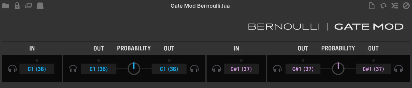
A 2-channel probability-based note router, with note learn.
A note-focused Bernoulli gate. Assign one source note (IN) and two destinations (OUT), then control the likelihood of which destination gets triggered with the probability knob. Useful for creative applications and variable drum patterns. Includes two discrete channels (blue and purple) with identical functionality.
IN
[ NOTE LEARN] click to activate Note Learn mode, the channel will bind to the next MIDI note received.
ACTIVITY LED a small circular indicator, lights up when the assigned note is detected.
[NOTE IN] click-drag to change the note IN assignment of the channel, double-click for numeric entry.
OUT
[ NOTE LEARN A/B] click to activate Note Learn mode, the channel will bind to the next MIDI note received.
ACTIVITY LED A/B a small circular indicator, lights up when the assigned note is triggered.
A/B PROBABILITY sets the probability of IN notes going to OUT A or OUT B, where value 0%= all note INs go to Out A, and 100%= all note INs go to Out B.
Gate Mod Poly
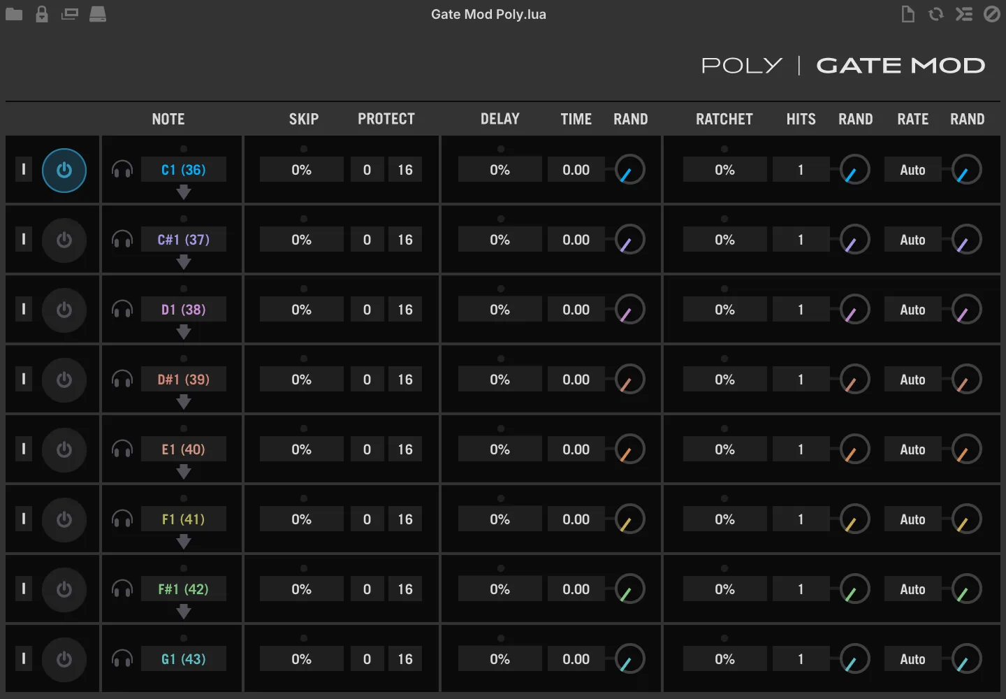
An 8-channel, note-specific variant of the Gate Mod script processor.
Gate Mod Poly is an 8-channel variant of Gate Mod, with per-channel bypass, note learn, and auto-assign. It’s an ideal pairing for the Drum Sequencer or Euclidean Drum Sequencer scripts, or in any situation where you need note-specific control of Gate Mod to add non-repeating variability and interest to a sequence.
The following section deals only with the unique controls of the poly version, for use of Gate Mod processors see: Event Processors › Script Processor › Gate Mod.
[ ↓ AUTO ASSIGN] assigns notes to all following channels, sequentially from the current note up, for example clicking [Auto Assign] on channel 1 with an assignment of C3 will set the remaining channels to C#3, D3, D#3, E3, F3, F#3, and G3. Combine with [Note Learn] for setup in 3 clicks.
[ POWER] click to enable/disable the channel.
[ NOTE LEARN] click to activate Note Learn mode, the channel will bind to the next MIDI note received.
[NOTE] click-drag to change the note assignment of the channel, double-click for numeric entry.
MIDI CC LFO
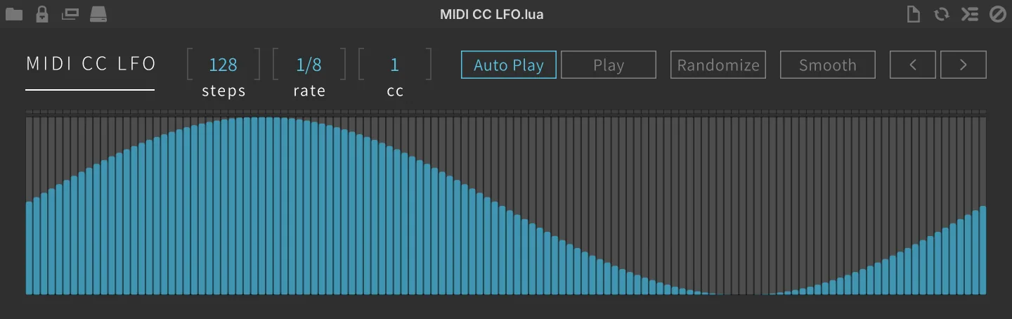
A multi-step MIDI CC modulator.
STEPS sets the number of steps to be played.
RATE sets the step length.
MIDI CC sets the target MIDI CC number.
AUTO PLAY enables retrigger mode.
PLAY enables free running mode.
SEQUENCER click to change values, double-click for numerical entry, or click-drag across the sequencer to draw custom modulation shapes.
RANDOMIZE sets every step to a random value.
SMOOTH click to apply a slight smoothing to the shape after hand-drawing.
The < and > buttons rotate all step values one step to the left or right, wrapping around the end of the sequence.
Motion Grid
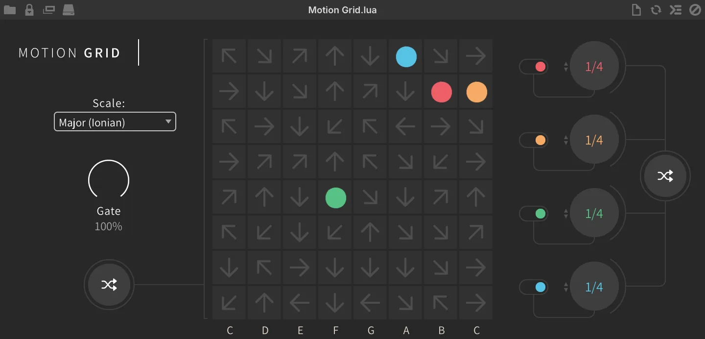
A logic-based grid sequencer driven by directional nodes.
SCALE sets the scale of the arpeggiation. GATE sets the gate amount (limitation of the note length). Click the RANDOM button to randomize grid node direction and start points.
Click the corner or side of each grid to set the moving DIRECTION.
Settings for each voice: ON/OFF switches voices on or off. RATE sets the speed of the voice movement. Click the RANDOM button to randomize the voice speed.
Node Arp
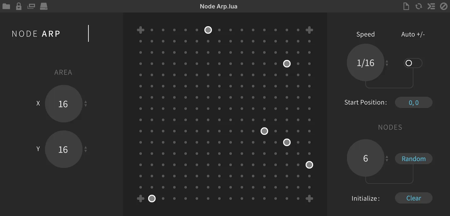
A logic-based grid sequencer driven by active/passive nodes.
AREA sets the matrix size, X and Y individually.
Click dots in the matrix to ADD or REMOVE the NODES manually.
SPEED sets the speed of the playheads, from 1/1 down to 1/32. RDM SPEED lets the read head halve, double or keep its speed each time it crosses a node.
The start-position button toggles between SAME, where every playhead starts from the node closest to the top-left corner of the matrix, and RANDOM, which picks a start node at random.
NODES sets the number of nodes by random generation. Click the RANDOM button to randomly generate nodes. Click the CLEAR button to remove all nodes from the matrix.
Ostinato Arp
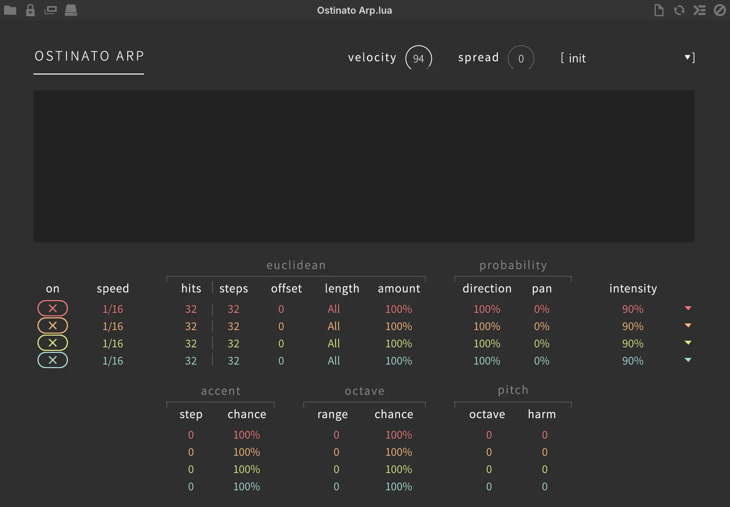
Four arpeggiators in parallel creating rhythmic and hypnotizing patterns.
Global Controls
VELOCITY sets the note velocity.
SPREAD sets the note spread.
[MENU] to choose the preset from the list.
Probability
DIRECTION sets the direction chance, -100% = down, 0% = up-down, 100% = up.
PAN sets the randomness of the pan position.
Accent
STEP sets the accent step. CHANCE sets the amount of the accent pattern probability.
Per Arpeggiator Controls
ON sets the arpeggiator enable (x) or disable (+).
SPEED sets the rate of the arpeggiator.
Euclidean
HITS sets the number of steps that will trigger. STEPS sets the number of steps in the sequence. OFFSET offsets the sequence by a number of steps. LENGTH sets the pattern length from 1 to 16 or all notes. AMOUNT sets the amount of the euclidean pattern probability.
Octave
RANGE sets the octave range of the arpeggio pattern. CHANCE sets the amount of the octave range shift probability.
Pitch
OCTAVE shifts the octave up to +/- 2 octaves. HARM sets the amount of the harmonization.
INTENSITY sets the note intensity of the arpeggio.
Each arpeggiator’s ▼ menu holds three commands:
-
INIT: reset that arpeggiator’s settings to their defaults.
-
COPY: copy that arpeggiator’s settings.
-
PASTE: paste the copied settings into that arpeggiator.
Polyphonic Sequencer

Polyphonic sequencer with one sequencer running per key pressed with volume, pan, pitch and timing support.
SCALE ROOT sets the root key of the sequence. SCALE sets the scale of the sequence phrase.
REPEATS sets the number of steps to be played (1–64).
TIME sets the step length, from 4 bars to 1/32 note.
LENGTH (0–150 %) scales the note length of every step.
Sequencer Pages TUNE sets the pitch offset in semitones (+/-24). VELOCITY sets the note velocity multiplier (0–200 %). PAN sets the absolute pan value (L/R).
POLY AFTERTOUCH sets the aftertouch volume amount (0–127). REPEAT sets the note repeat amount (1–8). LENGTH sets the note gate length (0–100 %).
PRESET a selection of useful sequencer presets.
ONE SHOT disables looped sequence playback.
RANDOM START enables random start position of the sequence.
Probability Arp
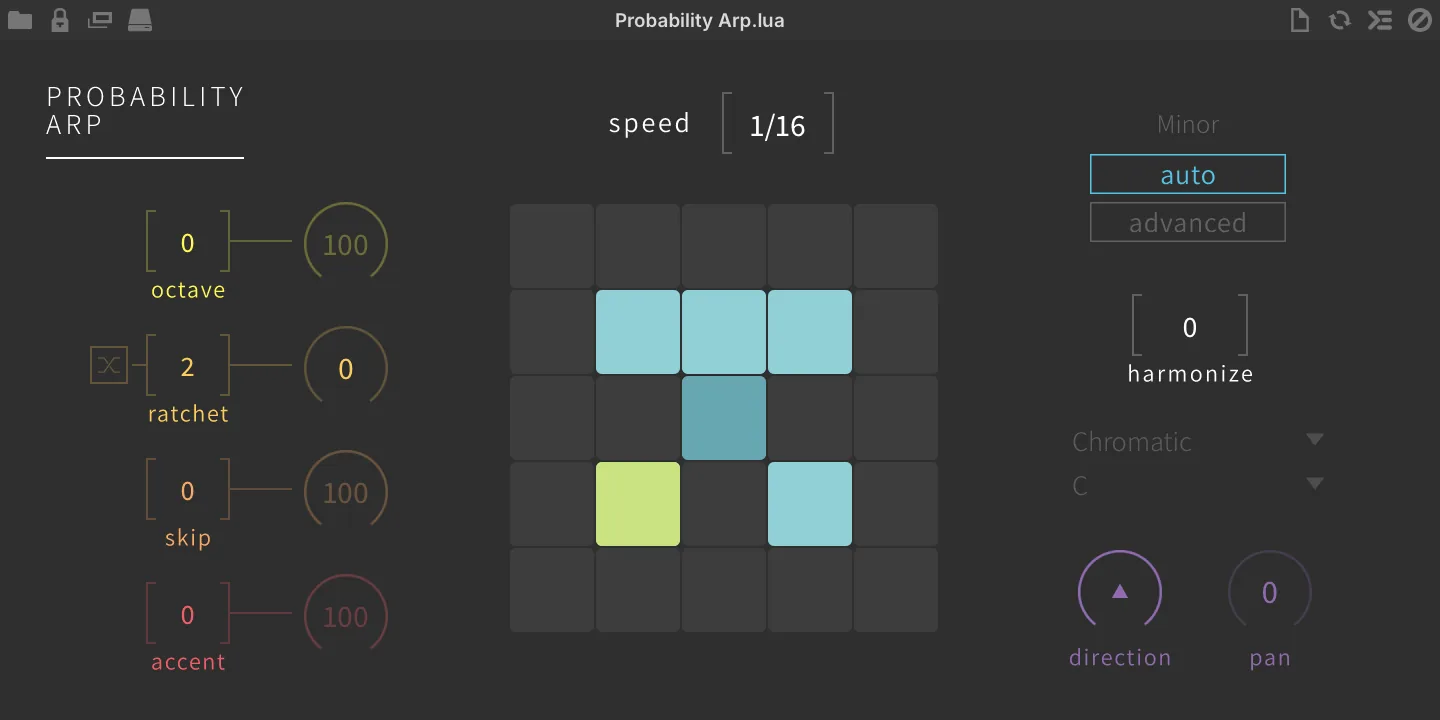
Arp with chance-based octave, ratchet, skip, accent, direction, pan, and harmonization.
SPEED sets the sequence speed.
Left Controls
OCTAVE sets the octave range with probability amount. RATCHET sets the count of ratcheting incoming note events, randomize with probability amount.
SKIP sets the count of skipping incoming note events with probability amount.
ACCENT sets the accent count with probability amount.
Right Controls
AUTO / ADVANCED MODE switch between automatic chord/scale detection or advanced (manual) mode.
HARMONIZE sets the probability of the harmonization.
MODE sets the global scale. KEY sets the global key.
DIRECTION randomizes the arp direction. PAN randomizes the pan setting.
Rain Sequencer
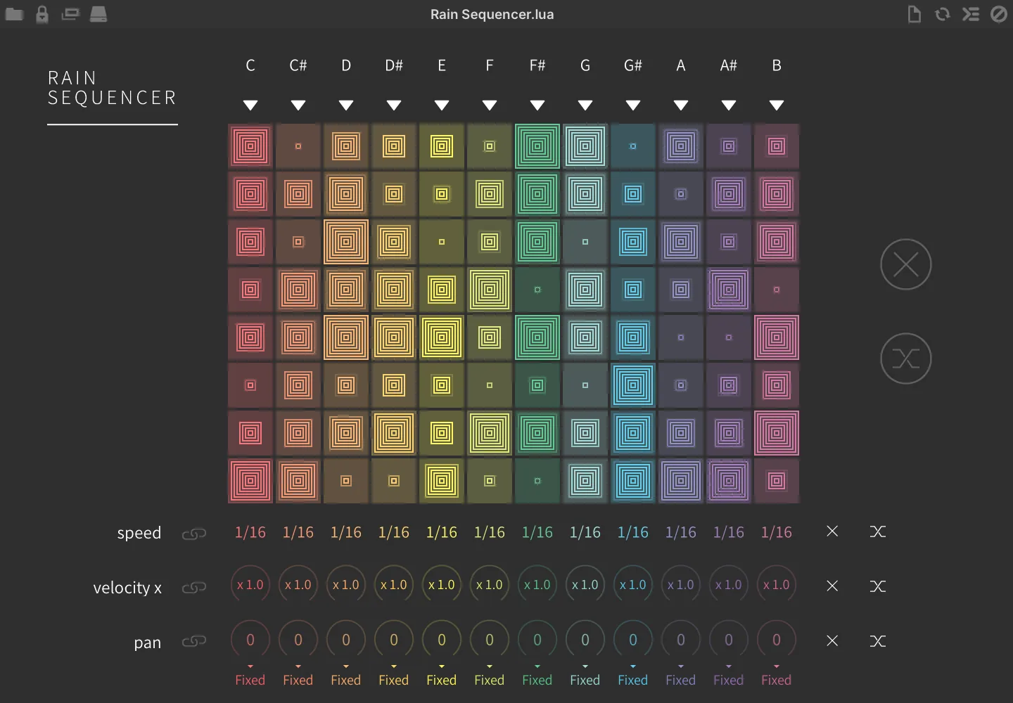
12 note-based vertical sequencers with discrete speed, velocity, and pan modifiers.
Each row carries a MENU ▼ with the following commands:
-
INIT initializes the values of the line.
-
CLEAR clears the values of the line.
-
RANDOMIZE randomizes the values of the line.
-
COPY TO copies the values of the row and pastes to the line of your choice.
-
TEMPLATES applies a template pattern to the line.
STEP EDITORS drag to set the velocity of the step INIT (X) initializes the values of all row steps. RANDOMIZE randomizes the values of all row steps.
SPEED sets the step speed per note. VELOCITY sets the step velocity multiply amount per note. PAN sets the MIDI panning mode per note.
-
FIXED outputs the fixed stereo position set by the note’s dial.
-
ALT alternates the pan left and right with each keypress; the dial sets the depth of the alternation.
-
RAND outputs a random pan position with each keypress; the dial sets the depth of the randomization.
-
NONE has no panning effect
LINK allows you to edit all rows simultaneously.
INIT (X) initializes the parameter values for all notes at once RANDOMIZE randomizes the parameter values for all notes at once.
Slice Remixer
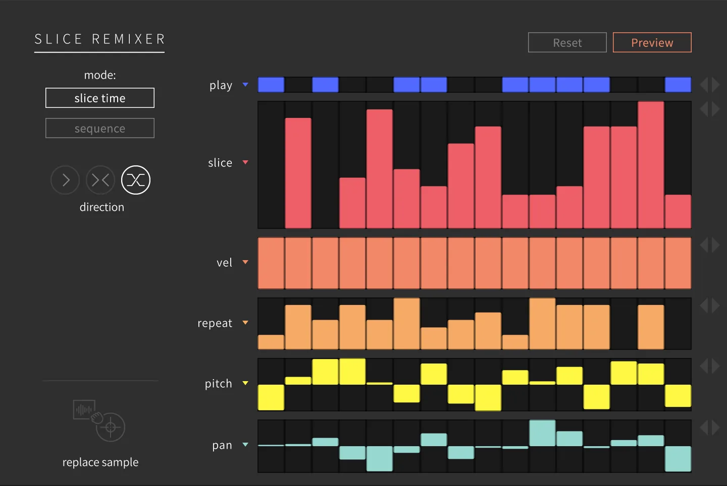
In conjunction with the Slice sample oscillator, quickly remix sliced loops to create new patterns.
The sample loads into the Slice oscillator, the slices will be added to the Slice Remixer and the keys will be mapped from C3/note#60 for each slice.
Use C2 / note#48 to trigger the Slice Remixer.
RESET click to reset the Slice oscillator. This is useful when replacing the sample in the oscillator.
VELOCITY sets the slice velocity. Click the ▼ button to initialize or randomize the steps, and use the ◀▶ buttons to shift the steps left or right.
PREVIEW enables preview when tweaking the Slice IDs.
MODE sets which slice timing mode to use, SLICE TIME uses slice timing from the sample, SEQUENCE uses fixed timing set by RATE and STEPS.
DIRECTION sets playback direction: FORWARD, PING PONG (alternate forward and backward) and RANDOM.
Drag sample to REPLACE SAMPLE icon to swap the sample for slicing.
PLAY sets the step to play or mute. Click the ▼ button to initialize or randomize the steps, and use the ◀▶ buttons to shift the steps left or right.
REPEAT sets the number of times the step should repeat. Click the ▼ button to initialize or randomize the steps, and use the ◀▶ buttons to shift the steps left or right.
PITCH sets the per-step semitone offset (−24 to 24). Click the ▼ button to initialize or randomize the steps, and use the ◀▶ buttons to shift the steps left or right.
PAN sets the per-step MIDI panning. Click the ▼ button to initialize or randomize the steps, and use the ◀▶ buttons to shift the steps left or right.
SLICE ID sets the slice to use for the steps. Click the ▼ button to initialize or randomize the steps, and use the ◀▶ buttons to shift the steps left or right.
Snowflakes
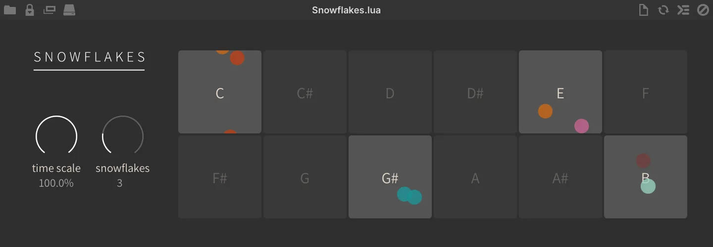
A 12-note based sequence modifier turning sustained notes into fluttery staccato.
TIME SCALE sets the speed of event generation (particles falling).
SNOWFLAKES sets the number of particles in each note display (note generation).
Step Arp

A full-featured step-based arpeggiator with type, ratio, velocity, gate, MIDI CC, mode, repeat, pan, octave, pitch and probability per-step, with independent length control for each channel.
STEPS sets the number of steps for the sequence. RESOLUTION sets the step length (1/32 to 1/2 note, including dotted and triplet values) based on the BPM of the host.
GATE sets the gate amount (1–100 %).
OCTAVE sets the octave range of the sequence (−3 to +3) PRESET select a factory preset configuration PRESET ▶ select the next preset PRESET ◀ select the previous preset.
Step Parameters
GLOBALS (CHANNEL HEADERS)
[I] initialize the values of the row.
[R] randomize the values of the row [-] sets the step length of the row independently from the main step length, allowing for varied and polyrhythmic sequences.
VELOCITY sets the per-step velocity amount (1–127). GATE sets the per-step gate amount (1–100 %).
MIDI CC selects which controller (CC 1–4) the row edits by clicking in the header row, then sets the modulation value per-step (0–127). ARP TYPE sets the arpeggiator sequence shape. REPEAT sets the number of times the step should repeat (2–8). PAN sets the per-step MIDI panning.
OCTAVE sets the per-step octave (−2 to 2) relative to the global octave setting.
PITCH sets the per-step semitone offset (−24 to 24). PROBABILITY sets the per-step probability amount (0–100 %) RESET toggle on to activate, when a RESET step is played the ARP TYPE sequence resets to the first note.
STEP TYPE sets the step function: Empty= does nothing, Note= plays a note, Repeat= repeats the last note, Glide= sustains the last note. RATIO sets step length relative to the main resolution, clicking in the channel header allows you to set all steps at once.
Step Line
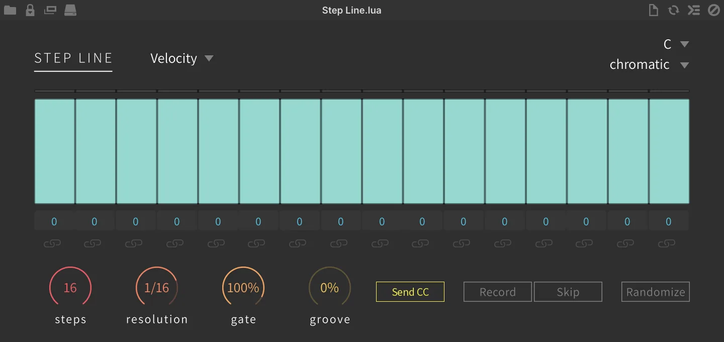
Sequencer Pages Step Line
VELOCITY sets the per-step velocity level. PITCH sets the per-step pitch offset (+/-48 semitones). LENGTH sets the per-step gate amount. CC1/2 sets the per-step modulation level to send on CC1/2.
The ▼ menu beside the module name chooses which page the grid edits: VELOCITY, PITCH, LENGTH, CC 1, or CC 2.
STEPS sets the number of steps to be played (1–16). RESOLUTION sets the step length (1/32 to 1/2 note, including dotted and triplet values). GATE sets the gate amount (0–110 %). GROOVE sets the groove amount (0–50 %).
Bassline-oriented sequencer.
SCALE ROOT sets the root key of the sequence. SCALE sets the scale of the sequence phrase.
RECORD switch enables phrase record mode - use to quickly program pitch sequences.
SKIP (in RECORD mode) skips over the next step.
SEND CC (enabled by default) sends the per-step CC 1 and CC 2 values; disable it to play the sequence without any MIDI CC output.
Sequencer PLAYBACK INDICATORS (passive) display the current step being played back.
RANDOMIZE randomizes all step values.
SEQUENCER click to change value, double-click for numerical entry, click-drag to create custom modulation shapes.
PITCH VALUE displays the current step pitch value (double-click for numerical entry).
LINK (Tie) combines adjacent steps into a single step, using their combined duration and value.
Warp Sequencer
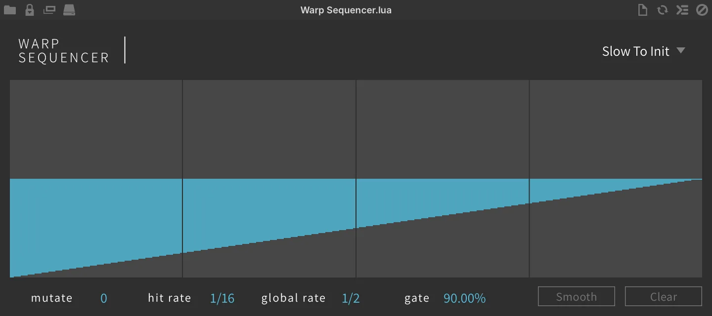
Generate chord-based sequences with hand-drawn speed curve.
PRESETS ▼ select a sequence preset from the menu.
SEQUENCE EDITOR draw a sequence by click-and-drag.
MUTATE sets the mutation rate of the sequence.
HIT RATE sets the sequence hit rate.
GLOBAL RATE sets the global speed of the sequence.
GATE sets the gate amount.
SMOOTH click to apply a slight smoothing to the sequence shape after hand-drawing.
CLEAR clear the sequence form.
Waterfall

Arpeggios with a twist.
MODE sets the arpeggio mode up or down.
TIME sets the interval of the arpeggio in ms or musical interval with SYNC on.
OCTAVE sets the octave range up to 5. LOOP enables loop arpeggiation. REPEAT sets the number of note repeats up to 5.
Wave Sequencer
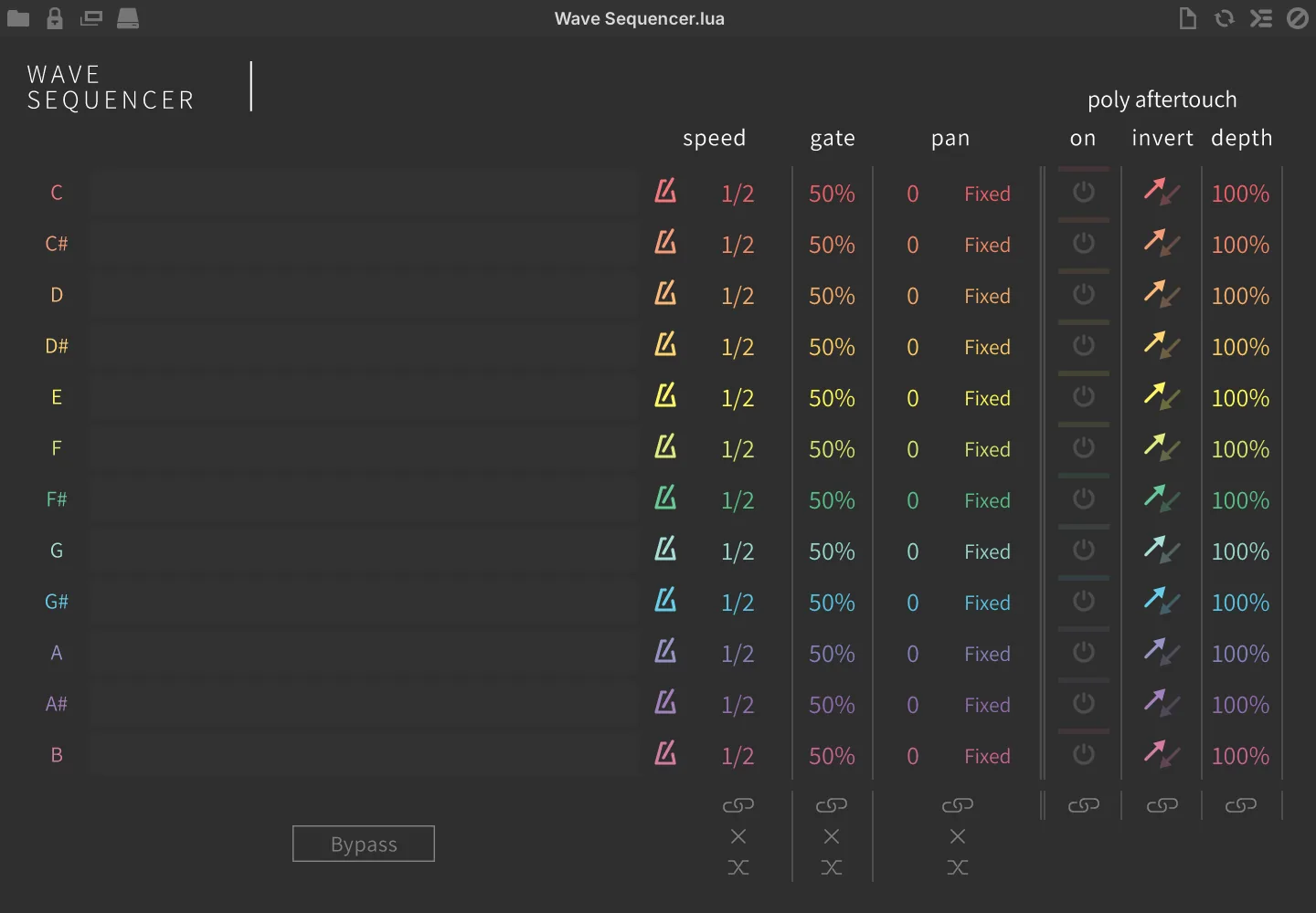
12 note-based clocked event generators with poly aftertouch output.
SPEED sets the step speed in Hz or note duration (sync on) per note.
GATE sets the gate amount per note.
PAN sets the MIDI panning mode per note.
-
FIXED outputs the fixed stereo position set by the note’s dial.
-
ALT alternates the pan left and right with each keypress; the dial sets the depth of the alternation.
-
RAND outputs a random pan position with each keypress; the dial sets the depth of the randomization.
-
NONE has no panning effect
LINK lets you adjust values for each note simultaneously.
INIT (X) initializes the parameter values for all notes at once.
RANDOMIZE randomizes the parameter values for all notes at once.
BYPASS disables the sequence.
Poly Aftertouch
ON enables poly aftertouch per note.
INVERT switches the aftertouch modulation direction, normal or inverted per note.
DEPTH sets the aftertouch modulation depth per note.
LINK lets you adjust values for each note simultaneously.
Utilities
Invert Pitch

Invert the pitch of the incoming MIDI note.
All incoming notes will be transposed by inversion relative to the CENTER PITCH MIDI note number.
For example, setting the Center Pitch to C3 and playing C2 will result in C4.
Limit Range

A range limiter of incoming MIDI notes.
MODE to deal with the notes out of the limiting range:
-
OFF: mute the notes out of the range setting.
-
NEAREST OCTAVE: the notes out of the range will be shifted to the nearest octave in the range.
-
REPEAT RANGE: the limiting range will be duplicated across the whole key range.
-
LIMIT: all notes out of the range will be transposed to the lowest note and highest note of the range.
-
SINGLE: limit to a single note.
MIN sets the lowest note of the range. MAX sets the highest note of the range.
Mapper
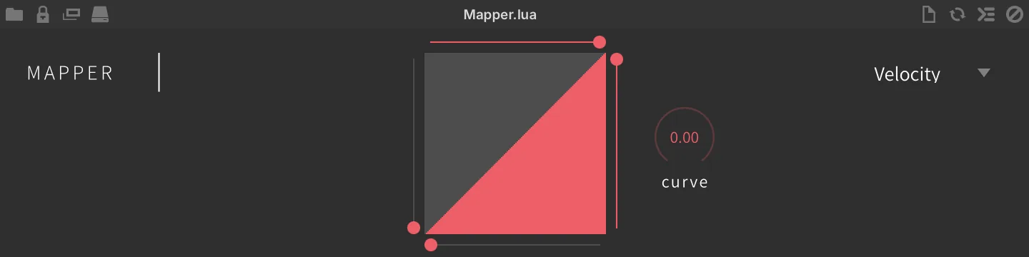
A MIDI signal range re-mapper.
TARGET sets the incoming MIDI message to re-map Click-drag the DISPLAY to draw the desired curve shape. MINIMUM SLIDER (left side of the display) sets the minimum output value.
MAXIMUM SLIDER (right side) sets the maximum output value. MINIMUM X SLIDER (bottom) sets the lowest input value that is re-mapped, and MAXIMUM X SLIDER (top) the highest. CURVE knob sets the re-mapping curve.
MIDI CC Filter

Filter the incoming MIDI CC.
MIDI CC sets the incoming MIDI CC message number to filter.
MIDI CC Redirect

A MIDI CC message re-mapper.
SOURCE sets the incoming MIDI CC message number. TARGET sets the output MIDI CC message number.
MIDI CC Smoother

Slew, or smooth out MIDI CC values over time.
MIDI CC (1–127) sets the incoming MIDI CC message number. SMOOTH TIME (0–3 s) sets the smooth time of the message.
MIDI Delay

Delay the incoming MIDI data.
MIDI DELAY sets the delay time of the incoming MIDI messages in ms (0–200).
MIDI Monitor
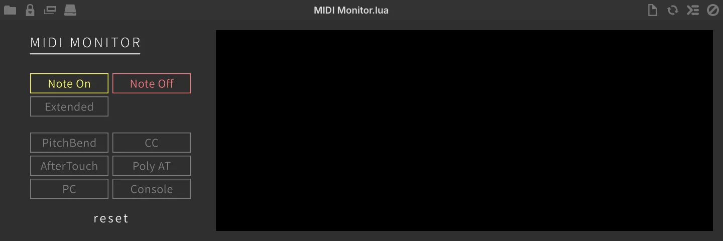
Click the message buttons on the left to control which event types are shown in the output display: Note On, Note Off, PitchBend, CC, AfterTouch, Poly AT and PC. Two further buttons are not filters — Extended appends Volume, Pan, Tune and Id details to the Note On and Note Off lines, and Console mirrors the log to Falcon’s script console. The display holds the ten most recent events, color-coded by type, and reset clears it.
MIDI input monitor with event type filters, useful for debugging.
Click the RESET button to reset the display.
MIDI Record

Record events to a MIDI file with drag-and-drop support.
Hit the RECORD button to start recording MIDI events.
The BUFFER indicator will show the length (beats) and number of events that have been recorded.
PLAY will play back the recording.
CLEAR (X) will clear the recording.
Use the DRAG & DROP to export the recordings as a MIDI file, try dragging to a DAW MIDI track or your desktop.
MPE
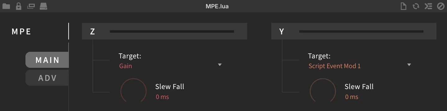
Helper for MPE controllers.
Main
The module has two pages, selected with the MAIN and ADV buttons; Main is shown when the module is added.
The Z (PRESSURE) and Y (TIMBRE) sections each carry a read-only meter showing the incoming value for that axis, together with the controls that route it. Following the usual MPE conventions, Z reads channel pressure (channel aftertouch) and Y reads CC74. Choose the control target (modulation source) from the TARGET: menu, and use SLEW FALL (0–3 s, displayed in ms below one second) to set how quickly Falcon follows the control changes (release smooth time). Slew Fall is disabled when its Target is set to PolyAT.
Adv
X (PITCH) routes the X axis message of the MPE controller, which reads pitch bend. Choose the control target from TARGET: menu. RANGE sets bipolar pitch bend range in semitones (0–48, 48 by default), usually set to 24 or 48.
Advanced Settings
AUTO RELEASE enables auto release Z axis on note-off. GAIN MAP sets the gain mapping curves (20 dB, z², Linear). This is an automatic gain remapping when Z axis is used to control Gain. INIT Z sets the initial value of the Z axis, used until the controller sends one.
GLOBAL CHANNEL sets the global MIDI channel of the MPE controller (1–16).
Pgm Change Switcher

Use MIDI Program change message as a switch to route events to different channels.
INCOMING sets the incoming MIDI channel of the program change message.
DESTINATION sets the output MIDI channel of the program change message.
OFFSET transpose the MIDI program change message.
REMAP MIDI CHANNELS remaps MIDI channels incrementally from A1 onwards.
Transpose

A MIDI transposer.
TRANSPOSE sets the transposition of incoming MIDI notes in semitones.
Velocity Test
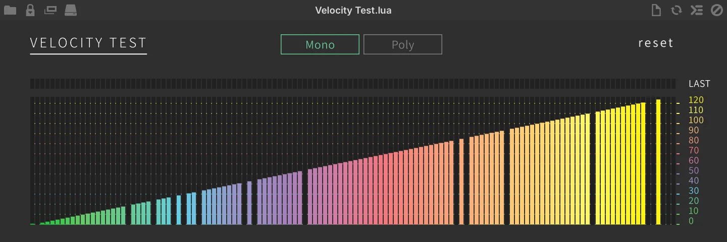
Note velocity monitor with mono and poly modes, useful for debugging.
MONO / POLY switch between MONO or POLY modes. RESET resets the display.
Modulators
Modulators
Modulation generators can be instanced at any level in a patch, allowing them to control nearly any parameter, be it on an oscillator, effect or even on another modulator. This system allows you to paint motion into your sounds almost effortlessly, from subtle variation over time to complex on-demand sequences.
Control signals that move parameter values; they never carry audio or MIDI.

An envelope with attack, hold and decay stages, simpler than a full DAHDSR. It suits simple shapes, like the envelopes of some classic synths.
Read more ↓
An attack, decay, sustain and release envelope whose decay behaves like that of classic analog envelopes. It gives a more vintage feel than a precise digital ADSR.
Read more ↓
The simplest envelope, with an attack and a decay stage only. It is often used for percussive sounds that need no sustain or release.
Read more ↓
A classic envelope with delay, attack, hold, decay, sustain and release stages: an ADSR with an extra delay before the attack and a hold between attack and decay. It suits amplitude and filter envelopes that need full control.
Read more ↓
An envelope traced from an audio file: it follows the level, brightness or pitch contour of a recording and plays it back as a modulation source. It gives a sound the movement of a real performance, with speed control and a loop region that turns a one-shot gesture into a sustained movement.
Read more ↓
A random walk generator. It simulates natural drift, such as the wandering pitch or amplitude of a sustained note.
Read more ↓
A random modulator that generates smooth streams of random values, shaped by rate, depth and trigger options. It suits organic, evolving movement, from subtle shifts to flowing textures.
Read more ↓
A low frequency oscillator that generates a cyclical modulation signal below the audible range, with classic and additional waveforms. It suits vibrato, tremolo, filter sweeps and other periodic movement.
Read more ↓
A control that appears on the Info tab and moves every parameter assigned to it. It puts a program’s important settings on its front panel, one knob per parameter or one knob for many.
Read more ↓
An envelope of up to 128 points with adjustable curves, drawn by hand or built from dropped MIDI or audio files, which can be looped. It suits long, expressive modulation sequences and looped, LFO-like shapes.
Read more ↓
An LFO that mixes sine, triangle, square, saw and random contributions. It suits complex cyclic shapes that a single waveform cannot give.
Read more ↓
An LFO whose waveform is built from parametric controls such as Shape, Symmetry, Pulse Width and Swing. Since these controls can themselves move in real time, it suits cyclic modulation whose shape evolves.
Read more ↓
A modulation source driven by a Script Processor: a script sends target values to it with sendScriptModulation, and it ramps to each value it receives. It lets a script drive any parameter that can be modulated.

A random LFO whose values move smoothly from one to the next. It suits gentle, unpredictable movement.
Read more ↓
A programmable step sequencer of up to 128 steps, tempo-synced to musical divisions or running at a free rate. It suits rhythmic patterns such as gating, and with spline interpolation, smooth LFO-like shapes.
Read more ↓
A polyphonic step sequencer of up to 16 steps that generates an independent modulation signal for each voice. It suits animated pads, evolving sweeps and rhythmic motion.
Read more ↓AHD
The AHD envelope (attack, hold, and decay) is a simpler envelope than a full DAHDSR envelope, similar to envelopes found on some classic synths.
The ATTACK (0–10 s), HOLD (0–10 s), and DECAY (0–30 s) values can be set by the sliders, or by adjusting the points in the envelope editor. Additionally, the curve of the Attack and Decay ramps can be changed by dragging the line itself. For more details on editing the envelope graphically in the envelope editor, see: DAHDSR › Envelope Editor.
To choose if and how velocity will affect the envelope, use the VEL. AMOUNT (0–100 %) and VEL. SENS (±100 %) controls, as described in DAHDSR › Vel. Amount and Vel. Sens.
Analog ADSR
The Analog ADSR envelope (attack, decay, sustain, and release) is an envelope with decay characteristics similar to classic analog envelopes, providing a more vintage feel than a precise digital ADSR.
The ATTACK (0.0001–10 s), DECAY (0.0001–10 s), SUSTAIN (0–100 %), and RELEASE (0.0001–10 s) controls set the basic envelope shape, and DYNAMIC (0–40 dB) controls the amount of the output range controlled by the trigger velocity.
PUNCH (0–100 %) drives the attack beyond its normal ceiling: the attack aims at a higher target and only hands over to the decay once it has reached that overshoot, while the output itself remains clipped to full level. The audible result is a flat plateau at the top of the envelope, covering the end of the attack and the beginning of the decay, which grows longer as Punch is raised.
Two modes alter how the envelope is triggered and processed. If the ATTACK/DECAY mode is set to AD, only the attack and decay phases of the envelope are used; sustain and release will have no effect. When set to ADSR, all phases of the envelope can be configured. The Analog ADSR’s TRIGGER MODE offers the Retrigger and Legato modes described in LFO › Trigger mode.
The manual TRIGGER button allows for the envelope to be triggered on demand, and can be controlled remotely via automation or modulation.
You can choose how velocity affects the envelope’s attack and decay with the VELATTACK (±100 %) and VELDECAY (±100 %) controls. Additionally, the VELOCITY button inverts the velocity feeding those two controls, so that soft notes behave like hard ones. It does not affect DYNAMIC, which always follows the played velocity.
Likewise, you can choose how key follow affects the envelope’s attack and decay with the KEYATTACK (±200 %) and KEYDECAY (±200 %) controls.
Attack Decay
The Attack Decay envelope is the simplest modulation envelope provided. An Attack Decay envelope is often used for percussive sounds that don’t need a sustain or release.
DECAY (0.001–10 s) is set to a time value, and ATTACK (0–100 %) is set as a percentage of the Decay time. The attack is clamped internally to between 1 % and 99 % of the decay, so the two phases never collapse into one.
DAHDSR
The DAHDSR envelope (delay, attack, hold, decay, sustain, and release) is a classic synthesis envelope style. It is an extension of the common ADSR envelope, with an additional delay phase at the beginning and a hold phase between attack and decay.
The DELAY (0–10 s), ATTACK (0–10 s), HOLD (0–10 s), DECAY (0–30 s), SUSTAIN (0–100 %), and RELEASE (0–20 s) values can be set by the sliders, or edited graphically by using the envelope editor.
The shape of the release ramp is a parameter in its own right: RELEASE CURVE (−1 to 1) leaves the release falling in a straight line at zero, bends it into a concave shape at negative values and into a convex one at positive values. It holds the same value that dragging the release ramp in the envelope editor sets, and unlike the envelope times it cannot be used as a modulation destination.
To choose if velocity will affect the envelope, use the VEL. AMOUNT (0–100 %) control. At zero percent, velocity will have no effect. VEL. SENS (±100 %) remaps the velocity input curve; values between zero and 100 % use a progressively more exponential curve, and values between −100 % and zero use an increasingly logarithmic curve.
The ENVELOPE EDITOR is a graphical, interactive display of the envelope shape. Each point represents a phase of the envelope. Points can be adjusted by dragging or double-clicking, and the curve of ramps can be changed by dragging the line itself.
When dragging points, you can hold different modifier keys to adjust the result:
-
Shift: fine control
-
Cmd/Ctrl: constrain to vertical movement only.
-
Alt/Option: constrain to horizontal movement only.
-
Shift+Cmd/Ctrl: temporarily change absolute/relative mode (see below).
When a point is adjusted, it will affect the values on both sides of the point while keeping the overall length of the envelope constant. For example, when the Hold point is moved, both the Hold time before the point and the Decay time after the point will be adjusted, but the total envelope time will remain the same. If you would like to adjust the value of only one envelope segment at a time, enable RELATIVE SEGMENT MODE under the Envelope Editor’s menu. The menu can be opened by right-clicking anywhere in the envelope display.
The same menu also offers SNAP TO GRID, which constrains dragged points to the grid, and a GRID submenu to set the grid’s metric division (available when the modulator is tempo-synced).
While a note is held, the envelope loops on the sustain phase by default. However, you can change the looped portion of the envelope by right-clicking a point and choosing SET AS LOOP START or SET AS LOOP END. Loop endpoints are highlighted orange.
Scrolling up and down with your mouse or trackpad will zoom the editor’s display in and out, and the ZOOM TO FIT option in the menu snaps the display to the current size of the envelope.
Data Envelope
The Data Envelope takes its shape from an audio file rather than from breakpoints. Drop a sample onto its display, choose an extraction method, and the module traces the level, brightness or pitch contour of that recording and plays it back as a modulation source. Speed detaches the playback from the pace of the original performance, and a loop region placed anywhere in the data turns a one-shot gesture into a sustained movement.
Dropping an audio file on the display opens the EXTRACT AUDIO ENVELOPE dialog and its choice of four methods: RMS follows the average level, PEAK the peak level, BRIGHTNESS the spectral balance, and PITCH the melodic contour. The first three are normalized to the loudest point of the file and move in one direction only, while a pitch extraction is bipolar, swinging above and below its own starting point.
SPEED (0.1–10) sets the rate at which the data is read back, relative to the pace of the original audio: below 1 the gesture is drawn out, above it the gesture is compressed.
RANGE (1–48 st) is a span rather than an amount. The extracted values are divided by it before they leave the module, so it sets how much of the data’s excursion is needed to reach full modulation: a narrow Range brings small movements up to the full output, a wide one keeps them proportionally small. A pitch extraction writes the span it measured into this control, while the level and brightness methods normalize their own data and leave it at its minimum.
DEPTH (0–100 %) scales the amount of modulation the envelope sends out, and SMOOTH (0–1 s) rounds off the abrupt jumps of the data, which is most useful on pitch and brightness contours.
The display draws the extracted curve, with a playhead following the most recently triggered voice and two handles marking the loop region. The handles are dragged directly on the display, have no numeric fields, and cannot be brought within a hundredth of the data of one another.
LOOP sets how that region is used. Off ignores it and plays the data through once, after which the envelope stops. Continuous repeats the loop region for as long as the note lasts. Sustain leaves the loop at note off and plays the remainder of the data out. A short crossfade covers the seam, so a loop across discontinuous data does not click.
Drunk
The Drunk module generates a random walk signal which simulates the natural randomness that occurs in cases such as the drift in pitch or amplitude of a sustained note.
The INITIAL VALUE (−1 to 1) sets the starting point for the signal. From there, the signal varies semi-randomly around that value, fluctuating with the BANDWIDTH (0.1–1000 Hz) speed. The signal varies up or down, weighted according to the BIAS (−1 to 1). The SMOOTH (0.1–1000 Hz) speed determines the rate of smoothing applied as the value varies.
The default range of the Drunk module is bidirectional from the starting value (bipolar). For a range that moves in a single direction relative to the starting value (unipolar), disable BIPOLAR mode.
The Drunk module’s. TRIGGER MODE determines how the module is triggered. It offers the Retrigger, Legato and No Retrigger modes described in LFO › Trigger mode.
Flow Noise
A “random glide” modulator for organic, evolving movement. Generate smooth streams of random values, shaped by rate, depth, and trigger options, ideal for subtle shifts or dynamic, flowing textures.
RATE (0.1–100 Hz) sets the modulation speed.
DEPTH (0–100 %) controls the vertical value range of the modulation.
RANDOMSTART sets a random start position after each trigger.
BIPOLAR sets the modulation range as bipolar (−1 to +1) or unipolar (0 to +1).
TRIGGER MODE determines how the modulator is triggered:
-
RETRIGGER: Each trigger restarts the random stream, always the same one unless RANDOMSTART is on.
-
LEGATO: Any simultaneous triggers of the modulator will not trigger the modulator again, and will start at the same place as any other concurrent triggers. All triggers will be released together when the last one is released.
-
NO RETRIGGER: The modulator runs continuously, triggering from the beginning when Falcon’s playback starts or stops.
LFO
The LFO, or low frequency oscillator, is an oscillator that generates a cyclical modulation signal below the audible range.
The LFO WAVEFORM can be one of the classic LFO shapes (Sine, Square, Triangle, Ramp Up, Ramp Down), or one of these additional shapes:
-
ANALOG SQUARE
-
RANDOM SAMPLE & HOLD
-
CHAOS LORENZ
-
CHAOS ROSSLER
-
USER
The FREQ (0–20 Hz) control sets the duration of one cycle of the LFO. When TEMPO SYNC is enabled, the cycle duration ranges from 32 bars down to 64th-note triplet, synced to Falcon’s tempo. When TEMPO SYNC is disabled, the cycle duration is in Hz (cycles per second).
To set the point within the LFO cycle where it will begin when triggered, change the PHASE (0–1) control. The image of the waveform will update to show the result of the phase change (except for random/chaos waveforms, as the images are approximations of randomly generated waveforms). The User waveform is a custom, editable waveform shape. To edit the waveform, right-click to open it in a large overlay view. Click and drag to draw a waveform shape, or right-click and choose RESET ALL VALUES to start over. Press anywhere outside the overlay to close it.
DELAY (0–10 s) is a time delay between when the LFO is triggered and when LFO playback begins. DEPTH (0–100 %) controls the vertical value range of the LFO’s cycle, and RISE (0–10 s) is a time period during which the Depth ramps up to its full range. SMOOTH (0–1 s) sets a time value that smooths out transitions between values in the LFO’s cycles. These adjustments can be used to create more varied and nuanced modulations, such as a subtle vibrato that occurs only while a note is sustaining after its initial attack and decay.
TRIGGER MODE determines how the LFO is triggered:
-
RETRIGGER: Each trigger of the LFO starts from the beginning of the LFO’s cycle.
-
LEGATO: Any simultaneous triggers of the LFO will not trigger the LFO again, and will start at the same place as any other concurrent triggers. All triggers will be released together when the last one is released.
-
NO RETRIGGER: The LFO runs continuously, triggering from the beginning when Falcon’s playback starts or stops.
-
SONG: The position will sync with the host position in bar/beat.
MANUAL TRIGGER (0–1) restarts the LFO on demand, without a note, as soon as its value rises above the halfway point, so an automation curve or another modulator can retrigger it. The restart follows the same path as a note trigger: the cycle begins again at the PHASE position and the Delay and Rise stages run from the beginning.
The default range of the LFO cycle is from −1 to +1 (bipolar). For a range of zero to +1 (unipolar), disable BIPOLAR mode.
Macro
Macros are a special type of internal modulation. When a macro is added, a corresponding control appears on the Info tab. When this macro control is adjusted, so is the control assigned to it.
A control can be assigned one-to-one to a macro, as a shortcut for a commonly used control in the program, or multiple controls can be assigned to a single macro, for complex transformations of multiple controls by adjusting a single knob or button.
The default range of a macro is from zero to 100% (unipolar). For a range of −100 % to +100 %, enable Bipolar mode.
NOTE: Although macros can be assigned to any control in a program that can be modulated, the macros themselves are only added to the Program node.
To change a macro’s name, double-click the macro’s DISPLAY NAME and enter a new name. This will change the macro’s displayed name on the Info tab and in the modulation assignment menu.
VALUE (0–100 %) is the actual value sent when the macro is adjusted, either directly via this knob or via the macro’s control on the Info tab.
STYLE chooses the style of control that will appear on the Info tab for the macro. CONTINUOUS displays a continuously variable knob, and ON/OFF displays a toggle button with only two states.
Multi Envelope

A user-definable envelope that can be created with up to 128 points and interactive curve shapes by drawing it manually or by dragging and dropping MIDI or audio files. Allows for long and highly expressive modulation sequences and can be looped for LFO-like behavior.
Because the Multi Envelope can have many points (up to 128), unlike the other envelope modules in Falcon, there are no knobs or sliders for setting the values of each envelope phase. All editing is done in the graphical Envelope Editor. In addition to the Envelope Editor’s basic usage described in DAHDSR › Envelope Editor, the Envelope Editor for the Multi Envelope has a number of additional features:
-
Shift-click or double-click: Add a new point for the Multi Envelope.
-
Shift-right-click an existing point: Remove the point.
-
Right-click an existing point: Contextual menu, with options to remove the point or set it as the loop start/end.
-
Alt/Option-click-drag: Draw a line to create two new points.
The Multi Envelope has two loop options. By default, the envelope is looped, but the loop can be removed via the REMOVE LOOP option in the envelope editor’s contextual menu. If you wish to add the loop back, choose Add Loop. By default the envelope has no release point, so the loop keeps running after note-off (RELEASE LOOPED is ticked). Untick RELEASE LOOPED to set a release point just after the loop end, so note-off leaves the loop; this needs a point after the loop end. Tick it again to remove the release point.
COMPLEXIFY in the same menu subdivides the envelope, splitting every segment at a random position near its middle and offsetting the new point’s level, more for longer segments, for quick variations on a shape you have drawn.
The Multi Envelope can be tempo-synced or set to discrete time values. When TEMPO SYNC is enabled, the GRID option in the Envelope Editor menu becomes available and sets the metric division of the grid.
SPEED sets the time factor for the envelope. At 1.0, the time is as shown on the grid. At larger values, the speed is multiplied and the envelope plays back more quickly; at smaller values, the opposite. For an example value of 200 ms between points, with Speed = 1.0 the transition will be 200 ms, Speed = 0.10 will be 2000 ms, and Speed = 10 will be 20 ms.
SMOOTH (0–1 s) smooths the envelope output, rounding off abrupt transitions between segments.
The Multi Envelope’s TRIGGER MODE determines how the envelope is triggered. It offers the Retrigger, Legato and No Retrigger modes described in LFO › Trigger mode.
To choose if and how velocity will affect the envelope, use the VEL. AMOUNT (0–100 %) and VEL. SENS (±100 %) controls, as described in DAHDSR › Vel. Amount and Vel. Sens.
The default range of the envelope is from zero to +1 (unipolar). For a range of −1 to +1, enable BIPOLAR mode; the levels of the existing points are rescaled to the new range.
Advanced editor
The EYE button in the module header, or the expand icon on the curve, opens the envelope in a larger editor with its own toolbar. The tool, brush and edit mode it was left in are remembered for each envelope while Falcon is running. Press Escape with nothing selected to close it.
The toolbar, from left to right:
-
TOOL: Edit selects and moves points. Freehand draws a line as you drag forward in time; on release it becomes points, replacing those it covers.
-
BRUSH: six shapes painted by clicking or dragging on an empty part of the canvas, always on the grid, whether or not Snap is on. Point places one point per click, Step fills a grid cell at a flat level, and Rising ramp, Falling ramp, Rising curve and Falling curve go from the bottom of the range to the brush level, or back. A whole drag is one edit, undone in one go.
-
LOOP: Loop repeats the envelope between the L and R flags while the note is held. Release makes note-off jump to the Rel flag; with it off, the loop keeps running through the release. Release is available only while there is a loop.
-
EDIT: with Relative on, moving a point moves every later point with it; Shift+Cmd/Ctrl while dragging switches the mode for that drag only. Complexify splits every segment around a random point near its curve.
-
The counter shows how many points the envelope has, out of a maximum of 128.
-
TIME GRID: the metronome button syncs the envelope to the host tempo, its times then reading in beats. The menu sets the grid, from 1/1 to 1/64 triplet, or Auto, which follows the zoom; unsynced, Auto is the only choice.
-
LEVEL GRID: the menu sets how many horizontal lines divide the range, from 2 to 32 (8 by default). The magnet button snaps the points you drag or add to the time and level grids.
-
VIEW: Zoom to fit shows the whole envelope again.
Drag the L, R and Rel flags in the ruler above the curve onto a point to set the loop and the release.
In the canvas:
-
Drag a point to move it: Shift for fine moves, Cmd/Ctrl to move it vertically only, Alt/Option horizontally only. Double-click a point to type its level; right-click it to remove it. The loop’s start and end points share their level.
-
Drag a curve up or down to bend it; Alt/Option-click it to make it linear again, or double-click it to add a point on it.
-
On the background, drag to select, Cmd/Ctrl-drag to add to the selection, double-click or Shift-click to add a point, and Alt/Option-drag to draw freehand.
-
The mouse wheel zooms around the pointer, and Shift+wheel scrolls. When zoomed in, the overview strip at the bottom moves the view.
-
Delete removes the selected points and the arrow keys nudge them (Shift for finer steps). Cmd/Ctrl+A selects all; Cmd/Ctrl+C, Cmd/Ctrl+X and Cmd/Ctrl+V copy, cut and paste, pasting where you last clicked on the background; Cmd/Ctrl+D duplicates.
-
Dropping a shape or MIDI file replaces the envelope; dropping an audio file offers the extraction methods below.
Drag-and-drop audio to create envelope points
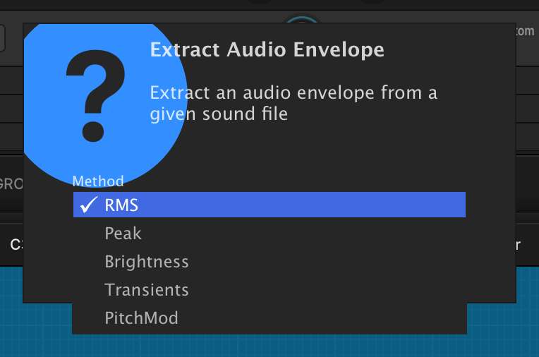
Drag-and-drop audio files onto the envelope to create envelope points, then choose an extraction method from the following:
-
RMS: extract the average level of the audio file.
-
PEAK: extract the peak level of the audio file.
-
BRIGHTNESS: extract the brightness envelope (i.e. spectral centroid / center of mass evolution over time) of the audio file.
-
TRANSIENTS: extract the transients of the audio file.
-
PITCH: extract the pitch of the audio file.
Multi LFO
Complex LFO with sine, triangle, square, saw, and random contributions.
The Multi LFO can be tempo-synced or set to discrete time values.
The FREQUENCY control sets the duration of one cycle of the LFO. When TEMPO SYNC is enabled, the cycle duration ranges from 32 bars down to 64th-note triplet, synced to Falcon’s tempo. When TEMPO SYNC is disabled, the cycle duration is in Hz (cycles per second) with super high speed up to 20 Hz.
To set the point within the LFO cycle where it will begin when triggered, change the PHASE (0–1) control. The image of the waveform will update to show the result of the phase change.
RISE TIME (0–10 s) is a time period during which the Depth ramps up to its full range.
SINE (±100 %), TRIANGLE (±100 %), SQUARE (±100 %), SAW (±100 %), and S&H (±100 %) sliders set the contribution of each waveform to the composite LFO output. All values are summed to form the final LFO shape. The square contribution has its own PULSE WIDTH (5–95 %) control.
DEPTH (0–100 %) controls the total vertical value (amplitude) range of the LFO’s cycle.
The default range of the LFO cycle is from −1 to +1 (bipolar). For a range of zero to +1 (unipolar), disable the BIPOLAR mode button.
INVERT flips the polarity of the composite waveform, turning its peaks into troughs. It acts before the unipolar conversion, so the shape is still mirrored when BIPOLAR is disabled, and the output stays within the zero to +1 range.
NORMALIZED rescales the composite waveform so its peak stays within the LFO’s output range, regardless of how many of the SINE/TRIANGLE/SQUARE/SAW/S&H contributions are summed.
SMOOTH (0–1 s) sets the amount of smoothing applied to transitions in the composite LFO waveform.
TRIGGER MODE determines how the LFO is triggered:
-
RETRIGGER: Each trigger of the LFO starts from the beginning of the LFO’s cycle.
-
LEGATO: Any simultaneous triggers of the LFO will not trigger the LFO again, and will start at the same place as any other concurrent triggers. All triggers will be released together when the last one is released.
-
NO RETRIGGER: The LFO runs continuously, triggering from the beginning when Falcon’s playback starts or stops.
-
SONG: The position will sync with the host position in bar/beat.
MANUAL TRIGGER (0–1) restarts the LFO cycle on demand, without a note, as soon as its value rises above the halfway point. The cycle starts again at the PHASE position, the Rise Time ramp restarts from zero, the smoothing is cleared and the S&H contribution draws new random values.
Parametric LFO
The Parametric LFO generates a cyclical modulation using parametric controls such as Shape, Symmetry, Pulse Width and Swing for a totally unique waveform that can evolve in real time.
The FREQ control sets the duration of one cycle of the LFO. When TEMPO SYNC is enabled, the cycle duration ranges from 32 bars down to 64th-note triplet, synced to Falcon’s tempo. When TEMPO SYNC is disabled, the cycle duration is in Hz (cycles per second) with super high speed up to 50 Hz.
To set the point within the LFO cycle where it will begin when triggered, change the PHASE (−1 to 1) control. The image of the waveform will update to show the result of the phase change.
DEPTH (0–100 %) controls the vertical value (amplitude) range of the LFO’s cycle.
SHAPE (±100 %) morphs from a flat line (−100 %) through triangle (0 %) and sine to square (+100 %); PULSE WIDTH (0–100 %), SYMMETRY (±100 %), and SWING (0–200 %) can be utilized to generate waves such as sawtooth ramp-up and down.
The default range of the LFO cycle is from −1 to +1 (bipolar). For a range of zero to +1 (unipolar), disable the BIPOLAR mode button.
TRIGGER MODE determines how the LFO is triggered:
-
RETRIGGER: Each trigger of the LFO starts from the beginning of the LFO’s cycle.
-
LEGATO: Any simultaneous triggers of the LFO will not trigger the LFO again, and will start at the same place as any other concurrent triggers. All triggers will be released together when the last one is released.
-
NO RETRIGGER: The LFO runs continuously, triggering from the beginning when Falcon’s playback starts or stops.
-
SONG: The position will sync with the host position in bar/beat.
Script Event Modulation
A modulation source driven by a Script Processor rather than by the keyboard or a shape: a script sends target values to it with sendScriptModulation, and the modulator ramps to each value it receives.
EVENT ID (0–127) is the identifier the modulator listens on, and must match the id the script sends.
The default range of the output is from −1 to +1 (bipolar). For a range of zero to +1 (unipolar), disable BIPOLAR mode.
Smooth Random
Random LFO generator with smooth evolution.
RATE (0–1000 Hz) sets the modulation speed. At 0 Hz the signal holds its current value.
DEPTH (0–100 %) controls the vertical value range of the modulation.
RANDOMSTART sets a random start position after each trigger.
BIPOLAR sets the modulation range as bipolar (−1 to +1) or unipolar (0 to +1).
TRIGGER MODE determines how the LFO is triggered:
-
RETRIGGER: Each trigger of the LFO starts from the beginning of the LFO’s cycle.
-
LEGATO: Any simultaneous triggers of the LFO will not trigger the LFO again, and will start at the same place as any other concurrent triggers. All triggers will be released together when the last one is released.
-
NO RETRIGGER: The LFO runs continuously, triggering from the beginning when Falcon’s playback starts or stops.
Step Envelope
The Step Envelope is a programmable pattern sequencer. The Step Envelope can be tempo-synced for steps of musical divisions, or set to discrete time values.
The value of each step can be set by clicking and dragging vertically. You can also click and drag horizontally to draw a shape over multiple steps. To clear all steps, right-click and choose RESET ALL VALUES. To view the step editor in finer detail, choose the edit button in the module header to open it in a large overlay view. Press anywhere outside the overlay to dismiss it.
The number of steps in the grid is set with the STEPS control, from 1 step up to 128 steps. The FREQ (0–20 Hz) control sets the rate at which the sequence advances from one step to the next. When TEMPO SYNC is enabled, step duration ranges from 32 bars down to 64th-note triplet, synced to Falcon’s tempo. When tempo sync is disabled, step durations are in Hz (steps per second).
The default range of each step is from zero to +1 (unipolar). For a range of −1 to +1, enable BIPOLAR mode, which is useful for LFO-like patterns.
DEPTH (0–100 %) scales the whole sequence, multiplying every step level by that amount, so the pattern keeps its shape while its overall amount of modulation is reduced; at zero the Step Envelope outputs nothing.
The Step Envelope’s INTERPOLATION MODE determines how each step’s value transitions to the next. With the default Hold mode, each value is held for the duration of the step, then immediately jumps to the next step’s value; with the alternate Spline mode, each value transitions to the next with a continuous spline curve.
The Step Envelope’s TRIGGER MODE determines how the envelope is triggered. It offers the Retrigger, Legato and No Retrigger modes described in LFO › Trigger mode.
MANUAL TRIGGER (0–1) restarts the sequence from its first step on demand, without a note, as soon as its value rises above the halfway point, so an automation curve or another modulator can restart the pattern. In No Retrigger mode the sequence normally follows the host timeline; the first manual trigger detaches it from that timeline, and from then on the sequence advances from its own restarted position.
SMOOTH (0–1 s) sets the amount of smoothing for each step.
Voice Modulator
A polyphonic step-sequencer that generates independent modulation signals per voice. Create animated pads, evolving sweeps, and rhythmic motion with sequences of up to 16 steps.
- When multiple notes are played at once, the number of triggered steps depends on the number and timing of the notes.
The value of each step can be set by clicking and dragging vertically. You can also click and drag horizontally to draw a shape over multiple steps. To clear all steps, right-click and choose RESET ALL VALUES.
The number of steps in the grid is set with NUMSTEPS (1–16).
LEGATO determines how the steps are triggered:
-
OFF: The sequence advances one step for each new note input. If multiple notes are played simultaneously, the sequence will advance by the number of notes played. The triggering position continues from the last triggered step.
-
ON: A note played while no other note is held restarts the sequence from the first step. Notes added on top of a held chord keep advancing it, as in OFF mode.
Modulation Sources
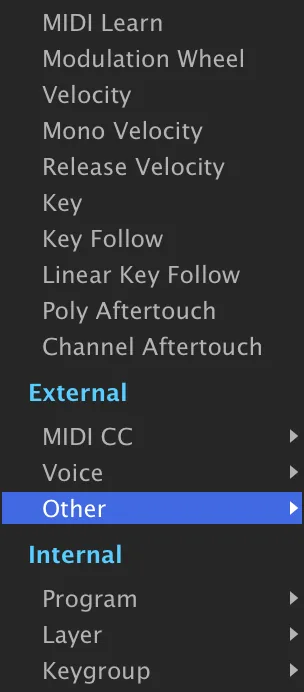
The menu opens on an unlabeled list of the most frequently used sources, followed by the External and Internal sections.
A quick overview of the available sources:
Quick
- MIDI Learn — opens the MIDI Learn dialog to quickly assign a control message from your MIDI controller.
- Modulation Wheel — uses the modwheel (or CC#1) of your controller.
- Velocity — uses MIDI note-on velocity.
- Mono Velocity — uses the last incoming MIDI note velocity.
- Release Velocity — uses MIDI note-off velocity.
- Key — uses MIDI notes as a unipolar value from left to right.
- Key Follow — uses MIDI notes as a bipolar value (C3 centered) with a curve.
- Linear Key Follow — uses MIDI notes as a bipolar value (C3 centered) with no curve.
- Poly Aftertouch — uses polyphonic aftertouch messages.
- Channel Aftertouch — uses channel (mono) aftertouch messages.
External Sources
The External section groups the external sources into submenus:
- Macros — the macros already added to the program; shown only when the program has macros.
- MIDI CC — manually assign a MIDI Control Change message from the menu.
- Voice — Velocity, Mono Velocity, Release Velocity, Key, Key Follow, and Linear Key Follow.
- Other — the remaining note-driven and controller sources:
- Alternate — alternates the value with each note.
- Organ Pan — uses organ-style panning.
- Unipolar Random — creates a randomized unipolar value for each note press.
- Random — creates a randomized bipolar value for each note press.
- Unison — uses unison messages.
- Unipolar Unison — uses unipolar unison messages.
- Pitch Bend — uses the pitch-bend message of your controller.
- Poly Aftertouch — uses polyphonic aftertouch messages.
- Channel Aftertouch — uses channel (mono) aftertouch messages.
Internal Sources
Internal sources route from any modulator already instanced elsewhere in the patch — the modulator types documented earlier in this chapter — organized into submenus that mirror the node at which each source lives: the effect rack holding the destination, Master, Part, Program, Layer, and Keygroup. Only nodes at or above the destination are offered. For a destination inside a program, Master and Part are also left out, so the program does not depend on where it is loaded.
Scripting in Lua
Scripting in Lua
Scripting in Falcon uses UVIScript, a domain-specific scripting language built on top of the Lua scripting language. Scripts in Falcon are essentially MIDI effects with advanced capabilities, with access to all of Falcon’s synthesis engine modules. Scripts can also define their own interface, so that you can interact with the script in real time.
UVIScripts are saved as text documents with a .lua extension, and loaded with Falcon’s Script Processor module. For general information on using the Script Processor module, see Interface › Events Tab and Event Processors › Script Processor.
Example
To help demonstrate UVIScript, here’s a simple example script for a pitch inverter (available in the Script Processor module as a factory preset, under UtilitiesInvert Pitch).
CenterPitch = Knob("Center Pitch", 60, 0, 127, true)

function onNote(e)
    local center = CenterPitch.value
    local delta = e.note - center
    local note = center - delta
    if note >= 0 and note <= 127 then
        playNote(note, e.velocity)
    end
end

function onRelease()
    --
end
Here’s what this script looks like in Falcon’s Script Processor.

This script creates one knob, which sets the script’s center pitch value (line 1). When a Note-on event occurs (line 3), the note’s pitch value is evaluated and modified relative to the center pitch value (lines 4–6), and then the note is played with its modified pitch value (lines 7–8). For example, if the center pitch is set to C3, when a C2 is triggered a C4 would be played instead.
The empty onRelease function swallows incoming note-off events instead of passing them on. The inverted note does not need them: a note started with playNote and no duration is released automatically when the key that triggered it is released.
Full Documentation
For more information on writing your own UVIScripts, please refer to the latest online documentation at: uvi.net/uviscript.
For more information on the underlying Lua scripting language, see lua.org/docs.html.
Factory Presets
Falcon Factory
Falcon ships with 1,600+ hand-crafted factory patches covering. classic synthesis, percussion, physical modeling, granular hybrids and. more. Presets are provided separately from the program — if you. haven’t installed them yet, grab them from your UVI Portal or the My. Products page of your UVI account.
01 — Ambient
63- Abyss
- Aerith
- After Midnight
- Ambidrone
- Arena
- Below The Surface
- Black Fields
- Bowed Cymbals RR
- Compass
- Confused
- Dark Nights
- Digital Drone
- Discolored
- Distant Memory
- Downfall
- Dune
- Dust Clouds
- Earth Stood Still
- Far Beyond
- Flute Dreamer
- Geist
- Ghostphone
- Granular Cave
- Haunted Town
- Lonely Guitar
- Long Ascent
- Lost Highway
- Midsummer
- Monster Horn Orcs
- Night Travel
- Orbit Drones Split
- Outside
- Paradise
- Piano Mantras Split
- Pieces of Star
- Purple Gaze
- Rigel
- Runes
- Sawdust
- Shimmering
- Softractive
- Sol
- Sonar Drops
- Spectral Flute Mystery
- Spheres
- Storm Synth
- Stratosphere Drone
- String Dome
- Sub Sine City
- Subject 939
- Submarine Escape
- Supernova
- Surreal Cicadas
- Tears
- The Depths
- The Faculty
- Urban Mantra Split
- Vocal Spheres
- Void Confort
- Vulcan Rumble
- Washed Out
- Water Resonances
- Whale Drum Drones Split
02 — Arpeggiated
120- 303 Motion
- Apogee
- Arp Hopwood A
- Arp Hopwood B
- ARP Voyage
- AxySystematic
- Baratro
- Bass Trance Motion
- Beats
- Blue Vibe
- Breather
- Cheap Synth Clouds
- Click Gear
- Concert Echo
- Convolve
- Cosm
- Dark Digital
- Dee Tiv
- Desert Highway
- Dirty Money
- Disto Box
- Divider Arp
- Dream Generator
- Eidolon MW
- Evening Pluck
- FM Dream
- Fractalized
- Fraction
- Fragile Arpeggio
- Freq Man
- Fresh Air
- Gate on Wheel
- Goa Motion
- Hiccup Wheel
- Holiday
- Hotaro
- Hybridation Wheel
- Hypnotic Arp
- Idiom
- Ja Tmospheric
- Key Bell Magic Motion
- Level Two
- Magic Run
- Marimbox Wheel
- Mayhem Cycle
- Melatonine
- Micro Arp
- Minor Redux
- Monoslide
- Motifs
- Multiverso
- Nightlife Red
- Numb
- Oniric
- Opossum
- Organic TM
- Ostinarp
- OT Bass Line
- Pad Peggio
- Padouble Arp
- Perc Lead Arp
- Petite Musique
- Phase Motion
- Popcorn One
- Proto Kalimba
- Psy Bass Motion
- Pulsation
- Radio Lines
- Random Motion A
- Random Motion B
- Real E.T
- Retro Moment
- Retro Nostalgia
- Round Chordinet
- Round Robinet
- Run Baby Run
- Runner
- Sand
- Santa
- Scavengers
- Sections
- Shaker Dance
- Simple Efficient
- Skylight Add
- Smooth Crime
- Smooth
- Snowflakes
- Sofitel Night
- Solar System
- Solarize
- Souz AcidB
- Space Christmas
- Spiral Arps
- Sport Arpeggio
- Stargazers
- Stellar Pax
- Stranger Synth
- Stray
- String Quencer
- Strum the Folk Up
- Strum the Funk Up
- Sunday
- Sweep Arp
- Tape Trash
- Textravaganza
- Time Stood Still
- Trance Arp
- Trance Pluck
- Tremolo Arp
- Tri Split Analog
- Typewriter
- Vintage Arp
- Violet Sky
- Wake up the Arp
- Weaver Mono
- Welcome Martin
- White Swarm
- Willow Pattern
- Xylo Dancing
- Yorubai
03 — Bass
215- 100in1
- 303 Possibilities
- 303 Stab Bass Dirt
- 808 Line
- 808 Mate
- Afford
- Angry Bot
- Angry Louis
- Angry Motion
- Archon
- Army Of Bass
- Arpenta
- AV-98
- BA Shomp
- Bad Dreamer
- Balarbas
- Basil
- Bass Add Reina
- Bass Analog A
- Bass Analog B
- Bass Starter
- Bass Story
- Beast
- Big Sleep
- Biggy
- Blizzard
- Blur
- Brick Vince
- Brutalis
- Cheap Tuned
- City Bass
- Clipping Aggression
- Coastal Halftones
- Couka Growla
- Crime
- Cyber Brahms
- Cymbal Bass
- Dancing Fifth Bass
- Dbstp Pattern A
- Dbstp Pattern B
- Dbstp Pattern C
- Dbstp Wanna Growl
- Dharma Bass
- Digital Bananas
- Digital Ghosts
- Dirty Wooble
- Dist Leadbass
- Disto Eight
- Disto Run
- DnB Reese A
- DnB Reese B
- DnB Run
- Doggy Dog
- Down Bass Motion
- Drive Presence
- E-Bass
- Fat Phaser Bass
- Fedde Le Grandiose
- Fireworks Bass
- Flux
- FM Hammer
- FM Morph Wheel
- FM Vee Bass A
- FM Vee Bass B
- Foxy Bassy
- Freaky Freaky
- Funky Bron
- Funky Magination
- Future Shock
- Gamma Bass
- Gauss Bass
- Genesis
- Goto Kick
- Grinder
- Growl Alarma
- Growl Pro Talk
- Growlin
- Growling
- Hard Wheel
- Harsh Bass
- Hawkins Lab
- Heldens
- Hex Bass
- Hi Five
- Hiccup
- Hollow Price
- Hot Bananas
- House Brute
- I Am The Law
- Impact Disc
- Intensity
- Justice Bass
- Kalach Mikos
- Line
- LoFi Cinematic
- London Funk
- Low Five
- Machina
- Magnetic 1
- Magnetic 2
- Metal Skin 1
- Metal Skin 2
- Metropolis
- Mister
- Model Bass
- Modular Phase
- Monster Growl
- Morphine
- Nasty BasSci
- Nasty Line
- Night And The Bass
- Noisy Org
- Noisy Suba
- Oak
- Oblivion
- Oh Eight
- Orgones
- Out Run
- Overdrive
- Oy
- Paris Hilpluck
- Party Enclume
- Piano Hammer
- Pluck Acidified
- Pluck Thunder
- Plucked 7th
- Polymer
- Praxis
- Psy Bass Trance
- Pulse 1
- Pulse 2
- Pulse Bass
- Pure Sub
- PWM Closing
- PWM Sweep
- Rando Bass
- Rational
- Reso 1
- Reso 2
- Retro Line
- Retro SciFi
- Ride On
- Rocket Man
- Rude
- Running
- Saw Glide
- Saw TB Clean
- SciFi Classics
- Screamtable
- Sea Cyber Dog
- Sedatives
- Selmer
- Seq Triplets
- Seventh Rise
- Sexy Growl
- SH101 Basic Saw
- Shatter Bass
- Shine
- Shorty Wheel Bass
- Show Me Robin
- Sine FoldBack Wheel
- Skid Tomcapt
- SoBadBass Wheel
- Softcastel
- Square Percussion
- Square Pump
- Stab Bass
- Stealth Bass
- Studio 54
- Sub Finger Chorus
- Sub Sine Driwheel
- Sub-Grime Bass
- Subline
- Suction Bass
- Sumerian
- SuprAnalog
- Swordfish II
- Sync Force
- Sync PWheelM
- Tape Bassline
- TB Drive Wheel
- Techno Caravan
- Texturalis
- The Hell
- Tokyo Funk
- Torn
- Train Spotting
- Transformer
- Typical 80s A
- Typical 80s B
- Undercover Bass
- Very LoWuis
- Wandering Bass
- Warming
- Wave FM
- Wheel Angry Growl
- WO Damian Harley
- WO Dub Shake
- WO Jerk
- WO NRV
- WO Razor
- WO Rolling
- WO Scratch Growl
- WO Slide
- WO Somersault
- WO Zombie Glide
- WO Zombie
- Wolves
- World Up
- Wyrd
- Xbass Wheel
- XBeat Bass A
- XBeat Bass B
- Xicyber
- Yo Fav Bass
04 — Bells
54- 1985
- Bella Dictive
- Bike Bells
- Box of Bells
- Bright Slider
- Can Keys
- Castle
- Cathedral
- Chime Glide
- Clots
- Composite Glass
- Cristal Clear
- Dark Bell
- Dark Wind Bell
- Delicate Keys
- Digi Bells
- Eight Grains
- El Bastos
- Ethereal Bells
- Everlight
- Expressive
- Falcontasia
- Fog Chime
- Glowing
- Humiditey
- Kalimbellish
- Lowdrive FM
- Manga BellZ
- Memories
- Mix Bellissima
- Mystic Bowls
- Old Bell
- Organic Bottom
- Organpad Bells
- Pink Bottle
- Play With Me
- Relax
- SoToy
- Sweep Phase Bells
- Syn Bell Motion
- Synthetic Bells
- Thai Bells
- That Moment
- Thorus Bell
- Tubular FM
- Vick Celeste
- Wavetable Bell 1
- Wavetable Bell 2
- Wha Wheel Bell
- Whistle Pad
- Wide Keys
- Winter Keys
- Xmas Analog 1
- Xmas Analog 2
05 — Brass
37- A Boffins Prescription
- Alternate
- Bouncing Brass
- Brass Colors
- Brasstringue
- Brassy Arpeggios
- Brassy Saw
- Burgandy Bass
- Caelus Texture Synth
- Chordalis 1
- Chordalis 2
- Dark Chamber
- Detuned Saw Brass
- FM Old School Brass
- Full Analog Brass
- Funky Poly Brass
- Gotham Brass
- Jazzy Ambient
- Last Minute Brass
- Lowhorns
- Lush Saw
- Majestic Saw
- Majestic Soft
- Mamy G Brass
- OB Expression
- Odd Brass
- Plastic Trumpet
- Safe Bicycle
- Saw Motion
- Saxofon
- Scanner Synth
- Soft Synth Brass
- Stab for Chords
- Steady Analog Brass
- SY Brass Rhythm
- Wave Brassy Bell
- Yes Bari
06 — Chords
41- 8bit Catharsis
- A Street Light
- Ambi Strum
- Bass Minor
- Beauty Bed
- Best Hopes
- Cheezily
- Chord Saw Min7911
- Chord Sine FM Min7
- Chord Sine Min7911
- Chord Tek
- Chord to Jump
- Chorder SEQ
- Dreams Made
- Dust Chord
- Gliss Phaser
- Glitz Bells
- Hong Kong Pad
- Jolene
- Love Chord
- Major Chips
- Neon Chord
- Night Garden
- Poison
- Retro Wave Chord
- Roxy Moxy
- Scout Bass
- Session Stones
- Simplicity
- Sing To Sleep
- Sloppy Saw
- Snow
- Stab Chords BP
- Stab Chords LP
- Stop Rocking
- Syn Accordeon 80s
- Tropicalouis
- Vangelis Chords Cm
- Violet Drive
- Vowheel Morph
- Winter
07 — Experimental
59- A Long Way
- Almost Music
- Ambient Pad Quencer
- Aquatic Apes
- Attack Synth
- Auto Caroussel A
- Auto Caroussel B
- Bowed Crotales Cloud
- Calmy T Jane
- Chimes Story
- Complex Lander
- Contremy Bass
- Cosmic Grain Pad
- Cosmic Phases
- Dark Pad Wheel
- Descender
- Diminished Scanner
- Drunken Master
- Eighchoes
- Electrons
- Endomorphine
- EP ON LOoPp
- Fibonacci Synth
- Flower Synth
- Glass Drones Split
- Gramuller Xperience
- Granular Arp Scape
- Granular Bells
- Granular Lounge
- Gravitational 1.6
- Gulp Cello
- Hybrid Piano Harmonics
- Interferencing
- Interstellar Emy
- Labratory
- Misty Morning
- Noise Quencer
- Orion Core
- PicthApAd
- Prehistoric
- SE Machines Wheel
- Secret Facility
- SnH Layering
- Space Violin
- SPLIT SFX Darkness
- SPLIT SFX Drummers
- Subban
- Superglider
- Surreal Singer Split
- Swordfish World
- The Glacier
- Thingamajig
- Tin Can Program
- Tinkle Textures
- Tyranic Symphony
- Urban Step Wheel
- Valse
- Vaporave
- Vocal Wall
08 — Expressive E
51- Adrialik
- Africa
- Amidio
- Angrybass
- Bellissima
- Bladum
- Bloom
- Blute
- Brown
- Burton
- Calculator
- Clavisquare
- Deadpool
- Dreaded
- Duplo
- Erlin
- Ether
- Fulldisclosure
- Gloomy
- Grabuj
- Green Parrot
- Hauntingbit
- Helium - Arpbonus
- Helium - Bassbonus
- Helium - Keybonus
- Helium - Leadbonus
- Helium - Padbonus
- Horns
- Ishtar
- Jaz
- Jungleboogie
- Kermit
- Kokiri
- Madarp
- MakeSomeNoise
- Marthe
- Mercury - Arpbonus
- Mercury - Bassbonus
- Mercury - Leadbonus
- Mercury - Pluckbonus
- Mercury - Stabbonus
- Musicismath
- Nightcall
- Padira
- Roybgiv
- SqrFilter
- Steel
- Tiesta
- Tycho
- Vanity
- Woody
09 — Fretted
15- Broken Guitars
- Color Guitar A
- Color Guitar B
- Cyber Guitar
- Dream Guitar
- EGuitarella
- Electric Pick
- Guitars Parts
- Nylon Guitar Model
- Nylon Harmonics
- Old Guitar Pluck
- Orguitar Dream
- Rehammer
- Santoorino
- Yokohama
10 — FX
74- Arpeggio Rain
- Bells 2019
- Bouncing Pluck
- Bow Braam
- Bowed Cymbal Mystery
- Chainsaw A
- Chainsaw B
- Cheers
- Chopper
- Circle UFO
- Computer Wheel
- Crickets
- Dbstp Riser Long
- Downer Beast
- Drum Electric Tom
- Drum Noise Hit
- Eucl. Square Drops
- FM Dancer
- FM Pointillism
- FM Random Wheel
- FM Tronics
- FM UFO
- FMayhem
- Freeze Coin
- FX Furtive
- FX Orbital Junk
- FX Unsync Riser
- Game Over
- Garbled Well
- Ghost Flutes
- Heartbeat
- Hit Elevator Down
- Insect Swarm
- Landing FM Patch
- Liquid Scapes
- Los Bomberos
- Mario Die Wheel
- Mario Jump
- Mario Pipe Wheel
- Mayhem Muller
- Medispace
- Noisotron
- Noisy Filth A
- Noisy Filth B
- Non Sensor
- Outer Space Radio
- Phase One
- PolyQuencer
- Predator Scan
- Puke Man
- Radio Traffic
- Rain Heavy
- Retro Gaming
- Rise 02B
- Saturn Rings
- Saw Ramp Down
- Saw Ramp Up
- Sewer FX
- Sine Ramp Down
- Space Boomerang
- Space InvaWheels
- Spastic Game
- Star Traveler
- Surfer Gutural Brain
- Synced Mini-Licks
- Talking Droids
- The End
- The Hammerites
- Theater X Intro
- Time Machine
- Venus Crier
- Vinyl Noise
- Wind Freezing
- Zebuwheelon
11 — Keys
97- Ballad Plucker
- Ballad
- Belladonna
- Board Toronto
- Brightpop Keys
- Busy Bee
- Cascadia
- Cassette Sines MW
- Celestial
- Chillbeats
- Chorde Piano
- Christmas Tape
- Clavi Station
- Clockworks
- Cloud Keys
- Crystal Piano
- Days Of Old
- Delta
- Dirty Toy Piano
- Doom Metal
- Doom Octaver
- Doorways
- DX Mania
- Eighty Nine
- Ekora
- End of Summer
- Evanescense
- Fader Ash
- Feather Swells
- FM Dark Keys
- FM Electric Grand
- FM Groover
- FM Sitar
- FM Softly
- FM Tremolo
- Gaze
- Ghost Pianissima
- Glassphone
- Glassy Key
- Glide Mod
- Gradient Byzantine
- Hollow Piano
- Hybrid Piano
- Hyperdiffused
- Just A Warm Sine Wave
- Key Battered
- Key Frost Piano
- Key Therapy
- Keys 90 Pads
- Keys Airfall
- Keys Vocalight
- Kley
- Luminous
- Meadows EPiano
- Meadows
- Miyaky
- Moonbeam Keys
- Morning Keys
- Mutant Nylon
- N-Circuit
- Old Skull
- Old Town
- Parallax
- Paul Wurlitzer
- Placid Keys
- PolySaw
- Power Keys SnH
- Pure FM Tines
- Quanta
- Sky Cities
- Slide Bright
- Small Keys
- Smooth E-piano
- Snowfall
- Soft Glide
- Somnia
- Step FM Keys
- Strum Vater
- Strum Zilo
- Super Soft EP
- Superstar
- Sweet Phase
- Sync Ambient Keys A
- Sync Ambient Keys B
- Synth Antic
- Tajine Night
- TapeIt
- Textural Keys
- Thorus Softkeys
- Thumb War
- TimpEthnic
- Tiny Harp
- Toikeys
- Toy Klimb
- Vaporsine
- WahKey
- WaterKeys
12 — Lead
111- Aged Grit
- Ali3n
- Arcade A
- Arcade B Wheel
- Around Lead
- Avicclead
- Awesome Perc Lead
- Bite Lead
- Blue Lead
- Blur High
- Blur Low
- Chamalead
- Chiffer Flute
- Chinese Violin
- Cinton in Da Space
- Cold Water
- Companion
- Crossfade Hardlead
- DaMt Punk
- Derailer
- Digitalead
- Dirty Vl Lead Bass
- DistortedSK
- Double Strike
- Dream Funk
- Fa Dunk
- Flat Heat
- FMish MonoPoly
- Forest Green
- Franken Lead
- Funka Nada
- Funky Frog
- Funky Res
- Funky Synth
- Future High
- Germanic Lead
- Glider Pluck
- Gonzalead
- Hardsync Spice
- Haric Hoover
- Ice Planet
- Innocent Leader
- Jaw Lead Sequence
- Jimmy Digi
- Keytar Hero
- Lead Acid Distortion
- Lead Angry Saw
- Lead Brass Soft
- Lead Clean SuperSaw
- Lead Clean SuperSquare
- Lead Noisy Fat
- Legato
- Lumen
- Lux Lead
- Mad Mono Stack
- Mayfield Flute
- Mercury Lead
- Metalizer
- Mini Ribbon
- Mono Synco
- Moore Loud
- Mouth Lead
- Muddy Lead
- Nasty Shaper
- Neige
- Noisy Detuned
- Nostalgia
- Obese Lead
- Octaves Glider
- Outer Invasion
- Panflute
- Philicorlead
- Play Me Low
- Power Lead
- Psychotic Tac
- Reduce Solo
- Retro Lead
- Sample Hold Lead
- Saw Classic
- Saxy Wave Solo
- Screaming Lead
- Shaba Duo
- Sine Equanone
- Singing
- Single Saw Brass
- Sino Lead
- Soft Lament
- Soft Mood
- Soviet Vintage
- Sparks
- Speculos
- Split PWM
- Sunny Lead
- Swell Harp Funk
- Synker Kraut
- Synth Lead Prodigy A
- Synth Lead Prodigy B
- Synth Lead Prodigy C
- Tachyon
- Tape Saw
- Theremin Mania
- Traced Circuit
- Trap Oriental
- Ultra Noisy Lead
- Ultra Skinny
- Winderland
- X-Breather
- Xtreme Saw
- Ze Brocante
- Zodiac MW
- Zoologic
13 — MPE
34- Analog Cello
- Basic Sine PD
- Basic Wavetable Index
- Basic Wavetable Step
- Chameleon Synth
- Chiffer Flute
- Clean SuperSaw
- Clean SuperSquare
- Contremy Bass
- Daft
- Dafta Wheela
- Double 5th Pad
- Eye Lead
- Fibonacci Synth
- Funk Synth A
- Funk Synth B
- Ghost Bell
- Haric Hoover
- Majestic Soft
- Marimbox
- Meditation Pluck
- Noisy Detuned
- Pluckzicato
- PW Pad
- Soft Killing me
- Softcastel
- Solo Flight
- Space Violin
- Step It Up
- StepOminous Pad
- Sweep Pad
- Table Arp
- Time Bubbles
- Wave Guide
14 — Organ
28- Blues Jazz
- Caroussel
- Crazy Organ
- Cyber Pipes
- Dirty B3
- Doors 2015
- Dracula Night
- Drawbar Soft
- Explosion of Blues
- Full Distospeed
- Gold Times A
- Gold Times B
- Gold Times C
- Gold Times D
- Las Vegas Church
- Morgan Free
- NoisOrg
- Organ Jumper
- Organalog Perc
- Organwheel Pad
- Oto Disco
- Overtone Synth
- Santanorgan Soft
- Self Playing Organ
- Simple One
- Sixty One
- Soft Modeled One
- Tars Organ
15 — Pad
162- 16th Chill
- A Free World
- Aeternal
- Animated
- Animator
- Aqua Move
- Arctic Pad
- Arrival
- Autumnal Questioning
- Beauty is Simple
- Bells Pad
- Blade 2000
- Bowed Cymbal Pluck
- Bryan Fairies
- Burning Rain
- Calm FM Fifth
- Calm Morpher
- Calm Shores
- Cinema
- Cinerain
- City Pad
- Days Gone
- Digimotion
- Discovery
- Dream Synth
- Dusty Night
- DX FM Pad
- Elixir
- Ether Cellos
- Ethereal Walls
- Evolver
- Experiwheel
- Feed Me Pad
- Flourished
- Forgery
- Geometry Drone Wheel
- Ghetto Cloud
- Glass Ring
- Glass Slow
- Glass World
- Glide Sine Lead
- Godrays
- Granular E-Bow
- Green Earth
- Harp Stretch Resonance
- Holographic
- Impulse Strings
- Interferoid
- Island Cello
- Isshak s Breath
- JMJ Satellite
- Land of Nowhere
- Last Minutes
- Living Harmonics
- Lonely Pad
- Lost in Pad
- Lost Tape
- Lunar Mission
- Lush Chords
- Maelstrom
- Meteor 1
- Meteor 2
- Midnight Organ
- Mimesis
- Moki
- Morning Pad
- Moving Parts
- Multi Saw Pad PK
- Nasal Pad
- Nashville Loops
- Night Feed
- No Justice No Peace
- Novachord Noir
- Octawheel
- Odd Even Synth
- Olympus Mons
- Orchestral Grains
- Organic Pad
- Pad Ethereal
- Pad Generic
- Pad Motion
- Pad Visor
- Padditive
- Pan Mod Pad
- Parabol
- Parsec
- Phasor Pad Gold A
- Phasor Pad Gold B
- Philadelphia
- PizzNL
- Planetary Cycle
- Play G Minor
- Pluck and Pad
- Pluck Box Wheel
- Pluck Delays
- Pluckzicato
- PPG Dream
- Primus Pad
- Prism
- Probabilism
- Pulsate Pad 1
- Pulsate Pad 2
- Pulsating Pad
- Purity Scanner
- Raffle
- Rainbow Wheel
- Realistrings
- Regular
- Reminisence
- Renewal
- Reversity
- Rich Pad
- Robotized Pad
- Salling Phase
- Score Twheelve
- Secret Translation
- Shiny
- Sine Dark
- Sines FM and Feedback
- Singing Glass
- Slow Motion A
- Slow Motion B
- Slow Space
- Slowdrive
- Soft Killing me
- Soft Light
- Soften
- Sognition
- Solar Winds
- Spinning Leaves
- Stalag Wheel
- Stallar
- Star Shine
- Static Pad
- Stellaria
- StepOminous Pad
- String Analog
- Strum Chaos
- Strumming Breeze
- Subtle Animated
- Sunrise Pad
- Sunrise
- Sunshine Stream
- Temptation
- The Return
- Thorus Pad 1
- Thorus Pad 2
- Tomb Raider
- Tutty Flutty
- TV Space
- Upside Down
- Vanilla
- Vantage
- Vintage Planar
- Vintage PWM
- Vinyl Whistle
- Wheel Multipluck Pad
- Wide Drive
- Wrong Dance
- WT Harmonics
- Xtreme Wet Pad
- Yannification
16 — Pluck
88- Analogica
- Asian Plucker
- Balaphin
- Barrel
- Beauty Island
- Bell Center
- Bright Club
- Cerulean
- Chip TV
- Comb String
- Cooder
- Drum Pluck
- Empyrean
- Endless Takassim
- Eventide
- Falling Grains
- Fast Harp Bell
- Film Pluck
- Fizzy Drink
- Fractured Vibes
- Frostbite
- Gamelan Plucker
- Garbage
- Happy Steel
- Harpluck
- Hit Pluck
- Hosono
- Impulse Pluck
- Kalimba Clouds
- Key Bell Darbuka
- Kyoto Strum
- Lazer Harper
- Lefty
- Malletophone
- Marimbox
- Mecha
- Meditation Pluck
- Melodeek
- Metallic Flute Pluck
- Metsine
- MicroAb
- Mine de Rien
- Minnow Perc
- Morbid
- Multisampluck A
- Multisampluck B
- Multisampluck C
- Multisampluck D
- Multisampluck E
- Mutan Mute
- NeoSoul Red
- Noisy Poly
- Noisytron Flute
- Organism
- Oriental Plucker
- Over Dreaming
- Pad Mullerizer
- Perc Pluck
- Permuda
- Plasmon
- Pluck Mix
- Reverse Mallet
- Ricochets
- Rituals
- SciFi Harp
- Sensitive Voice
- Short Plucksyn
- Snow Land
- Snowflakes
- Soft Intro
- Space Pop Corn
- SteeLemmons
- Stick Corn
- Strum Gebob
- Tempitar
- Tinker Town
- Tower
- Tropical Pluck
- Tube Add
- UBahn
- Vibra Plucker
- Voltaic
- Water Pluck
- Wonder Pluck
- Wood Plucker
- Wooden Blocks
- Yamaho
- Zonophone
17 — Polysynth
86- Air Her
- Analog Chinese Split
- Analog Super Saws
- Assault
- Attack Pad A
- Attack Pad B
- Beatitude Interval
- Big Washer
- Bubble Gnome
- Chirping Lead
- Clean SuperSaw
- Clean SuperSquare
- CrossMod
- Cymatic Polyscape
- Dafta Wheela
- Dbstp Long Pattern A
- Dbstp Long Pattern B
- Dbstp Long Pattern C
- Dbstp Long Pattern D
- Dbstp Long Pattern E
- Dbstp Mosntry Growls
- Dee Add
- Dirty Moving
- Disto Box
- Down Side
- Drama Queen
- Dual Poly Filter
- Dub Short Stab A
- Dub Short Stab B
- Duosphere
- Explorer
- Fresh Funky
- Full Vintage
- Funky Step Wheel
- Fuzzy Reef
- Grunge Tabler
- Guitar Distortion Booth
- House Classic Gate
- Jim Star Boner
- Louis Funky Dub
- Major Oldfield
- ME Drumin Vowels
- Minor Oldfield
- Motion Prodigy
- Mullerade
- Noisy Wob
- One Bass Army
- Oyster Harp
- PoLFO Lee
- Poly 8Fifty
- Poly Blue Rim
- Poly Noisy Fat
- Polygon
- Polystic
- Pop Sync
- Pure Saw
- Pure Square
- Pure Triangle
- Right Nowwheel
- Saw and Pepper
- SAWarmer
- Short Growl Stab
- SID Waves
- Slow Burn
- Solo Flight
- Soundtrack Split
- Split Fire
- Spy Noso
- Stabby FM
- Stinger Synth
- Syn Prod Motion A
- Syn Stab
- Syncpad Lead
- Tangerine Split
- Thorus Cindy Pluck
- Thrillorus
- Trance Step
- Vanilla
- Velocity Pluck
- Washed Out
- Wavers MW
- Wavetable FM Evo A
- Wavetable FM Evo B
- Wheelcome Sample
- Wheeltable Pluck
- Witchcraft
18 — Pulses
24- Crazy Louis
- Crush Pad
- Dark River
- FM Walled City
- Goa Pulses
- Hovering
- Long Journey
- Megagate Power
- Minions
- Minor Arp Mayhem
- Minor Table Quencer
- Mouse Pluck
- Neon Memories
- Oliwheel Madness
- Prisunic
- Pulse Day One
- Pulse Day Two
- Pumping Split
- Runaway
- Saw Bandpass
- SH Play
- Skizze
- Table Quencer
- Vintage Motion
19 — Rhythmic
48- 8Bit Drum Loop
- Anticipate
- Attack Analog Drums
- Axe Loop
- BD Simple
- BS Groover
- Cerebraloop A
- Cerebraloop B
- Computer Synth
- Dbstp Noisy Pattern A
- Dbstp Noisy Pattern B
- DR 8Bit Dnb 174BPM
- DR Big Room 128BPM
- DR Dance 128BPM
- DR Dubstep 140BPM
- DR Triplet Trap 130BPM
- DR Zouk 110BPM
- Drive Thru
- Drum Sequencer Kit Basic
- Drum Sequencer Kit Multi
- Euclidian Rule C3
- Finger On
- Full Fuzz
- Future House 1
- Future House 2
- Future House 3
- Gaming Memories
- Hoohah
- Hotliner
- Jungle Road
- Moombah
- Net Sphere Engineer
- Night Percs
- Nightfall
- Old Circuit C3
- P-5000
- Poly Trig Arp
- Popcorn Train
- Prehistory 1
- Prehistory 2
- Prehistory 3
- Randomatron
- Retro Finger
- Rythm Poly Cycle
- Snare
- Tri Tek
- Tribal Generation
- Very Sketchy
20 — Sequences
154- 8Bit Soundtrack
- 8Fifty
- Adventure
- Agitated
- Analog Drops
- Analogica
- Approach Vector
- Automata Chimes
- Banana Split
- Before the drop
- Bis2fly
- Bliss Seq 1K
- Boids Nebulae
- Bouncing
- Brothers
- Butterfly Chords
- Chain
- Ching Sequence
- ChordArp
- Chorus Me
- Cityscapes
- Cleansing
- Clicky
- Closer
- Colors
- Crepuscular 1K
- Dancing Sines
- Dark Knight
- Decisions
- Deep Bass
- Descent
- Documentary
- Dynamic Synstring
- Eden
- Electric Church
- Ember Sequence
- Endless Droids
- ET did Tic
- Euclidean Eight
- Euclides Meets Bernoulli
- Exploration
- Far
- Fast
- Fezz Omy E
- Follow Me
- Forgotten
- Foundry
- Gameboy Bass
- Gameboys
- Gate Poly Mod
- Glass 1K
- Glockenny
- Happen 20 1K
- Harper
- Haunted Plates 1K
- Hologram
- HolowGramm
- Hon Jopkins 1K
- Hours
- House Clock
- House Mania
- Kensei
- Lalalalala
- Levels
- Light Exploration
- Light Motion
- Lurk
- Mambo Break
- Many Things
- Matrix Break
- Megatron
- Minor 7th Run
- Mist
- Motor
- MS Dot 1K
- Multi Bassline
- Multi Env Sync
- Multi Fannix
- Mysteriousity
- Naraka
- Neptune
- New Game
- Night Move
- Noise
- Norma 1
- Norma 2
- North Sequence
- Octavoto Pluck
- Ominous 1K
- Ominous Bassline 1K
- Pagoda
- Poly Layer
- Poly Precious
- Protected
- Pure Sine Concert
- Racer Spe
- Random Scanner
- Ravers Night
- Reflection
- Reneal 1K
- Retro SciFi II
- Ringmod Circuits
- Rubbery Glitch
- Rush
- Scene Change
- Sea Motion
- Seq Addiction A
- Seq Addiction B
- Seq Addiction C
- Serenity 1
- Serenity 2
- Shatterhand
- Sinephony
- Slow Bass
- Slow Movements
- Snowflakes
- Soaring
- Soft Marimbas
- Somnium
- Space Tour
- Sparks Around
- Static and Noise 1K
- Step It
- Strange Line 1K
- String It
- String Reflection
- Structure Drone
- Strumming in the Rain
- Subway Pulses
- Synapse
- Taper Sawyer
- Territory
- Textronic
- The Forest Ensemble
- Thug Bass Wheel
- Time
- Transformations
- Tri Layering
- Tribal Road 1K
- Triple Triangle
- Tunnel Sequence
- Turbolence
- Two Hands Split
- Ultra Ring 1K
- Under Pizzi
- Underscore
- Velocity Quencer
- Voltage Reso
- Wake up the Sun
- Warpy
- Waterfalling Mallets
- Wave AnaSeq
- Worlds 1K
- Xenon
21 — Strings
29- Alchemical Strings
- Ana Pizz
- Analogica
- Constellation
- Distant Memories
- Dreamy Strings
- Flyby Cello
- FM String
- Hybrid Sautill
- Low and High
- Maelstrom
- Melloz
- Noise Wonders
- Old Times
- Orchestrata
- Permafrost
- Physical Cello
- Retro
- Serendipity Pick
- Shivers
- Silver String
- Square Ensemble
- Staccastrings
- Stretch Bow
- String Fast Pluck
- Strings Bidule
- Symphonica
- Uneasy String
- Warm Strings
22 — Sweep
13- Big Table Synth Wheel
- Diverise A
- Diverise B
- Riser 1bar
- Riser 2bar
- Riser Growl
- Sample and Whold
- Saw Detune 8bar Up Down
- Short Analog Sweep
- Soft Saw 5th
- Sweep Trance Gate
- Transition Growl
- Ultra Soft 5th Res
23 — Voice
34- Almost Natural Oohs
- Arabic Aah
- Choir Boys
- Choir Hopwood
- Cinematic Vox
- Circle Formant
- Counter Formants
- Cyber Choirs 1
- Cyber Choirs 2
- Dark Choir Males
- FAirLightCON
- Formant Analog Choir
- Gate Ooh Atmos
- Guardian Angel
- Les Formants
- Little Monster Wheel
- Mahavish
- Melchior
- Ooh Choir
- Pheromones
- SC Vocal
- Subalterne
- Swirl
- Syncotron
- Talking Keys
- The Voice Inside
- Uni Vox Wheel Morph
- Vibrez
- VO Gate
- Vocal Growl Bass
- Vocal Meditation Drone
- Vocal Trap PK
- VocaLead
- Vox A Loid
24 — Winds
14- Alto Flutish
- Analog Lament
- Dark Majestic
- Delicate
- Disto Analog
- Flutey Noise
- Imaginary Blower
- Panoptic
- Pipes
- Places
- Retrowind
- Simple Analog Flute
- Synthax
- Wind Playground