Falcon includes over 90 high-quality effects, plus the legacy effects kept for older programs, categorized for easy navigation: Delays, Reverbs, Modulation, Filters, Equalizers, Amp and Stereo, Drive and Distortion, Dynamics, Pitch, Analysis and more. With effects suited for nearly every need from creative mangling to precise sound sculpting, mixing and analysis, Falcon provides a tremendous sound design facility.
Audio signal processors, available at every level from a keygroup up to the master.
- Analog Chorus
- Analog Flanger
- Analog BBD Chorus
- Ensemble 505
- Flanger
- Freq Shifter
- Granulizer
- Phasor
- Rotary
- Thorus
- Analog Filter
- Biquad Filter
- Brickwall Filter
- Comb Filter
- Crossover Filter
- Digital Filter
- Formant Crusher
- LPG
- Ladder
- Lowpass 12
- Lowpass 24
- One Pole
- Phasor Filter
- Rez Filter
- SVF
- Sallen-Key Filter
- Steiner Filter
- UVI Filter
- VCF-20
- VCF-20 Dual
- VCF-4023
- Vowel Filter
- Vowels
- Wahwah
- Xpander Filter
- Analog Crunch
- Diode Clipper
- Drive
- Exciter
- Fuzz
- Guitar Boxes
- Magnetic Bass Shaper
- Overdrive
- TS Overdrive
- Tube Amp
- Wavefolder
- Wave Shaper
- 3-Band Compressor
- 3 Band Limiter
- Compressor Expander
- FET Compressor
- Feedback Compressor
- Feedforward Compressor
- Gate
- Maximizer
- Opal
- Studio Limiter

Effect Rack
Modules in this category Read more ↓Delays
Analog Tape Delay

Analog Tape Delay is inspired by classic analog delays using reel-to-reel tape loops.
DELAY (40–2000 ms) sets the length of delay, in ms or bars/beats (if tempo-synced).
FEEDBACK (0–100 %) chooses the percentage of signal fed back into the module.
SPREAD (0–200 %) sets the stereo width of the delayed signal: at 0 % the echoes collapse to mono, 100 % (the default) leaves their stereo image untouched, and settings up to 200 % exaggerate it by boosting the difference between the two channels. Mono material is unaffected at any setting.
Distortion
DISTORTION MODE sets the style of distortion (Tape, Tape/Tube, and Analog), and TRASH (0–100 %) sets the amount of distortion.
Mix
DRY (0–100 %) and WET (0–100 %) knobs set the balance between the dry (unaffected) and wet (affected) signal sent to the module’s output.
Analog BBD Delay
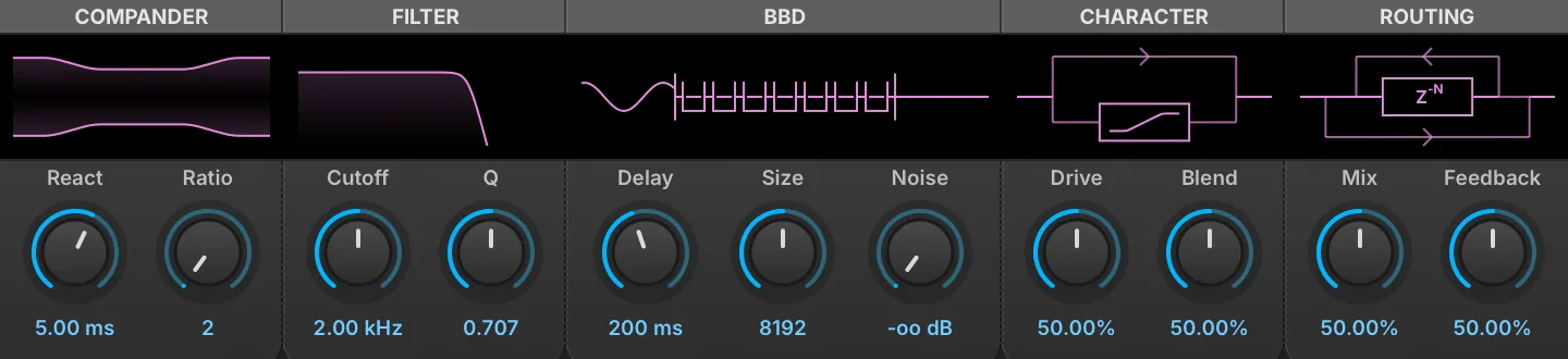
Analog BBD Delay models a bucket-brigade delay line, the chip that made analog delay pedals and rack units possible: the signal is passed from one capacitor to the next on a clock, losing a little bandwidth and gaining a little noise at every step. Delays from 10 ms to 10 seconds are available, and a compander brackets the chain as the originals did, to keep the noise floor down.
The five sections each carry a display above their knobs, and each display can be dragged: horizontally for the left knob of the section and vertically for the right, with Ctrl for finer steps.
Compander
REACT (1–50 ms) sets how quickly the compander follows the level of the signal, and RATIO (2–6) sets how hard it compresses on the way in and expands on the way out. The display draws the resulting range: Ratio closes the middle of the figure in, React steepens its ramps.
Filter
CUTOFF (20 Hz–20 kHz) sets the corner of the reconstruction filter and Q (0.500–1.000) its resonance. The filter sits inside the feedback loop, so it also damps the repeats: each pass through the loop crosses it twice, which is how the display plots it.
BBD
DELAY (10 ms–10 s) sets the delay time, in milliseconds or in bars and beats when the module is tempo-synced. SIZE sets the number of bucket stages — 1024, 2048, 4096, 8192, 16384, 32768 or 65536 — and with Delay decides the clock rate the brigade runs at: a short delay through a long chain clocks fast and stays clean, a long delay through a short one clocks slowly and darkens. NOISE sets the level of the chip’s own noise, injected ahead of the buckets. The display is a schematic of the brigade itself, one bucket per Size step, passing charge along on each tick of the clock.
Character
DRIVE (0–100 %) sets how hard the input hits the soft clipper, and BLEND (0–100 %) crossfades between the clipped path and the clean one. Saturation is applied to everything entering the delay line, the feedback included, so repeats compound it; the dry signal in the final mix is left untouched. The display shows the two paths, with the clipper’s own transfer curve drawn inside the box.
Routing
MIX (0–100 %) sets the balance between the dry and delayed signal, and FEEDBACK (0–100 %) how much of the output is returned to the input.
Diffuse Delay
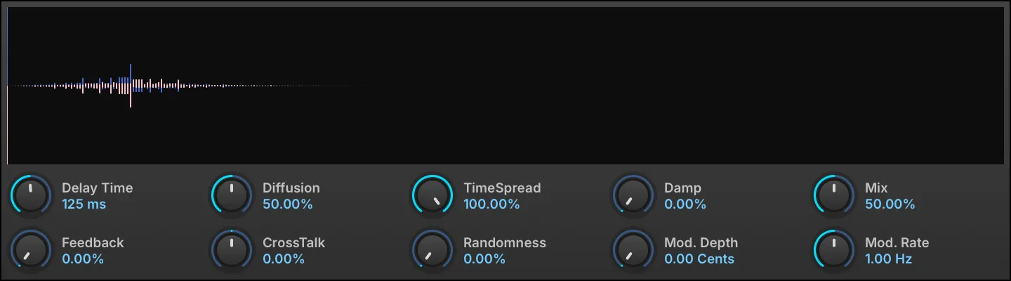
Diffuse Delay is an effect capable of morphing continuously from a pure single tap delay to a very long, dense, and lush bloom of echoes. Fantastic for scrambling voices or other instruments into an ambient wash of echoes.
DELAY TIME (0.01–1 s) sets the length of delay, in seconds (shown in ms below 1 s), or in bars/beats when tempo-synced.
DIFFUSION (0–100 %) sets the amount of diffusion (echo density), and TIMESPREAD (0–100 %) sets the time spread of the diffusion.
FEEDBACK (0–100 %) chooses the percentage of signal fed back into the module.
DAMP (0–100 %) sets the amount of damping factor for feedback loops.
RANDOMNESS (0–50 %) adds random variation to the diffusion pattern for a less regular, more natural echo texture.
NOTE: Diffuse Delay will re-calculate the time factor for producing the effect. So manipulating the Delay Time and TimeSpread controls will cut the effect for a moment. This means these parameters are not usable for modulation or automation.
CROSSTALK (−100–100 %) sets the crosstalk amount between the left and right channels of the feedback loop.
MIX (0–100 %) sets the balance between the dry (unaffected) and wet (affected) signal sent to the module’s output.
MOD. DEPTH (0–20 cents) chooses a detune amount for the delay taps, and MOD. RATE (0.1–10 Hz) sets the speed of modulation.
Dual Delay X
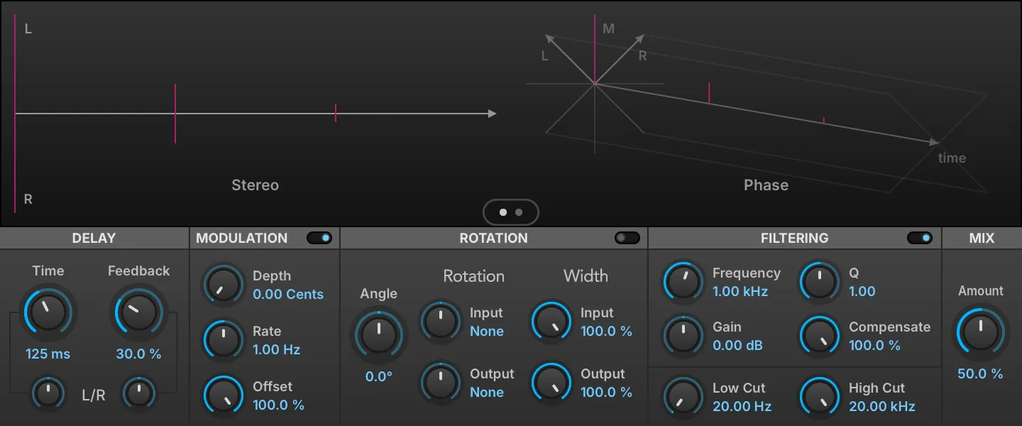
A versatile delay module with discrete channel controls for creating time-based effects. A sophisticated display visualizes changes to time, stereo and phase. Dual Delay X features built-in dispersion, diffusion, digital grit and tape saturation for a more polished sound out of the box. NOTE: Dual Delay is still available as Legacy FX.
Click the switch to toggle between Rotation and Reflection mode, applied to the stereo feedback.
Click the Switch to enable the Filtering section. A peak EQ located in the feedback loop.
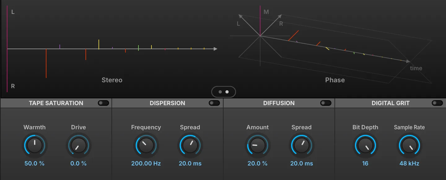
Click the Switch to toggle between main and feedback shaping controls.
TIME (0.001–5 s) sets the length of delay, in ms or bars/beats (if tempo-synced). FEEDBACK (0–100 %) chooses the percentage of signal fed back into the module. Both Time and Feedback have L/R controls that shorten one channel relative to the other: the display reads Same at the center, and L x or R x followed by a multiplier (0.10–1.00) applied to that channel only. Use 0.66 for dotted, 0.5 for half and 0.33 for triplet.
Modulation
Click the Switch to enable the Modulation section. DEPTH (0–20 cents) chooses a detune amount for the delay taps, and RATE (0.1–10 Hz) sets the speed of modulation. OFFSET (0–100 %) adjusts the phase offset of the delay line LFO.
Rotation/Reflection
ANGLE (−180 to 180) sets the rotation angle applied to the stereo feedback path.
The ROTATION section rotates the stereo field of the INPUT (−45 to 45°) and OUTPUT (−45 to 45°) signals; +45° on the input performs an L/R to M/S conversion, and −45° on the output converts back.
The WIDTH section adjusts the stereo spread of the signal INPUT (0–100 %) to the effect, and the spread of the OUTPUT (0–100 %) signal.
Filtering
FREQUENCY (20–20,000 Hz) sets the EQ frequency. GAIN (−20–20 dB) sets the EQ gain amount (+/-). Q (0.1–10) sets the filter’s bandwidth. COMPENSATE (0–100 %) sets the amount of gain reduction for EQ to avoid feedback instability. LOW CUT (20–4,000 Hz) rolls off lower frequencies, and HIGH CUT (1,000–20,000 Hz) rolls off higher frequencies. The filters affect only the wet signal; the dry signal is not filtered.
Tape Saturation
Click the Switch to enable the section. WARMTH (0–100 %) sets the amount of the pre-emphasis before saturation, and DRIVE (0–100 %) sets the saturation amount.
Dispersion
Click the Switch to enable the section. FREQUENCY (0–20,000 Hz) sets the dispersion frequency, and SPREAD (1–100 ms) sets the dispersion time in ms.
Diffusion
Click the Switch to enable the section. AMOUNT (0–100 %) sets the diffusion amount, and SPREAD (1–100 ms) sets the diffusion time in ms.
Digital Grit
Click the Switch to enable the section. BIT DEPTH (4–16) sets the bit reduction, and SAMPLE RATE sets the sample rate reduction.
Mix
AMOUNT knob sets the balance between the dry (unaffected) and wet (affected) signal sent to the module’s output.
Display
The display shows a visual representation of how the controls will affect the STEREO and PHASE output of the module.
Tape Echo

A recreation of the famous 70s tape delay.
RATE sets the rate of the delay repeats, INTENSITY (0–200 %) chooses the percentage of signal fed back into the module.
Mode
The central MODE knob selects between delay, delay + reverb, or reverb only modes.
The numeric indicators (1, 2, 3, and combinations) represent which of three discrete delay heads will be utilized.
The DELAY TIMES (0.05–0.5 s) for each head can be seen and modified via the I, II, III number boxes on the right.
The STOP button activates a tape stop effect.
REVERB GAIN (0–100 %) sets the reverb volume.
Filter
The filters shape the delayed signal only; neither the dry signal nor the reverb is filtered. BASS (−10 to 10) boosts or cuts the low frequencies, and TREBLE (−10 to 10) boosts or cuts the high frequencies.
Output
MIX (0–100 %) knob sets the balance between the dry (unaffected) and wet (affected) signal sent to the module’s output.
Track Delay

A simple time-shifting of the input using a delay.
DELAY TIME (0–5 s) sets the length of delay, in μs, ms and seconds or bars/beats (if tempo-synced).
Velvet Delay
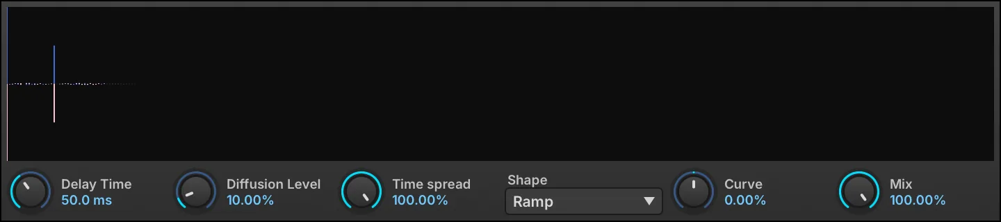
Velvet Delay is another take on morphing from a single tap delay to a smooth aura of echoes. Compared to Diffuse Delay, the emphasis is less on maximal diffuseness, but more on the smoothness of the pre and post echoes and precise control of the ratio between specular and diffuse reflections.
DELAY TIME (0.001–1 s) sets the length of delay, in seconds (shown in ms below 1 s).
DIFFUSION LEVEL (0–90 %) sets the amount of diffusion (echo density), and TIME SPREAD (10–100 %) sets the time spread of the diffusion.
SHAPE chooses the echo shape — Ramp (the default), Uniform, Exp, Ramp down, Parabolic, Inv. Parabolic or Parametric — and CURVE (−100–100 %) bends the Parametric shape toward a concave or convex ramp; it has no effect on the other six shapes.
MIX (0–100 %) sets the balance between the dry (unaffected) and wet (affected) signal sent to the module’s output.
Reverb
Bloom
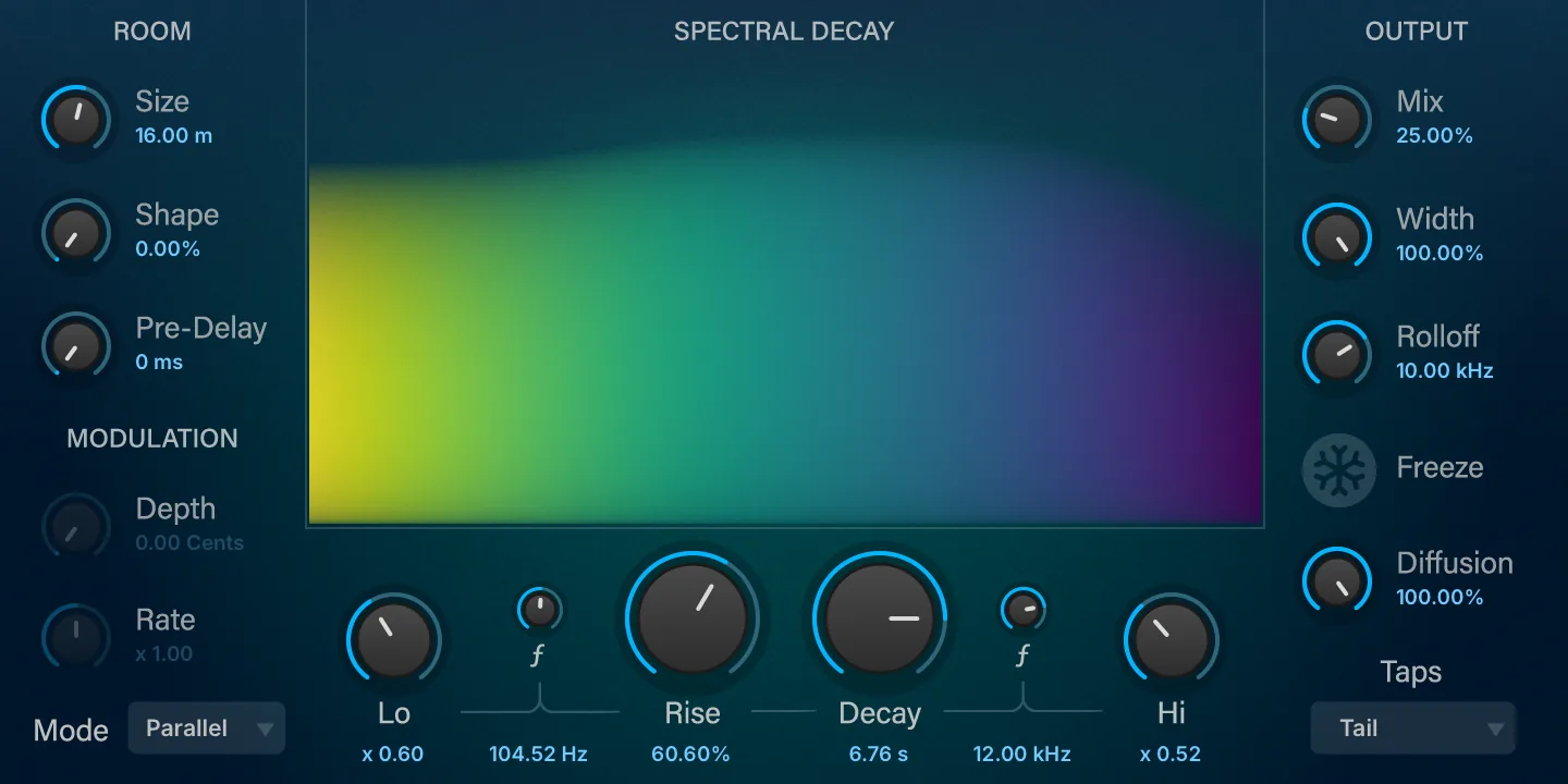
A reverb that swells into existence, building rich ambience after your initial sound. Shape the rise, depth, and decay to create lush soundscapes, evolving textures, and immersive atmospheres unique to Bloom.
The central DECAY (0.1–10) parameter scales the duration of the reverb decay; it is a multiplier, and the decay time it displays also follows Size. Low and Hi frequency bands can further tailor the decay response across frequencies. Set the decay ratio for each band (relative to the main Decay time) with LO (0.1–10) and HI (0.1–10), and the crossover frequency of each band with the small ƒ knob beside it (10–1,000 Hz for Lo, 2,000–20,000 Hz for Hi). RISE (0–100 %) controls the amount of rise time as a percentage of the current decay time; it applies in Parallel and Serial modes only, and has no effect in Single.
Room
SIZE (4–50) sets the mean room dimension in meters with continuous control (from tiny rooms to huge halls). SHAPE (0–100 %) sets the delay distribution and distortion of the room, from 0 % (highest echo density) to 100 % (highest spectral mode density).
PRE DELAY (0–250 ms) sets the amount of delay before the wet signal is heard.
Modulation
DEPTH (0–20 cents) chooses the depth of the decay modulation, in cents.
RATE (0.1–10) chooses a relative ratio for each delay line. Modulation is disabled in Parallel mode: Depth and Rate act in Single and Serial only.
Mode
Select the processing mode:
-
SINGLE: a single reverb engine, with no rise time (Rise has no effect).
-
PARALLEL: Rise time is obtained by running two slightly detuned reverb engines in parallel.
-
SERIAL: Rise time is obtained by running two slightly detuned reverb engines in sequence.
Output
MIX (0–100 %) sets the balance between the dry (unaffected) and wet (affected) signal sent to the module’s output. WIDTH (0–100 %) adjusts the stereo spread of the module’s output. ROLLOFF (2,000–20,000 Hz) sets the cutoff frequency of an overall low-pass filter to adjust the brightness of the wet signal. Enabling FREEZE will hold the current decay infinitely, until Freeze is disabled.
DIFFUSION (0–100 %) controls the amount of diffusion applied; lower amounts leave more distinct, discrete echoes, while higher amounts build a denser, smoother, more reverb-like tail.
Taps
Select the shape of the impulse response and early reflections.
Diffusion

Diffusion spreads the signal over time, creating a simple yet versatile decay with reverb-like results.
The display is the effect’s impulse response rather than its frequency response, which is flat when the effect is fully wet. It is fed opposite impulses on the two channels, so the stereo decorrelation the allpass delays produce is visible as the two traces diverge.
The DIFFUSION (0–100 %) control sets the amount of diffusion applied.
DIFFUSION START (0.1–20 ms) chooses the time delay until diffusion begins to be applied.
MIX (0–100 %) sets the balance between the dry (unaffected) and wet (affected) signal sent to the module’s output.
IReverb
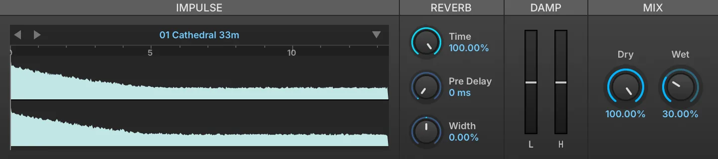
IReverb is a convolution reverb. Given an impulse response for a physical space or a piece of gear, IReverb can accurately reproduce what the input source would sound like if it were actually in that space or played through that piece of hardware.
If there is audio passing through the IReverb while parameters are being adjusted, the dry signal will be heard momentarily. This is because convolution is a processor-intensive effect and briefly muting the processed signal is necessary to avoid pops/clicks or other artifacts.
To load an IMPULSE RESPONSE, drag and drop an audio file to the sample area, or load one of the factory presets.
Reverb
TIME (10–100 %) sets the duration of the wet signal, specified as a percentage of the impulse response’s duration. PRE DELAY (0–100 ms) sets the amount of delay before the wet signal is heard.
Damp
LOW DAMP (−100–100 %) and HIGH DAMP (−100–100 %) reshape how the low or high frequencies evolve along the tail rather than filtering the output: positive values fade the band out over the decay, negative values fade it in.
Mix
DRY (0–100 %) and WET (0–100 %) knobs set the balance between the dry (unaffected) and wet (affected) signal sent to the module’s output.
Impulse Files
To save the currently loaded impulse, choose SAVE IMPULSE to save the current file or SAVE IMPULSE AS to save as a new file.
WIDTH (−100–100 %) adjusts the stereo width of the impulse response. At negative values, the stereo image is narrowed, collapsing to mono at −100 %.
SparkVerb
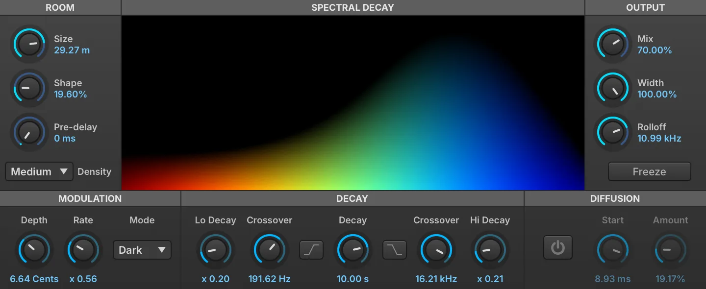
SparkVerb is a unique and versatile algorithmic reverb, centered around a frequency-based spectral display. The sound can be shaped with separate frequency bands, or adjusted globally.
The central DECAY (0.1–10) parameter scales the duration of the reverb decay; it is a multiplier, and the decay time it displays also follows Room Size. Low and Hi frequency bands can further tailor the decay response across frequencies. Choose the frequency for each band with LO XOVER (10–1,000 Hz) and HI XOVER (2,000–20,000 Hz), and set the decay ratio (relative to the main Decay time) with LO DECAY (0.1–10) and HI DECAY (0.1–10). If you would rather cut the Low or Hi bands instead, use DECAY LOW-CUT and DECAY HI-CUT.
Room
ROOM SIZE sets the size of the simulated space, from small rooms (4 meters) to very large rooms (50 meters). SHAPE (0–100 %) sets the delay distribution and distortion of the room, from 0 % (highest echo density) to 100 % (highest spectral mode density). PRE DELAY (0–100 ms) sets the amount of delay before the wet signal is heard. DENSITY changes how dense the reflections will be; lower values will be more like distinct echoes.
Modulation
DEPTH (0–20 cents) chooses the depth of the decay modulation, in cents. RATE (0.25–4) chooses a relative ratio, from 1/4 to 4x, for each delay line. MODE sets the modulation interpolation style; choose from Dark (default; some high-frequency decay damping), Lo-Fi (more high frequency diffusion), or Bright (more precise high-frequency response, but more processor intensive).
Diffusion
DIFFUSION ON/OFF toggles the short-term diffusion option. When enabled, DIFFUSION START (1–10 ms) sets the delay time until the diffusion is heard, and AMOUNT (0–100 %) sets how much diffusion will be applied.
Output
MIX (0–100 %) sets the balance between the dry (unaffected) and wet (affected) signal sent to the module’s output. WIDTH (0–100 %) adjusts the stereo spread of the module’s output. ROLLOFF (2,000–20,000 Hz) sets the cutoff frequency of an overall low-pass filter to adjust the brightness of the wet signal. Enabling FREEZE will hold the current decay infinitely, until Freeze is disabled.
Modulation
Analog Chorus

Analog Chorus is a chorus module that is inspired by a popular analog effects pedal.
SPEED (0.1–10 Hz) sets the speed of the modulation, WIDTH (0–6) adjusts the width of the stereo spread, and INTENSITY (0–6) sets the depth of the effect.
TRANSIENT ENHANCEMENT (0–10) adjusts how much transients are affected by the module. Higher values allow for more prominent, unmodulated transients.
Analog Flanger

Analog Flanger is a flanger module that is inspired by a popular analog effects pedal.
SPEED (0.1–10 Hz) sets the speed of the modulation, and INTENSITY (0–6) sets the depth of the effect. WIDTH (0–6) adjusts the delay times and modulation depth to increase the stereo width of the effect.
TRANSIENT ENHANCEMENT (0–10) adjusts how much transients are affected by the module. Higher values allow for more prominent, unmodulated transients.
Analog BBD Chorus
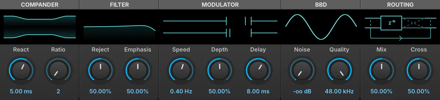
Analog BBD Chorus runs the same bucket-brigade line as the delay at chorus lengths, in the spirit of the 80s studio rack units. Its modulation is deliberately anti-phase across the two channels: the delay time of the pair moves apart and back together rather than up and down as one, which widens the image without the warble a shared sweep produces.
As with the delay, each section’s display can be dragged — horizontally for the left knob, vertically for the right.
Compander
REACT (1–50 ms) and RATIO (2–6) set the speed and the ratio of the compander bracketing the chain, exactly as they do on the delay.
Filter
REJECT (0–100 %) sets the anti-alias filter relative to the BBD’s own clock rather than in hertz: at 0 % the corner sits at the clock rate, at 100 % two octaves below it, never above 22 kHz, so the filter follows whatever Quality is set to. EMPHASIS (0–100 %) sets its resonance. The display plots the curve against a fraction of the clock’s Nyquist rather than a frequency axis, for the same reason.
Modulator
SPEED (0.05–2 Hz) sets the rate of the triangle modulator and DEPTH (0–100 %) how far it swings the clock, up to ±30 % of its rate. DELAY (1–30 ms) sets the delay the modulation moves around. The display animates the two channels as markers traveling in opposite directions along the delay axis, in real time.
BBD
QUALITY (1–48 kHz) sets the clock rate the brigade runs at, and the number of stages follows from it. Lowering it coarsens the sampling audibly — the display draws the staircase getting rougher. NOISE sets the level of the chip’s own noise.
Routing
MIX (0–100 %) sets the balance between the dry and processed signal. CROSS (0–100 %) adds each channel’s wet signal, inverted and low-shelved, into the other channel’s output: a width control in the manner of the Dimension units rather than a channel swap, canceling the middle of the wet signal as it is raised while leaving the bass in place.
Ensemble 505

Ensemble 505 is an ensemble chorus effect, inspired by the ensemble effect section of a popular synth.
MODE chooses the style of ensemble: I is the plain ensemble, II adds a light fast secondary modulation on two of the four delay lines, and III instead adds feedback to the delay lines, for the most pronounced effect. TONE (3,000–10,000 Hz) sets the cutoff of the low-pass filtering applied along the ensemble path, both to the signal entering the delay lines and to each delay line output.
MIX (0–100 %) sets the balance between the module’s input path and the ensemble output. The input path is not the untouched signal: it is summed to mono and low-pass-filtered by TONE before the blend, so at 0 % the module still outputs a mono, filtered version of the input.
Flanger

Flanger is a classic flanger effect, where the input signal is delayed with a variable time delay and fed back onto itself.
SPEED (0.01–10 Hz) sets the speed of the modulation (in Hz, or bars/beats if tempo-synced).
DELAY TIME (0–20 ms) sets the base delay the modulation sweeps around. Note: the value display currently reads 50 times too high (for example, 200 ms means 4 ms). DEPTH (0–100 %) sets the depth of the effect.
FEEDBACK (0–100 %) sets the percentage of signal fed back into the module.
MIX (0–100 %) sets the level of the flanged signal added to the module’s output. It is not a dry/wet balance: the dry signal always passes at full level, so raising Mix adds the effect on top of it rather than replacing it.
Freq Shifter
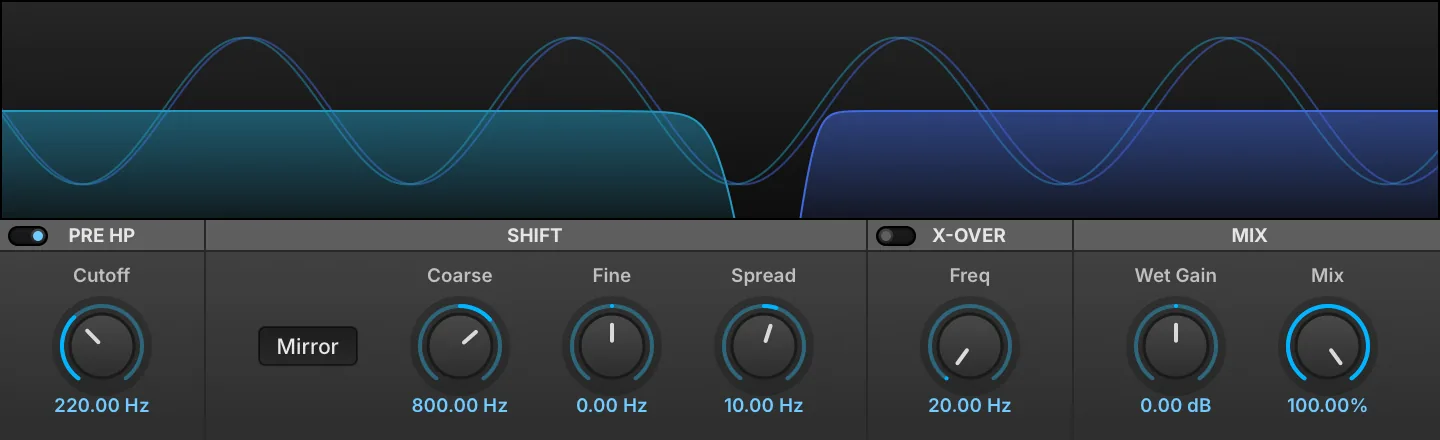
Freq Shifter is a linear frequency shifter effect. Shifts all frequencies in the spectrum by a set amount (Hz) for interesting morphing effects, widening, sound thickening and repitching inharmonic sounds like drums.
Pre HP
Click the Switch to enable the section.
CUTOFF (20–20,000 Hz) sets the cutoff frequency of the pre-high-pass -24 dB/oct Butterworth filter, which gets rid of the low end when the shift is too high.
Shift
MIRROR adds extra content in the low end when enabled. With a positive shift, partials below the shift amount also appear mirrored at (shift − frequency). With a negative shift, partials pushed below 0 Hz fold back as mirrored low frequencies instead of being removed. With MIRROR off, these components are discarded. NOTE: with MIRROR off, extreme positive shifts produce aliasing.
COARSE / FINE shifts the spectrum up or down by a constant frequency in Hz such that harmonic sounds become inharmonic.
SPREAD (−200–200 Hz) adds a shift difference between the channels. Even a slight difference can be used to get a full, wide stereo effect.
X-over
Click the Switch to enable the section. FREQ (20–20,000 Hz) sets the split frequency of a -24 dB/oct crossover filter to allow preservation of the original low-frequency content.
Mix
WET GAIN (−12–12 dB) sets the gain of the wet signal. MIX (0–100 %) sets the dry/wet amount.
Granulizer
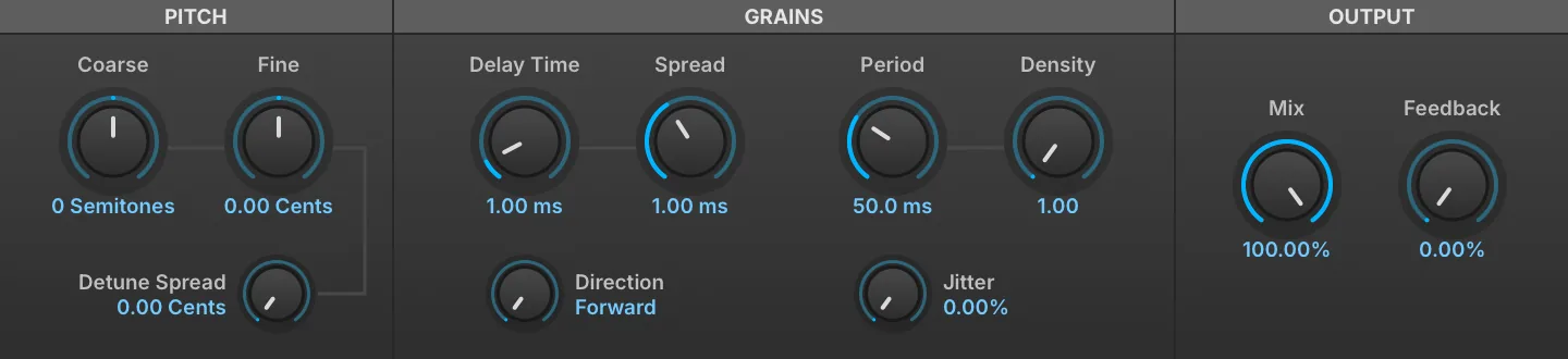
Granulizer can be thought of as the effect equivalent to Falcon’s granular oscillator, and is exceptional for creating pads, textures, and ambiance. Instead of splicing grains of sound taken from audio files, grains are extracted directly from audio in real time. It is possible to shape sound in multiple ways for kaleidoscopic sound deconstruction and reconstruction.
COARSE / FINE shifts the grain pitch in semitones and cents. DETUNE SPREAD (0–100 cents) adds a detune effect to each grain.
Grains
DELAY TIME (0–2 s) sets how far back in the captured audio the grains are read, in seconds, and SPREAD (0–0.005 s) adds the variation of the delay time. DIRECTION sets the direction of scrubbing: Forward, Backward, Alternate and Random.
PERIOD (0.01–2 s) sets the duration of the grains. DENSITY (1–10) determines how many grains overlap at any time, two grains at 1.00 and up to twenty at 10.00. Raising it thickens the overlap, with a harmonic result similar to a chorus or sometimes a ring modulator. JITTER (0–100 %) varies the consistency of grain playback timing.
Output
MIX (0–100 %) sets the dry/wet amount. FEEDBACK (0–100 %) sets the percentage of signal fed back into the module.
DENSITY COMPENSATION (0–100 %) sets how the gain change caused by overlapping grains is compensated, from a DC-summing assumption at 0 % to a white-noise-summing one at 100 %. It is not on the module’s front panel; reach it from the parameter list or as a modulation target.
Phasor
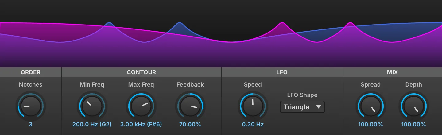
Phasor is a variable 12-order automatic phaser effect.
NOTCHES (1–12) changes the number of filters in sequence which correlates to the number of peaks and valleys you see displayed in the visualizer.
Mix
SPREAD (0–100 %) emphasizes the stereo effect. DEPTH (0–100 %) sets the wet/dry mix amount.
Contour
In Phasor an LFO sweeps between two variable frequencies, these are controlled with MIN FREQ (20–20,000 Hz) and MAX FREQ (20–20,000 Hz).
FEEDBACK (−99–99 %) controls the amount of the effected signal reinjected.
LFO
SPEED sets the speed of the LFO, which defaults to a free-running frequency between 0.01 Hz and 10.00 Hz.
Toggling the TEMPO SYNC icon in the header allows the LFO to be synced to the host clock and set between 1/64 tri and 32x.
LFO SHAPE controls the shape of the LFO which can be set to TRIANGLE, SINE, S&H or RANDOM.
Rotary
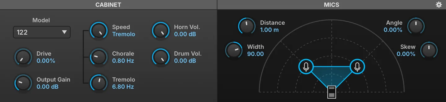
Rotary is a highly customizable speaker emulation effect modeled after the classic two-way rotating designs created for electric organs in the 1940s.
MODEL changes the cabinet type. DRIVE (0–100 %) sets the amount of overdrive in the cabinet circuit. GAIN (0–4) controls the amount of output gain.
Seven cabinets are available: 122, 145, 30, 722, 760, 950 and 16, each with its own enclosure dimensions.
SPEED sets the rotary style: BRAKE = none, CHORALE = slow speeds, TREMOLO = fast speeds.
Chorale and Tremolo speeds are controllable with the CHORALE (0.1–3 Hz) and TREMOLO (3–10 Hz) knobs below.
Mics
DISTANCE (0.1–2 m) sets the distance of the mics to the cabinet. ANGLE (−100–100 %) rotates the pair of mics around the cabinet, away from the front axis.
WIDTH (−180 to 180) sets the angular separation of the two mics. SKEW (−100–100 %) sets the disparity in distance between mics and cabinet. If set high, one mic will be close and the other will be far from the speaker.
BACKPANEL (COGWHEEL ICON) opens the settings to access the back panel controls.
HORN VOL (0–1) adjusts the rotating horn level. DRUM VOL (0–1) adjusts the rotating drum level.
Back Panel
-
Horn: standard directivity with deflector.
-
Omni: No AM
-
Cardio: Classic polar pattern (sound cancellation when horn is off-axis).
-
SoftCardio: Softer version of cardioid (with no off-axis cancellation).
-
Unipolar: heavy pulsating tone (pronounced AM).
-
Drum: directivity with fewer side lobes - less wide sound (usable on horn).
-
Drum Cardio: standard drum directivity (usable on horn).
-
Drum Cardio 2: More pronounced off-phase side lobes (drum exclusive).
-
Drum Cardio 3: Most pronounced off-phase side lobes (drum exclusive).
Settings
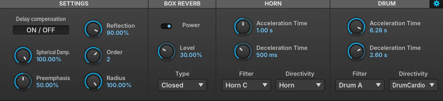
DELAY COMPENSATION removes latency caused by mic distance.
SPHERICAL DAMPENING (0–100 %) controls the amount of attenuation that is applied to reflections with propagation distance.
PREEMPHASIS (0–100 %) controls the amount of preemphasis that is applied before amplifier drive. REFLECTION (0–100 %) controls how reflective the cabinet walls are, higher values giving stronger internal reflections.
ORDER (0–3) controls the order of ray traced early reflections for the horn; the drum is always limited to first order. RADIUS (0–100 %) changes the length of horn and drum speakers.
Box Reverb
POWER enables diffusion. LEVEL (0–100 %) sets the amount of diffusion. TYPE selects the enclosure used for the diffusion: Open or Closed back.
Horn
ACCELERATION TIME (0.1–10 s) sets the horn acceleration time. DECELERATION TIME (0.1–10 s) sets the horn deceleration time. FILTER sets the horn frequency response. DIRECTIVITY chooses the horn directivity type.
The horn FILTER offers Off, Horn A, Horn B and Horn C.
Drum
ACCELERATION TIME (0.1–10 s) sets the drum acceleration time. DECELERATION TIME (0.1–10 s) sets the drum deceleration time. FILTER sets the drum frequency response. DIRECTIVITY chooses the drum directivity type.
The drum FILTER offers Off and Drum A.
Thorus
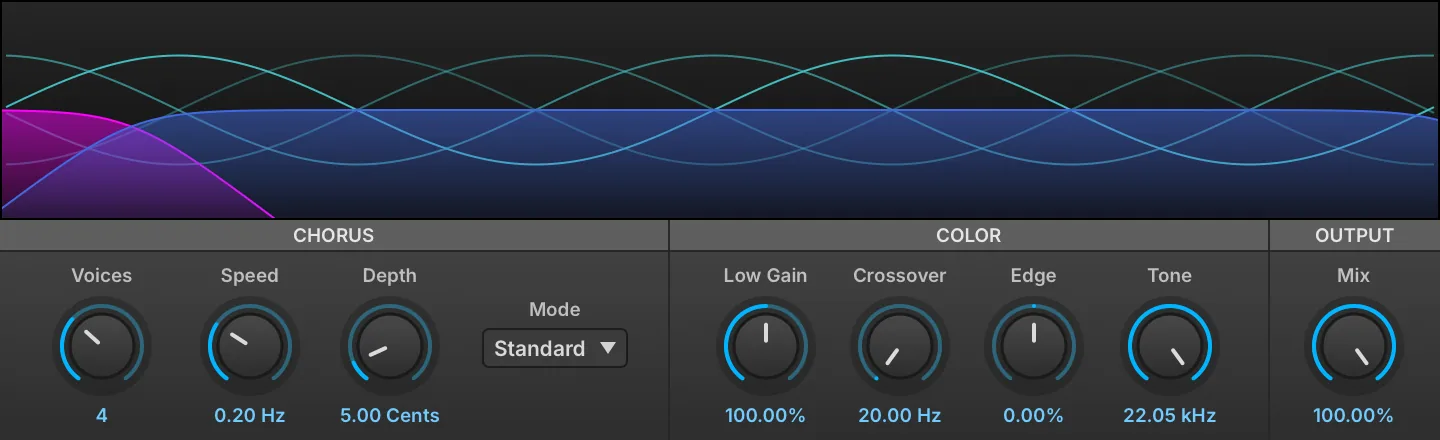
Thorus is a variable 8-voice chorus that provides an exceptionally clear effect and a number of useful color controls.
VOICES sets the number of chorus voices utilized from 2–8.
SPEED sets the chorus frequency from 0.1 Hz to 1.0 Hz. DEPTH sets the pitch modulation depth from 1 to 40 cents.
MODE influences the perceived stereo effect and can be set to either Standard or Wide.
Color
CROSSOVER (20–5,000 Hz) sets the crossover frequency between the Low (pass-through) signal and the High (chorused) signal. LOW GAIN (0–200 %) controls the level of the low (pass-through) signal.
EDGE (−100–100 %) controls the feedback amount of the High (chorused) signal. TONE (2,000–22,050 Hz) controls the frequency of the low-pass filter.
Output
MIX (0–100 %) controls the wet/dry mix amount of the effect.
TRIM (−12–0 dB) attenuates the module’s output, to compensate for the level the chorus adds. It is not on the module’s front panel; reach it from the parameter list or as a modulation target.
Filter
Analog Filter

Analog Filter is a multimode filter inspired by the filter section found on a popular American analog synth.
MODE chooses the type of filter: low-pass (LP), high-pass (HP), or band-pass (BP).
CUTOFF (20–20,000 Hz) sets the frequency for the filter; the note name corresponding to the frequency is also displayed, for example, 2.00 kHz (B5).
RESONANCE (0–100 %) adjusts how much the cutoff frequency is emphasized.
KEY TRACKING (0–100 %) changes how the cutoff frequency is adjusted relative to the note played.
Biquad Filter

The classic Swiss Army knife multimode filter.
MODE chooses the type of filter: high-pass (HP), low-pass (LP), band-pass (BP), or notch.
CUTOFF (20–20,000 Hz) sets the frequency for the filter; the note name corresponding to the frequency is also displayed, for example, 2.00 kHz (B5).
RESONANCE (0–100 %) adjusts how much the cutoff frequency is emphasized.
KEY TRACKING (0–100 %) changes how the cutoff frequency is adjusted relative to the note played.
Brickwall Filter

Brickwall Filter is a filter with a steep slope, from 24 dB/oct up to 96 dB/oct, for “brickwall” filtering beyond the cutoff frequency.
CUTOFF (20–20,000 Hz) sets the frequency for the filter; the note name corresponding to the frequency is also displayed, for example, 2.00 kHz (B5).
TYPE chooses the type of filter: low-pass (LP) or high-pass (HP).
SLOPE sets how sharply the filter slopes downward at the cutoff frequency, in dB per octave: 24, 48 or 96 dB/oct (96 dB/oct by default).
SOFT BYPASS lets the signal through unfiltered, crossfading over 100 ms when switched. This is an ideal way to bypass the effect while playing, as the regular bypass can pop or click if switched during playback.
Comb Filter

A classic comb filter, where a time delayed version of the signal is fed back into itself and added or subtracted. This results in unique frequency peaks and valleys where the phases of the signals combine or cancel each other out.
MODE chooses the type of comb filter applied: Plus (frequencies are added) or Minus (frequencies are subtracted).
CUTOFF (20–20,000 Hz) sets the frequency for the filter; the note name corresponding to the frequency is also displayed, for example, 2.00 kHz (B5).
RESONANCE (0–100 %) adjusts how much the cutoff frequency is emphasized.
KEY TRACKING (0–100 %) changes how the cutoff frequency is adjusted relative to the note played.
ALGORITHM chooses how the comb is rendered. Modern, the default, interpolates the delay with an allpass filter, smooths changes to the delay and the feedback, and normalizes the level, so the output stays bounded however the filter is modulated. Classic is the original comb sound. Programs saved with earlier versions load in Classic, so they keep their sound.
Crossover Filter

Crossover Filter has a selectable filter type and variable crossover frequencies for the affected band.
When Low Pass is chosen, only the Low-Mid knob can be adjusted; the Mid-High Freq knob is disabled.
Likewise, when High Pass is chosen, only the Mid-High knob can be adjusted.
Both knobs can be adjusted when Band Pass is chosen.
TYPE chooses the type of filter: low-pass (LP), high-pass (HP), or band-pass (BP).
LOW-MID FREQ (20–20,000 Hz) and MID-HIGH FREQ (20–20,000 Hz) set the frequency boundaries for the crossover.
Digital Filter

Digital Filter is a multi-mode filter with variable slope ranging from 6 to 96 dB/oct, spread and key tracking.
MODE sets the filter mode and filter slope. Click the upper button to switch the filter mode: low-pass, high-pass, band-pass, notch, low-shelf, high-shelf and peak, and the lower button to set the filter slope: 6, 12, 18, 24, 36, 48, 72 or 96 dB/oct.
FREQUENCY (10–22,000 Hz) sets the frequency for the filter.
KEY TRACKING (−100–100 %) changes how the cutoff frequency is adjusted relative to the note played. SPREAD (−48–48 st) emphasizes the stereo effect.
Q adjusts the filter resonance, and has no effect on the 6 dB/oct slope. GAIN (−30–30 dB) sets the boost or cut applied by the low-shelf, high-shelf and peak modes, and is inactive for the other modes.
BANDWIDTH (0.01–10 oct) sets the width of the band, and applies to the band-pass, notch and peak modes only.
Formant Crusher

A screaming lo-fi take on formant filtering, (ab)using a resonant filter and a bitcrusher to generate vocal formants; a perfect fit to spice up your talking basses!
FORMANT (−100–100 %) shifts the formant frequencies up or down by up to one octave.
BITE (0–100 %) hardens the crusher, fading its output from smoothed steps to raw sample and hold.
Q (10–20) sets the filter’s width.
Shape
Two vowel sounds can be chosen for the filter, set via FILTER A and FILTER B, while the blend of the two is controlled via MORPH (0–100 %).
Mix
AMOUNT sets the balance between the dry (unaffected) and wet (affected) signal sent to the module’s output.
LPG

LPG is a low-pass gate built on a model of the vactrol cell used in the classic West Coast designs. A single control voltage lights the cell’s lamp, and the photoresistor it illuminates opens the filter and raises the level together, with the slow, uneven attack and the long relaxation of the component itself. Notes taper into silence rather than being cut off, which is where the plucked, resonant character of the circuit comes from.
MODE chooses what the cell drives: Lowpass filters without touching the level, VCA changes the level without touching the tone, and Both opens brightness and level together, as the original circuit does.
RESO (0–100 %) emphasizes the moving filter corner. It applies to the filter alone, and so is available in Lowpass mode only.
GATE (0–100 %) opens the gate by hand. It is the control voltage the cell sees, so it raises brightness and level together according to the Mode setting, and it responds with the lag of the component rather than instantly.
SENS (0–5 V) scales the control voltage reaching the cell at a fully open gate, setting how far the gate travels and how hard it drives the cell.
AUTO drives the gate from note on and note off, in place of the Gate control, which is then unavailable. This is what turns the module into a per-note gate rather than a manual or modulated one. It follows note events, so it only does anything where the effect sees them: on a keygroup insert, which runs once per voice. Placed higher in the hierarchy — on a layer, program or part — there are no notes for it to follow and the gate does not move.
VEL scales that automatic gate by the velocity of the note instead of opening it fully, so a harder note opens the gate further. It is available only with Auto enabled.
The display at the right traces a single gate event as the cell produces it, its height standing for level and its color for brightness — a magnitude response cannot show what a low-pass gate does, since the filter and the level move together. The CV bar between Gate and Sens reads the control voltage reaching the cell, in volts.
Ladder

Our take on the classic East Coast low-pass filter sound, capable of everything from smooth tones to ripping sweeps.
RESONANCE TRIM (0–50 %) adds feedback on top of the Resonance setting, up to self-oscillation.
GAIN COMPENSATION (0–100 %) makes up the level lost as resonance increases.
OVERSAMPLING TYPE chooses the sample rate conversion used: Simple, or Precise for cleaner filtering at a higher CPU cost.
CUTOFF (20–20,000 Hz) sets the frequency for the filter; the note name corresponding to the frequency is also displayed, for example, 2.00 kHz (B5).
RESONANCE (0–100 %) adjusts how much the cutoff frequency is emphasized.
VOLTAGE REF (0.01–1 V) sets the level driven into the transistor ladder; higher values saturate earlier.
SCOPE shows the output (blue line) and input (pink square wave).
OVERSAMPLING (2–4) sets the internal oversampling factor; the filter always runs oversampled, and higher factors reduce aliasing at a higher CPU cost.
KEY TRACKING (0–100 %) changes how the cutoff frequency is adjusted relative to the note played.
Lowpass 12

Lowpass 12 is a 12 dB/octave low-pass filter.
CUTOFF (20–20,000 Hz) sets the frequency for the filter; the note name corresponding to the frequency is also displayed, for example, 2.00 kHz (B5).
RESONANCE (0–100 %) adjusts how much the cutoff frequency is emphasized.
KEY TRACKING (0–100 %) changes how the cutoff frequency is adjusted relative to the note played.
Lowpass 24

Lowpass 24 is a 24 dB/octave low-pass filter.
CUTOFF (20–20,000 Hz) sets the frequency for the filter; the note name corresponding to the frequency is also displayed, for example, 2.00 kHz (B5).
RESONANCE (0–100 %) adjusts how much the cutoff frequency is emphasized.
KEY TRACKING (0–100 %) changes how the cutoff frequency is adjusted relative to the note played.
One Pole

A gentle and very efficient 6 dB/octave low-pass or high-pass filter. The most efficient of all filters by far.
MODE chooses the type of filter: low-pass or high-pass.
CUTOFF (20–20,000 Hz) sets the frequency for the filter; the note name corresponding to the frequency is also displayed, for example, 2.00 kHz (B5).
KEY TRACKING (0–100 %) changes how the cutoff frequency is adjusted relative to the note played.
Phasor Filter
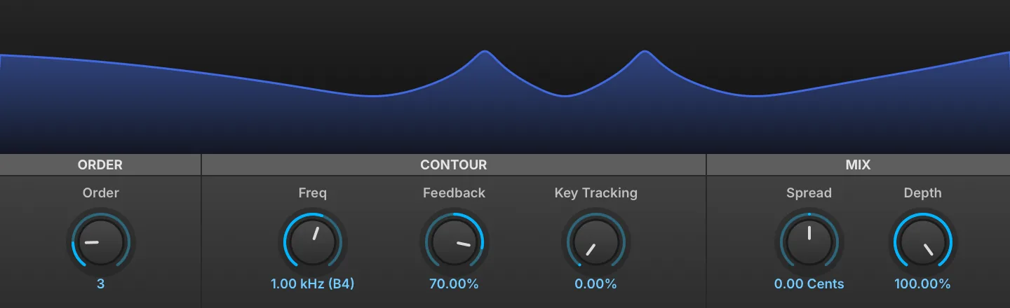
A manual version of the Phasor effect.
ORDER (1–12) changes the number of filters in sequence which correlates to the number of peaks and valleys you see displayed in the visualizer.
CONTOUR FREQ (20–20,000 Hz) sets the filter frequency.
FEEDBACK (−99–99 %) controls the amount of the effected signal reinjected.
KEY TRACKING (0–100 %) changes how the cutoff frequency is adjusted relative to the note played.
Mix
SPREAD (−12–12 st) emphasizes the stereo effect. DEPTH (0–100 %) controls the wet/dry mix amount.
CUTOFF MODE chooses how the notches are spaced: Default scales their spacing with the Order setting, Symmetric keeps them centered on the Freq setting.
Rez Filter

Rez Filter is inspired by the filter section found on a popular Japanese synth.
MODE chooses the type of filter: low-pass (LP), high-pass (HP), or band-pass (BP).
CUTOFF (20–20,000 Hz) sets the frequency for the filter; the note name corresponding to the frequency is also displayed, for example, 2.00 kHz (B5).
RESONANCE (0–100 %) adjusts how much the cutoff frequency is emphasized.
KEY TRACKING (0–100 %) changes how the cutoff frequency is adjusted relative to the note played.
SVF

SVF is a second-order (12 dB/oct) zero-delay-feedback state variable multimode filter with a built-in saturator.
FILTER MODE chooses the type of filter: low-pass (LP), high-pass (HP), band-pass (BP), peak, or notch.
CUTOFF (20–20,000 Hz) sets the frequency for the filter; the note name corresponding to the frequency is also displayed, for example, 2.00 kHz (B5). RESONANCE (0–100 %) adjusts how much the cutoff frequency is emphasized. KEY TRACKING (0–100 %) changes how the cutoff frequency is adjusted relative to the note played. DRIVE MODE chooses the style of overdrive, linear or soft.
Sallen-Key Filter

A circuit-modeled second-order single op-amp nonlinear Sallen-Key low-pass filter with controllable asymmetric clipping and power supply starvation.
CUTOFF (20–20,000 Hz) sets the frequency for the filter; the note name corresponding to the frequency is also displayed, for example, 1.00 kHz (B4).
RESONANCE (0–100 %) adjusts how much the cutoff frequency is emphasized.
KEY TRACKING (0–100 %) adjusts how much the cutoff frequency is adjusted relative to the note played.
SYMMETRY (−100–100 %) shifts the saturation symmetry between the two diodes, affecting the even/odd harmonic ratio.
RANGE (0–15) sets the saturation range.
OUTPUT chooses where the signal is tapped from the circuit: Soft takes it at the filter capacitor, Hard at the op-amp output, which tracks the clipping stage more closely.
Steiner Filter

Steiner Filter is a circuit-modeled multimode filter based on the Steiner-Parker design, whose input network feeds low-pass, band-pass and high-pass paths into a single saturating feedback loop. It offers thirteen fixed responses, from the usual second-order shapes to first-order and shelving variants, and five morphing ones: a free blend over the low-pass, band-pass and high-pass triangle, and four that sweep a single path across it.
CUTOFF (20–20,000 Hz) sets the frequency for the filter; the note name corresponding to the frequency is also displayed, for example, 2.00 kHz (B5).
RESONANCE (0–100 %) adjusts how much the cutoff frequency is emphasized; high settings make the filter ring and eventually self-oscillate.
KEY TRACKING (0–100 %) changes how the cutoff frequency is adjusted relative to the note played.
MODE chooses the response of the filter: LP, BP, HP, HP raw, Notch, Allpass, Peak, Low Shelf, High Shelf, LP1, HP1, LP Notch, HP Notch, Morph, LP-BP-HP, LP-HP, Tilt or LP1-HP1 (LP by default).
GAIN (−24–24 dB) sets the amount of boost or cut, and applies to the Peak, Low Shelf and High Shelf modes only.
DEPTH (−80–0 dB) sets the far-side gain in the LP Notch and HP Notch modes, the level the response settles to beyond the notch. At 0 dB the notch sits on the cutoff frequency; lower values move it away from the cutoff (upward in LP Notch, downward in HP Notch), and at −80 dB it lies 100 times away, so the filter behaves as a plain low-pass or high-pass.
MORPH LP, MORPH BP and MORPH HP (0–100 %) set the weight of each response in the blend used by the Morph mode; one control at full with the other two at zero reproduces that response exactly.
In Morph mode the display carries a triangle instead of the response alone, with low-pass at the bottom left, band-pass at the top and high-pass at the bottom right. Dragging the handle inside it sets the three weights at once, and the middle of each edge is marked with the response the blend reproduces there: LP1 between low-pass and band-pass, HP1 between band-pass and high-pass, and notch between low-pass and high-pass.
MORPH (0–100 %) is the position for the four one-dimensional morph modes, which sweep a single path rather than the whole triangle: LP-BP-HP travels from low-pass through band-pass to high-pass, LP-HP and LP1-HP1 run between their two endpoints at second and first order, and Tilt tips the spectrum from one side to the other, passing flat at 50 %.
SYMMETRY (−100–100 %) shifts the saturation symmetry between the two clipping thresholds, affecting the even/odd harmonic ratio.
RANGE (0–15) sets the headroom before the feedback path clips; lower values starve the circuit and distort sooner.
MODEL chooses between Ideal, a normalized response with no circuit coloration, and Circuit, which adds the coloration and makeup gain of the real input and feedback resistances (Circuit by default).
COUPLING (0–100 %) sets the ratio between the feedback and input resistances of the Circuit model, and has no effect on the Ideal model.
SOLVER chooses the integration scheme used for the saturating loop: Linear leaves the saturation out entirely, Linearly Implicit is the default, and Fixed Point and Newton trade CPU for accuracy.
UVI Filter

UVI Filter is a filter that is continuously adjustable between low-pass and high-pass modes.
CUTOFF sets the type and amount of filter. At the center position, no filter is applied. To the right of center, a high-pass filter is applied, and further to the right raises the cutoff frequency. Likewise, further left of center applies a low-pass filter and drops the cutoff frequency. The Q (0–1) control sets the filter’s shape.
MAPPING MODE sets the law used to map the CUTOFF control: use Standard for new patches, while presets saved by older versions of MachFive or UVI Player load with Legacy 1 or Legacy 2, which reproduce their original cutoff and Q curves.
VCF-20

Emulation of the MS-20 VCF filter (rev-2), single version with HP / LP morphing.
HP/LP MORPH (0–100 %) sets the balance between the high- and low-pass filters.
CUTOFF (20–20,000 Hz) sets the cutoff frequency of the filters.
PEAK (0–100 %) sets the resonance of the filter.
TRIM (0–100 %) adjusts the resonance shape.
VOLTAGE REF (0.5–5) sets the reference voltage of the unit.
KEY TRACKING (0–100 %) adjusts how the cutoff frequency is adjusted relative to the active note.
VCF-20 Dual
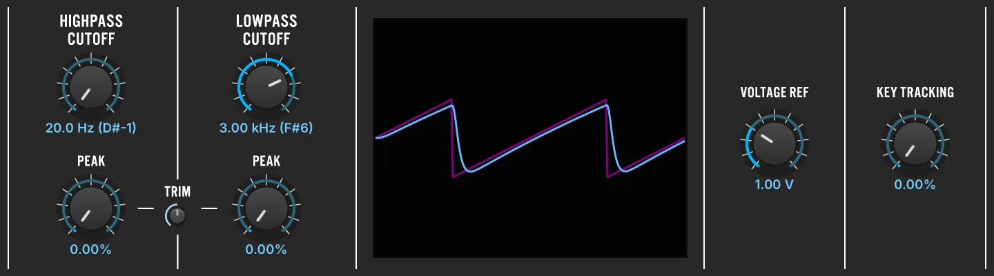
Emulation of the MS-20 VCF filter (rev-2), dual version with discrete LP and HP filters.
High Pass Filter
CUTOFF (20–20,000 Hz) sets the cutoff frequency of the filter. PEAK (0–100 %) sets the resonance of the filter.
Low Pass Filter
CUTOFF (20–20,000 Hz) sets the cutoff frequency of the filter. PEAK (0–100 %) sets the resonance of the filter.
TRIM (0–100 %) adjusts the resonance shape for both the high- and low-pass filters.
VOLTAGE REF (0.5–5) sets the reference voltage of the unit.
KEY TRACKING (0–100 %) adjusts how the cutoff frequency is adjusted relative to the active note.
VCF-4023

A virtual analog emulation of the ARP 4023 VCF circuit (as found in ARP Odyssey rev1) featuring OTA saturation and self-oscillation.
CUTOFF (20–20,000 Hz) sets the cutoff frequency of the filter.
RESONANCE (0–100 %) adjusts how much the cutoff frequency is emphasized.
VOLTAGE REF (1–15) sets the reference voltage of the unit.
SCOPE shows the output (blue line) and input (pink square wave).
HP FREQ (0–100 %) sets the cutoff frequency of the high-pass filter.
KEY TRACKING (0–100 %) adjusts the cutoff frequency relative to the active note.
OVERSAMPLE enables oversampling (2x/3x/4x) for the filter, providing higher precision at the cost of increased CPU utilization.
The parameter list holds three more: OTA SAT. and OPA SAT., both on by default, model the saturation of the two amplifier stages, and turning either off linearizes that stage. ALT. OUTPUT, off by default, takes the signal from the other tap of the filter chain.
Vowel Filter

Vowel Filter is a dual filter version of the classic talkbox effect.
MODE chooses the style of filter: low-pass (LP2), band-pass (BP2), or high-pass (HP2). Two vowel sounds can be chosen for the filter, set with FILTER A and FILTER B, and the blend of the two is controlled with MORPH (0–100 %). The Q (10–20) control sets the filter’s shape.
Set the number of formants with NUM FORMANTS (1–4); the formant frequencies are shifted higher or lower with the FORMANT (−100–100 %) control.
Vowels
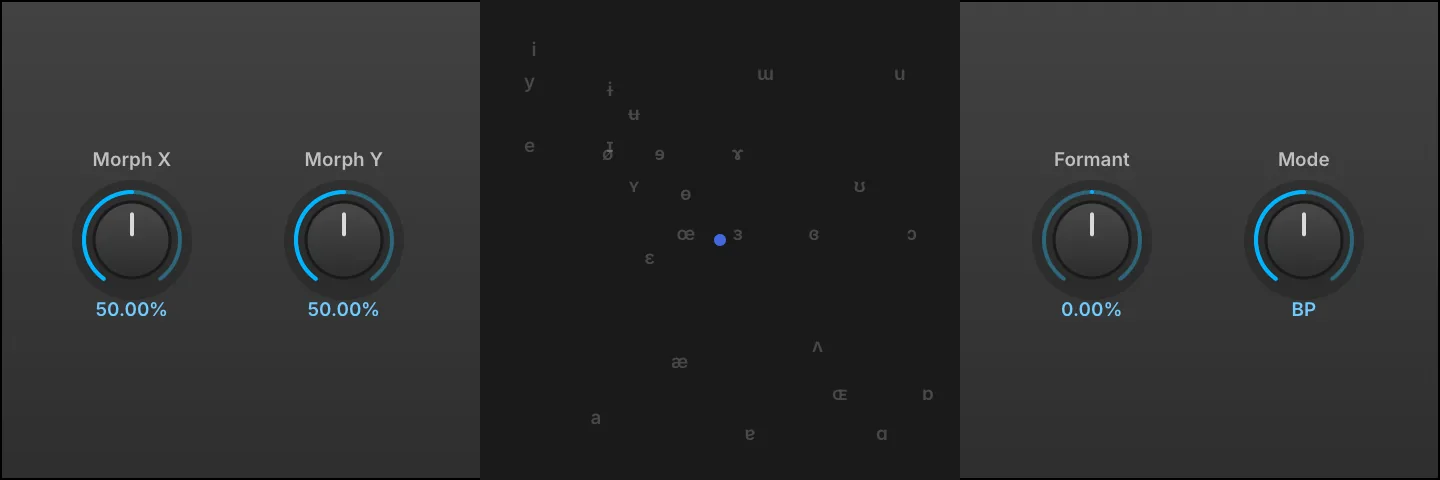
Infuse your sounds with a human touch. This formant filter uses precision resonant filters to mimic vowel shapes, allowing seamless blending between vowels for vocal-like textures and expressive effects.
Set with MORPH X (0–100 %) and MORPH Y (0–100 %) or click and drag the display to change the filter’s shape.
FORMANT (−100–100 %) controls how far the formant frequencies are shifted higher or lower.
MODE chooses the style of filter: low-pass (LP), band-pass (BP), or high-pass (HP).
Wahwah

Wahwah is a wah filter effect with full manual control over the wah amount, same as with an effect pedal.
WAH (0–100 %) sets the filter frequency, which is commonly modulated or controlled with a pedal or other MIDI controller.
DRIVE (0–100 %) sets the amount of overdrive applied.
MODEL chooses the pedal model, each with its own sweep range and resonance curve: Default, Cry, CryB, CryC, Vox, VoxM, or CryBassHigh.
MASTER (0–10) sets the output gain level.
Xpander Filter

A highly customizable multi-mode filter with 37 shapes, vintage and modern algorithms, built-in saturation and oversampling.
The number indicates the order of the filter (e.g. LP1 is a low-pass filter with a 6 dB/octave slope).
MODE sets the filter shape. Click the image to choose between 37 different options or use the left/right arrows to scroll through them.
Filter types include: LP - low-pass, HP - high-pass, BP - band-pass, AP - all pass, PK - peak filter, T - twin filter.
KEY TRACKING (0–100 %) changes how the cutoff frequency is adjusted relative to the note played. ALGORITHM allows you to choose between two modes: MODE I emulates a classic constant-Q filter solver, MODE II is a modern zero-delay filter solver. 2X enables oversampling for the filter and provides the cleanest results when active.
Overdrive
TYPE sets the style of overdrive used: Soft Saturation, Hard Clip, or Linear.
AMOUNT (−20–20 dB) sets the amount of overdrive used.
Filter
CUTOFF (20–20,000 Hz) sets the frequency for the filter; the note name of the corresponding frequency is also displayed (e.g. 2.00 kHz (B5)). RESONANCE (0–100 %) adjusts how much emphasis is given to the cutoff frequency. THICKNESS (0–100 %) overdrives the filter at lower frequencies to compensate for DC gain drop (e.g. crank it when you want more OOMPH than SIZZLE).
Equalizer
3 Band Shelf
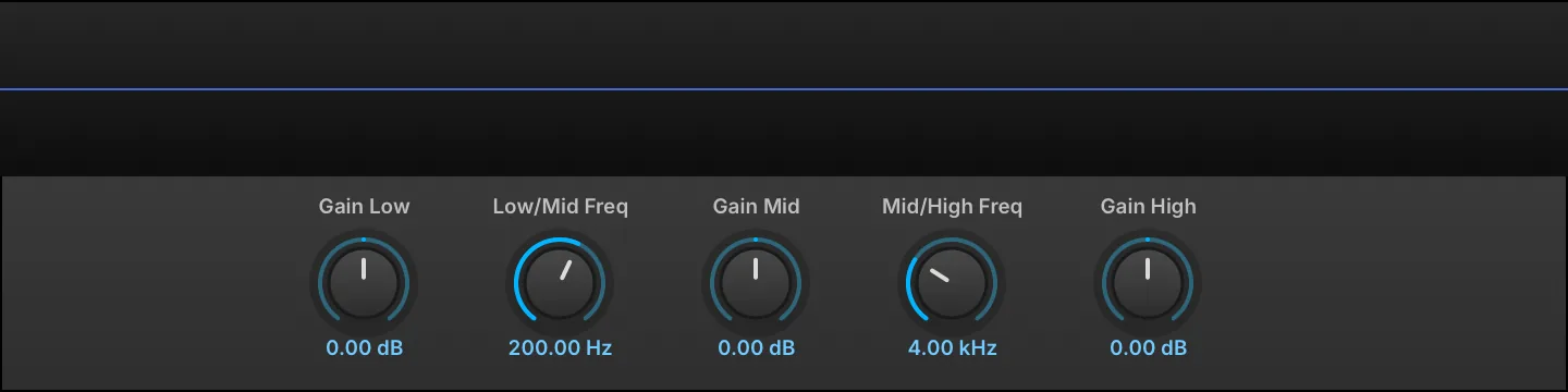
The 3 Band Shelf has Low, Mid, and High bands. The Mid band is a bell curve, while the Low and High bands are shelves.
The crossover points between the bands are set with the LOW/MID FREQ (20–1,000 Hz) and MID/HIGH FREQ (2,000–20,000 Hz) controls.
Each of the three bands has a GAIN (−24–24 dB) control for boosting or cutting its frequency.
Big Pi Tone

An emulation of the tone circuit in a popular fuzzbox guitar pedal.
At zero a low-pass filter is applied, at 10.00 a high-pass filter is applied, and the interim values are a blend of the two.
The blended result is similar to a shelving filter with a notch in the middle.
TONE (0–10) adjusts the amount and type of filter applied.
GAIN (0–10 dB) adjusts output level.
Convolver
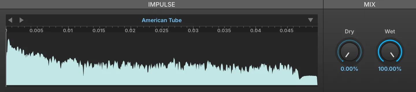
Convolver is a simple convolution processor, ideally suited for emulating EQs, cabinets, and so on. For reverb, the IReverb effect is recommended; see: Effects › Reverb › IReverb.
To load an IMPULSE RESPONSE, drag and drop an audio file to the sample area.
Mix
DRY (0–100 %) and WET (0–100 %) knobs set the balance between the dry (unaffected) and wet (affected) signal sent to the module’s output.
Impulse Files
To save the currently loaded impulse, use the Preset File menu and choose SAVE IMPULSE to save the current file or SAVE IMPULSE AS to save as a new file.
NORMALIZE POWER, enabled by default, scales each impulse response as it is loaded so that swapping impulses does not change the output level; it is reachable from the module’s parameter list rather than the front panel.
Digital EQ
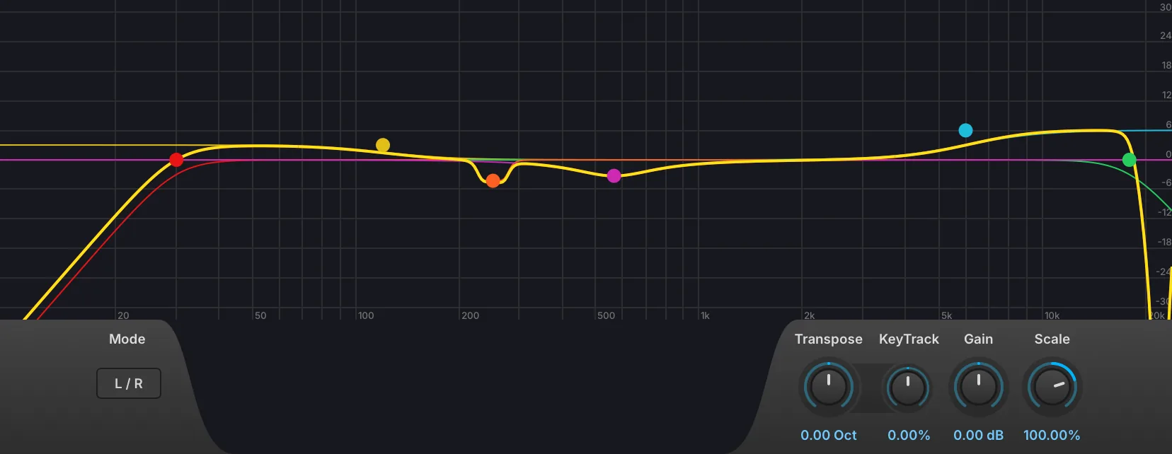
Digital EQ is a parametric EQ with up to 16 bands, variable filter shapes, L/R and M/S modes, interactive graphic display, transpose and key tracking.
The 16 bands each offer control of:
-
Bypass (power) button
-
Band selector
-
Channel selector: applies the band to both channels (All), or to the left or right channel only; in M/S mode, to the middle or side signal only.
-
EQ mode to choose the shape of the band: low-pass, high-pass, band-pass, notch, low-shelf, high-shelf and peak.
-
Slope sets the filter slope of the band: 6, 12, 18, 24, 36, 48, 72 or 96 dB/oct.
-
Frequency sets the frequency of the band.
-
Q adjusts the filter resonance.
-
Gain adjusts the band level in dB.
-
Bandwidth changes the frequency width.
-
Split (scissors) button copies the band into the next unused band and assigns one copy to the left channel and the other to the right.
-
Remove (X) button disables the band and takes it off the display.
In addition to the knobs and toggle switches, the bands can also be edited graphically in the frequency graph:
-
Press and drag a point to adjust its frequency by dragging right/left, or its gain by dragging up/down.
-
Press and drag a band’s color bars to adjust Q.
-
Right-click a point to enable/disable the band.
-
Double-click a point to return it to its default value.
-
When a band is selected, an information box is displayed in the upper left. As the band is adjusted, its Gain, Frequency, and Q values update in real time.
To view a larger graph, drag the bottom edge of the module to resize it.
MODE sets the stereo mode to L/R or M/S.
GAIN (−30–30 dB) adjusts overall output level.
-
SCALE (−200–200 %) scales the gain of every band and the overall Gain; negative values invert the boosts and cuts.
-
TRANSPOSE (−10 to 10 octaves) shifts the frequency of every band.
KEY TRACKING (−100–100 %) changes how the cutoff frequency is adjusted relative to the note played.
Harmonic Resonators
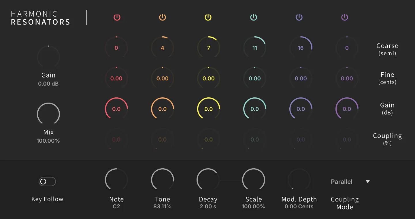
The effect version of our resonator bank, offering 6 channels with coarse and fine tune, gain, coupling, key follow, and more.
The 6 bands each offer control of:
-
Bypass (power) button
-
Coarse to set the filter frequency in semitones.
-
Fine to fine-tune the filter frequency in cents.
-
Gain adjusts the band level in dB.
-
Coupling (0–100 %) to set the coupling amount; only active in Reflect and RotCirc (aka Circular Rotation) modes.
GAIN (−20–20 dB) adjusts overall output level. MIX (0–100 %) sets the dry and wet signal balance.
KEY FOLLOW to enable key tracking mode, NOTE sets the base note for the filters when the Key Follow switch is off.
TONE (0–100 %) adjusts the high frequency damping of each harmonic resonator, sweeping the damping corner from 440 Hz at 0 % (darkest, most damped) up to 20 kHz at 100 % (brightest, undamped).
DECAY (20–20,000 ms) sets the filter decays of all bands. SCALE (0–100 %) evens out the band decays: at 0 % a band tuned an octave up rings half as long as one at the played note, at 100 % every band rings for the full Decay time whatever its tuning. MOD. DEPTH (0–20 cents) sets the filter modulation depth in cents.
COUPLING MODE sets the relationship between the filter bands:
-
Parallel mode: processing all bands in parallel (or independently).
-
Reflect mode: a weighted sum of each resonator’s energy is fed back into all the others.
-
RotCirc mode: rotates a small fraction of energy from each band to the next (circularly).
Passive EQ
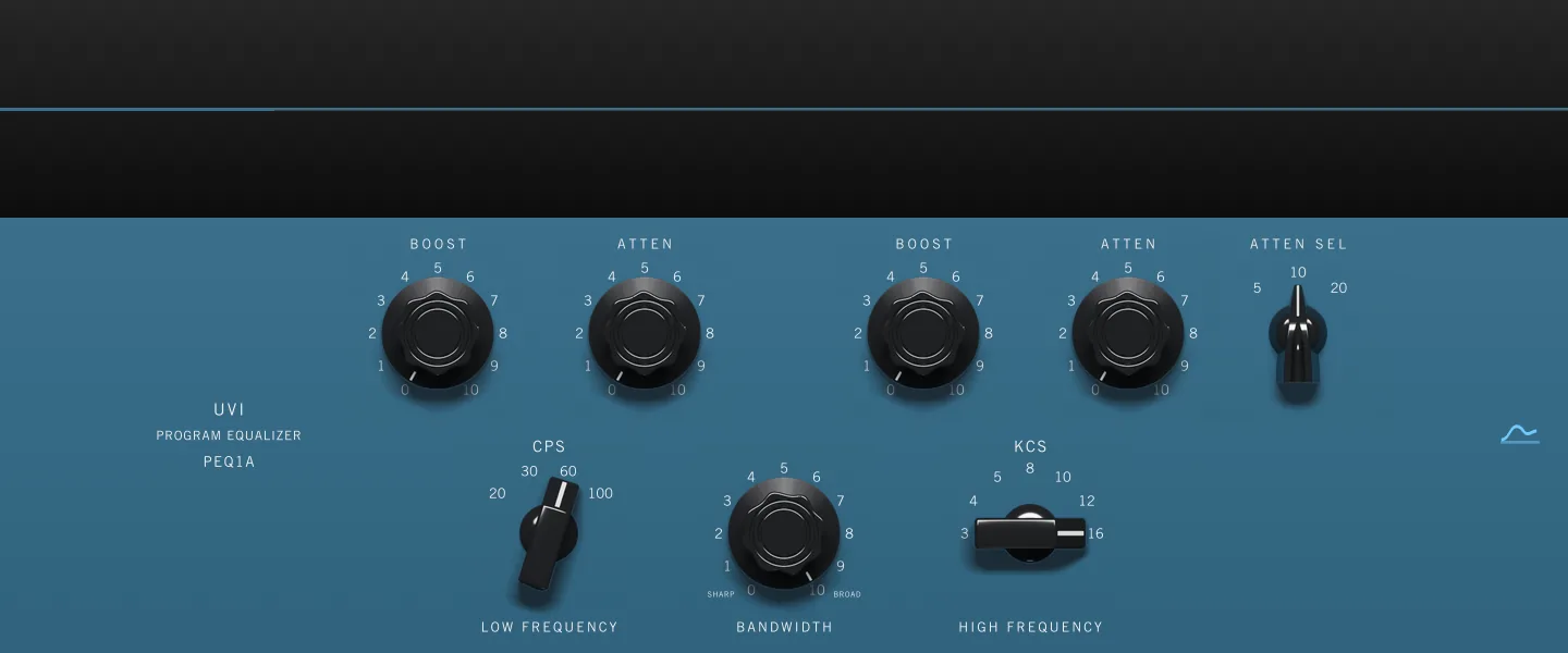
Passive EQ is a model of a passive tube program equalizer, solved from the state space of the original circuit rather than assembled from a chain of digital filters. Its low band boost and attenuation run through separate networks and land on deliberately offset curves, so raising and cutting the same frequency at once does not cancel out. The front panel carries no module name, only the PROGRAM EQUALIZER legend of the hardware it follows.
LOW BOOST (0–100 %) and LOW ATTENUATION (0–100 %) set the amount of boost and of cut applied at the low frequency. The cut is centered above the boost, so applying both leaves a lifted bottom with a broad dip just above it — the trick this design is known for, which thickens a sound while keeping it clear.
LOW FREQUENCY (20, 30, 60, 100 Hz) selects the frequency the low boost and the low attenuation act on; the panel marks it in CPS.
HIGH BOOST (0–100 %) sets the amount of boost applied at the high frequency, and BANDWIDTH (0–100 %) sets the width of that peak, sharp at 0 % and broad at 100 %.
HIGH FREQUENCY (3, 4, 5, 8, 10, 12, 16 kHz) selects the frequency of the high boost peak; the panel marks it in KCS.
HIGH ATTENUATION (0–100 %) sets the amount of cut applied by the high shelf, and HIGH ATTEN. SEL. (5, 10, 20 kHz) selects the frequency it acts on. The boost and the shelf are independent, so a peak can be lifted underneath a top end that is being pulled down.
The CURVE button in the upper right of the panel shows or hides the response display above it, which plots the resulting magnitude from 20 Hz to 20 kHz on a ±20 dB scale.
Tilt

With negative values, the low shelf is boosted and the high shelf is cut; the opposite occurs with positive values.
The Tilt module has two shelf bands, a low shelf and a high shelf, which are applied inversely.
The TILT (−6–6 dB) control sets the amount of gain applied to each band.
CUTOFF (20–20,000 Hz) sets the frequency for the EQ; the note name corresponding to the frequency is also displayed, for example, 2.00 KHZ (B5).
Tone Stack

Tone Stack emulates the tone controls found on many common amplifier heads.
MODEL chooses the style of amplifier head.
BASS (0–100 %), MID (0–100 %), and TREBLE (0–100 %) controls set the relative levels for each tone band.
GAIN (0–100 %) sets an output boost applied after the tone stack, rising from unity at 0 % to +20 dB at 100 %; it only ever adds level, it never attenuates.
Amp & Stereo
Autopan

Autopan varies stereo panning with an LFO.
SPEED (0–20 Hz) sets how quickly one auto-pan cycle is completed, in Hz or bars/beats (if tempo-synced).
DEPTH (0–100 %) sets how far across the stereo field the auto-pan will cover, with 100 percent covering the full distance from hard left to hard right.
MODE chooses the pan law used by the auto-pan cycle: Linear, Equal-power, Balance, or Rotate.
Gain

Gain is a simple level adjustment module, used to boost or cut the signal level.
VOLUME sets the amount of boost or cut, from +12 dB to -∞
Gain Matrix
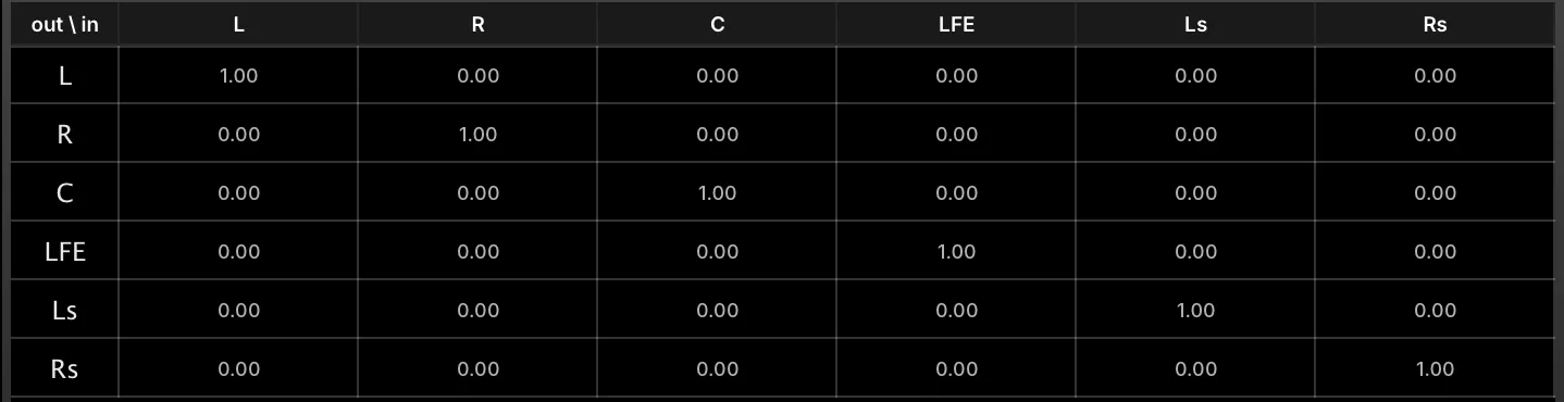
Gain Matrix sets the gain level and phase of each channel. This allows for simple per-channel gain adjustments, or for specialized gain/phase transformations. Factory presets provide some common transformations, such as decoding mid-side to stereo.
The INPUT channels are listed down the side, and the OUTPUT channels are listed across the top. Each in/out relationship can be edited by typing in a new value or clicking and dragging the value:
-
At 1.00, the signal is passed through at full strength and its original phase.
-
At 0.00, output is silenced for that channel.
-
At -1.00, the output is passed through at full strength but with the opposite phase.
Gain Matrix also supports multi-channel configurations, such as quad, 5.1, 7.1, and others.
Tremolo

Tremolo varies amplitude with an LFO.
FREQ (0–20 Hz) sets how quickly the LFO cycle is completed, in Hz or bars/beats (if tempo-synced).
DEPTH (0–100 %) sets how far across the gain range the cycle will cover, with 100 percent covering the full distance from -∞ to 0 dBFS.
UVI Wide

UVI Wide is a stereo width enhancer with a high-shelf filter.
WIDTH (−100–100 %) adjusts the stereo spread of the module’s output. At zero, the stereo image of the input signal is unaffected. Positive values increase the stereo spread and negative values reduce it, down to a mono signal at -100%.
DELAY (−15–15 ms) sets the amount of delay applied to one channel to help create a wider stereo image.
Extra Width
The Extra Width controls provide additional frequency control by way of a high-shelf EQ applied to the side channel of the module’s M/S decomposition, so it emphasizes (or tames) the stereo difference signal only.
EXTRA WIDTH FREQ (2,000–20,000 Hz) sets the EQ frequency.
EXTRA WIDTH GAIN (−15–15 dB) sets the EQ gain adjustment (+/-).
Drive & Distortion
Analog Crunch

Analog Crunch is inspired by overdrive/distortion effect pedals commonly used with electric guitars.
INPUT GAIN (−30–20 dB) sets the gain adjustment into the module, before any distortion is applied.
OVERDRIVE (0–10) and TRASH (0–100 %) set the amount and character of the distortion.
The SHAPING DISPLAY plots the module’s output waveform (blue) against a reference sine wave input (purple), so the effect of the current settings can be seen directly.
Oversampling
Sets the AMOUNT of oversampling applied (if any), from 2x to 16x.
Output
MIX (0–100 %) sets the balance between the clean and overdriven signals. GAIN (−40–10 dB) sets the final, post-distortion gain adjustment.
Diode Clipper

Diode Clipper is a circuit-modeled diode clipping stage similar to those found in many overdrive stomp boxes.
The circuit of Diode Clipper includes a passive nonlinear, dynamic-driven HP/LP filter that exhibits effects like hysteresis when saturated.
DRIVE (0–30 dB) controls the overall effect intensity.
ASYMMETRY (0–100 %) shifts the saturation symmetry between the two diodes, affecting the even/odd harmonic ratio.
The SHAPING DISPLAY plots the module’s output waveform (blue) against a reference sine wave input (purple), so the effect of the current settings can be seen directly.
Contour
TONE (100–20,000 Hz) sets the frequency of the LP filter. HIGH PASS (1–20,000 Hz) controls the HP filter frequency.
Output
GAIN (−40–10 dB) sets the final, post-distortion gain adjustment.
Drive

Drive offers a straight-ahead drive/distortion, with three different flavors of distortion.
As oversampling is processor intensive, it’s recommended to apply oversampling as little as is necessary to reduce unwanted aliasing. Often, no oversampling will be needed.
MODE sets the style of drive (Analog, Mild, or Strong).
AMOUNT (0–100 %) sets the amount of drive.
Use OVERSAMPLING to set the amount of oversampling applied (if any), from 2x to 16x.
Exciter

Exciter is a classic exciter effect, adding brightness and saturation.
INPUT GAIN (−30–20 dB) sets the gain adjustment into the module, before any distortion is applied.
AMOUNT (0–15) chooses the amount of excitation applied.
The SHAPING DISPLAY plots the module’s output waveform (blue) against a reference sine wave input (purple), so the effect of the current settings can be seen directly.
Mode
MODE sets the style of exciter, using common characteristics of Tape or Tube exciters.
Use OVERSAMPLING to set the amount of oversampling applied (if any), from 2x to 16x.
Output
MIX (0–100 %) sets how much of the excited signal is blended into the output. In Tape mode this is a crossfade against the clean signal; in Tube mode the clean signal is never attenuated, so the excitation is added on top of it.
GAIN (−40–10 dB) sets the final, post-distortion gain adjustment.
Fuzz

Fuzz is inspired by classic fuzz guitar and bass effect pedals.
INPUT GAIN (−30–20 dB) sets the gain adjustment into the module, before any fuzz is applied.
OVERDRIVE (0–10) and TRASH (0–100 %) set the amount and character of the fuzz.
The SHAPING DISPLAY plots the module’s output waveform (blue) against a reference sine wave input (purple), so the effect of the current settings can be seen directly.
Oversampling
Sets the AMOUNT of oversampling applied (if any), from 2x to 16x.
Output
MIX (0–100 %) sets the balance between the clean and fuzzed signals.
GAIN (−40–10 dB) sets the final, post-distortion gain adjustment.
Guitar Boxes

Guitar Boxes emulates a guitar cabinet, with multiple cabinet models and mic types.
MIX (0–100 %) sets the balance between the original and amplified signals.
SEPARATION (−30–30 ms) offsets one channel against the other to emulate the distance from cabinet to microphone: positive values delay the left channel, negative values the right. It has no effect on a mono signal.
SPREAD sets the amount of stereo spread, from zero percent (mono) to 100 percent (full stereo).
CABINET chooses the cabinet, from well-known models to general device types to unusual FX simulations. It is picked from the icon at the left of the panel, and the display beside it draws the frequency response of the cabinet and microphone together, from 20 Hz to 20 kHz.
MICROPHONE adjusts the characteristic of the microphone capturing the amplified signal, as a Dynamic, Condenser, or Ribbon mic. It has its own icon beside the cabinet.
Magnetic Bass Shaper

Abuse the saturating hysteretic behavior of famous inductors to shape and add punch to bass sounds while leaving high frequencies clean.
GAIN (−30–30 dB) sets the gain adjustment into the module.
DRIVE (0–30 dB) sets the amount of the drive applied to the signal.
MODEL selects the magnetization model of the coil, Model C or Model I, each with its own hysteresis behavior. INDUCTOR selects the coil itself, Fasel Red or Fasel Yellow, each measured to give a unique distortion profile.
CUTOFF (1–500 Hz) sets the frequency cutoff of the inductor circuit.
GAIN (−30–30 dB) sets the output gain adjustment.
The SHAPING DISPLAY plots the module’s output waveform (blue) against a reference sine wave input (purple), so the effect of the current settings can be seen directly.
Overdrive

Overdrive emulates overdrive distortion commonly used on guitars.
INPUT GAIN (−30–20 dB) sets the gain adjustment into the module, before any distortion is applied.
OVERDRIVE (0–10) sets the gain driving the overdrive stage, and TRASH (0–100 %) brings in the soft saturation that gives it its character. With TRASH at zero the drive path stays clean, however high OVERDRIVE is set.
The SHAPING DISPLAY plots the module’s output waveform (blue) against a reference sine wave input (purple), so the effect of the current settings can be seen directly.
Oversampling
Sets the AMOUNT of oversampling applied (if any), from 2x to 16x.
Output
MIX (0–100 %) sets the balance between the clean and overdriven signals.
GAIN (−40–10 dB) sets the final, post-distortion gain adjustment.
TS Overdrive

Drive-stage emulation of the Tube Screamer overdrive pedal with custom mods.
INPUT VOLTAGE (0.1–2) sets the input voltage adjustment into the module, before any distortion is applied.
DRIVE (0–100 %) and ASYMMETRY (0–100 %) set the amount and character of the overdrive.
The SHAPING DISPLAY plots the module’s output waveform (blue) against a reference sine wave input (purple), so the effect of the current settings can be seen directly.
Bandwidth
LOW FREQ (100–2,000 Hz) and HIGH FREQ (10,000–100,000 Hz) set the corners of the band the drive stage boosts and clips. High Freq is the corner at minimum Drive; raising Drive lowers it by up to a factor of ten (1,000–10,000 Hz at full Drive), which is why its range extends past the audible band.
OUTPUT GAIN (0.1–10) sets the final, post-distortion gain.
Tube Amp
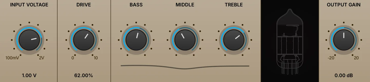
An exacting digital model of a British high-gain classic. By simulating the full circuit and vacuum tubes, Tube Amp delivers the authentic tone, grit, and dynamic response of legendary hardware.
INPUT VOLTAGE (0.1–2) sets the input voltage adjustment into the module, before any distortion is applied.
DRIVE (0–100 %) sets the amount of the overdrive.
BASS (0–100 %), MIDDLE (0–100 %) and TREBLE (0–100 %) adjust the low, mid and high frequencies of the amplification signal.
OUTPUT GAIN (0.1–10) sets the final, post-distortion gain.
Wavefolder
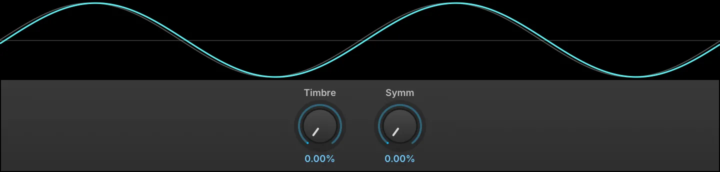
Wavefolder is the folding circuit of the West Folder oscillator on its own, as an effect: instead of clipping a signal that is driven too hard, it folds the peaks back on themselves, adding harmonics that move with the input level rather than simply squaring it off. It works on anything, but is at its most characteristic on sustained tones and simple waveforms, where each new fold is audible as it appears.
The display draws a sine run through the folder at the current settings, over the same sine undistorted. It is normalized to its own peak, so what the controls change is the shape rather than the level.
TIMBRE (0–100 %) sets the gain into the folding circuit, from half the level of the input up to ten times it. The harder it drives, the more times the wave folds back on itself, so it is the main control over how much harmonic content is added.
SYMM (0–100 %) offsets the signal before it reaches the folder, so it no longer folds symmetrically about zero. This brings in even harmonics, for a hollower, reedier tone.
Wave Shaper
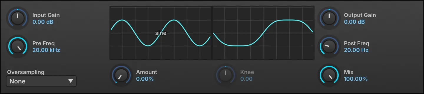
Wave Shaper distorts the input signal by transforming the shape of the waveform, which often results in heavily distorted sounds.
INPUT GAIN (−40–40 dB) sets the gain adjustment into the module, and PRE FREQ (20–22,000 Hz) sets the frequency of a low-pass filter applied before any waveshaping.
Choose the WAVE SHAPE by clicking the waveform and selecting a wave from the menu, then use AMOUNT (0–100 %) and KNEE (−10 to 10) to adjust characteristics of the wave shape. (Not available in some shapes).
AMOUNT is active for the sine, Fold-back, tanh, atan, HyperSine, Asym and Exp shapes, and KNEE for tanh, atan, Damped sat and Exp. Both controls are grayed out for the shapes that do not use them.
Use OVERSAMPLING to set the amount of oversampling applied (if any), from 2x to 16x. As oversampling is processor intensive, it’s recommended to apply oversampling as little as is necessary to reduce unwanted aliasing. Often, no oversampling will be needed.
POST FREQ (2–20,000 Hz) sets the frequency of a high-pass filter applied after waveshaping. OUTPUT GAIN (−40–40 dB) sets the gain adjustment, after waveshaping is applied.
MIX (0–100 %) sets the balance between the dry and shaped signals.
Dynamics
3-Band Compressor
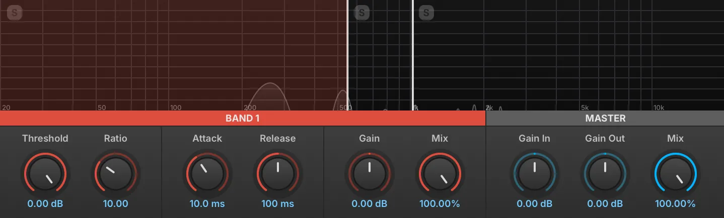
The 3-Band Compressor is a multiband version of the compressor, with adjustable crossover frequencies.
The 3-Band Compressor has Low, Mid, and High bands.
To select a band to edit, click in the corresponding area of the display - the parameters for that band will be displayed below in a matching color.
To change the crossover frequency between bands, click-drag the border line between them.
To solo a band, click the [S] button in the upper-left of the band display.
Band 1–3 Each of the three bands has standard compressor controls: THRESHOLD (−130–0 dB), RATIO (1–30), ATTACK (0–500 ms), RELEASE (0–5,000 ms), GAIN (−30–30 dB) and MIX (0–100 %). For more information on compressor settings, see: Effects › Dynamics › Compressor Expander.
Each band also carries an AUTO-MAKEUP parameter, which adds an automatic compensation for that band’s gain reduction on top of its Gain setting. It is off by default and has no switch on the panel; reach it from the parameter list or as a modulation target.
Master GAIN IN (−30–30 dB) sets the global input gain. GAIN OUT (−30–30 dB) sets the global output gain. MIX (0–100 %) sets the dry and wet signal balance.
3 Band Limiter
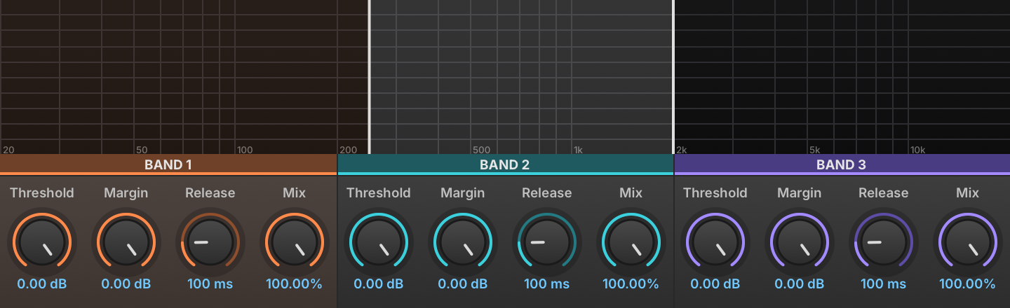
The 3 Band Limiter is a multiband version of the Studio Limiter, with adjustable crossover frequencies.
The 3 Band Limiter has Low, Mid, and High bands. The crossover points between the bands are set with the LOW/MID FREQ (20–20,000 Hz) and MID/HIGH FREQ (20–20,000 Hz) controls.
Each of the three bands has standard limiter controls: THRESHOLD (−20–0 dB), MARGIN (−5–0 dB), and RELEASE (10–500 ms). For more information on limiter settings, see: Effects › Dynamics › Studio Limiter.
Compressor Expander
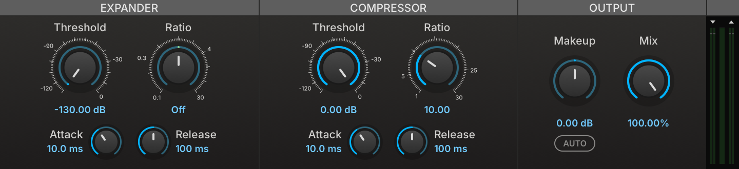
Compressor Expander is a dual dynamics processor — the compressor tames signal peaks over a chosen threshold, and the expander attenuates the signal below a second, independent threshold.
Both the compressor and expander have Threshold, Ratio, Attack, and Release controls. THRESHOLD (−130–0 dB) sets the level at which the compressor or expander will be applied. RATIO sets the ratio between input gain and output gain. The expander RATIO (0.1–30) expands downward above 1, lifts low levels below 1, and does nothing at 1. ATTACK (0–500 ms) and RELEASE (0–5,000 ms) set the speed at which the compressor or expander begins or stops processing the signal after it has crossed the threshold.
MAKEUP GAIN (−30–30 dB) applies a manual gain adjustment to compensate for the gain reduction of the compressor. AUTO MAKEUP adds a further compensation derived from the compressor’s threshold and ratio; it is applied on top of Makeup Gain, not in place of it.
MIX (0–100 %) sets the balance between the dry (unaffected) and wet (affected) signal sent to the module’s output.
Lastly, the INPUT METER on the left side of the module displays the level of the input signal, and the GAIN REDUCTION METER on the right side of the module displays the amount of gain reduction applied. Note that the righthand meter is not an output meter.
FET Compressor

FET Compressor is a model of the classic FET limiting amplifier, solved from its circuit so that the ratio, the sidechain gain and the output line amp all interact as they do in the hardware. It has no threshold control: the ratio buttons are what set the shape of the curve, and Input Gain is what moves the knee along it, as on the original. Its attack and release are numbered dials rather than times.
IN (−20–20 dB) sets the gain applied to both the signal and the detector, so it moves the operating point on the curve as well as the level. OUT (−40–40 dB) is the makeup gain applied at the output.
RATIO is a column of buttons reading 4:1, 8:1, 12:1 and 20:1, the machine’s own markings rather than measured slopes. Each one sets the sidechain gain and the transistor’s bias together, which is what the hardware’s ratio switch does.
ALL presses all four at once, as the original lets you jam them: the ladder’s sections short together and the sidechain gain rises without the bias following, so it reduces more gain than any of the four buttons, even 4:1, and lands off the path the four buttons travel. Ratio goes inert while it is engaged.
CONT replaces the column of buttons with a continuous control over the same 4:1 to 20:1 range, for settings between the machine’s four.
ATTACK (1–7) and RELEASE (1–7) are the panel’s numbered dials, 1 the slowest setting and 7 the fastest, each step being the same ratio of time rather than the same number of milliseconds. The circuit’s slow reservoir keeps the release program dependent, so it runs longer after a long passage of compression, which is why the dial is marked rather than timed.
DRIVE (−6–40 dB) drives the output line amp. It is level-compensated afterwards, so it changes the tone of the output stage rather than its loudness.
MIX (0–100 %) sets the balance between the dry (unaffected) and wet (affected) signal sent to the module’s output.
The VU METER reads either gain reduction or output level, selected by the GR and OUT buttons below it.
The ANALYSIS button unfolds three displays below the panel. The static curve plots output against input for a held sine, the diagonal being unity and the grid 10 dB; Ratio, All and In all move it. The drive display shows a full-scale sine through the output line amp at the current Drive setting, against the same sine undistorted. The third scrolls the input and output levels over time.
Feedback Compressor
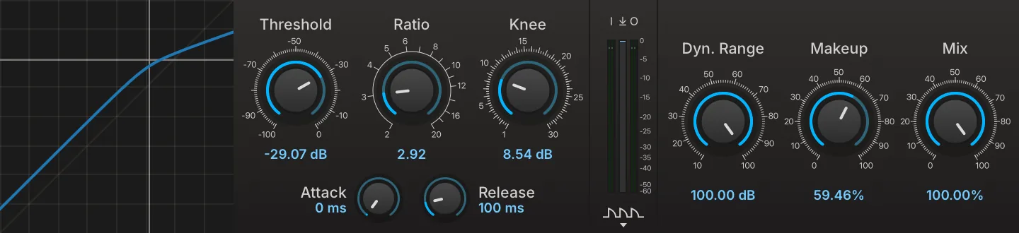
Feedback Compressor is a modern take on vintage compression. By focusing solely on feedback designs we wanted to retain the particular behavior and characteristics of old compressors, such as time constants that depend on the ratio and signal, and a limited amount of gain reduction, but at the same time offer full parametric control over the transfer function, soft-knee, makeup gain, and parallel compression.
THRESHOLD (−100–0 dB) sets the output level above which the compressor starts reducing gain. RATIO (2–20) sets the ratio between input gain and output gain. KNEE (1–30 dB) adjusts the smoothness of the compression knee. ATTACK (0–100 ms) and RELEASE (50–1,000 ms) set the speed at which the compressor begins or stops processing the signal after it has crossed the threshold; the attack time also scales with the ratio, so a given attack setting engages more gradually at higher ratios.
The I↓O METER displays the level of the input, gain reduction and output signal, and the switch at the bottom of the meters toggles the TIMELINE to display the gain reduction over time.
INPUT GAIN (−40–40 dB) sets the gain applied to the signal before compression, and OUTPUT GAIN (−40–40 dB) sets the gain applied at the very output, after compression and mix.
DYN. RANGE (10–100 dB) caps the maximum gain reduction the compressor can apply, however far the signal runs above the threshold.
MAKEUP GAIN (0–100 %) sets how much of the automatic gain compensation is applied, from none at 0 % to full compensation at 100 %. The amount compensated is computed from the threshold, ratio and dynamic range, so it follows the compression settings rather than being dialed in decibels.
MIX (0–100 %) sets the balance between the dry (unaffected) and wet (affected) signal sent to the module’s output.
Feedforward Compressor
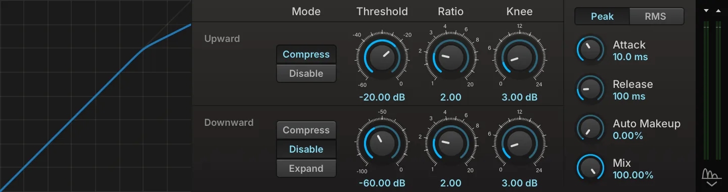
Feedforward Compressor derives its gain from the incoming signal, measured before any processing, so its response depends only on what enters the effect and not on what it has already done to it. Its transfer curve is built from two independent segments, one acting above an upward threshold and one below a downward threshold, each with its own ratio and knee, so a single instance can flatten peaks, lift a quiet body, or push a tail further down. A shared envelope, peak or RMS detection, continuous auto makeup and a dry/wet mix are common to both.
The STATIC CURVE on the left plots output against input for the current settings, with a marker following the incoming level.
UPWARD acts on everything above its threshold, and is switched between DISABLE and COMPRESS. Its THRESHOLD (−60–0 dB) sets the detected level at which the segment starts acting, RATIO (1–20) sets the input-to-output ratio above it, and KNEE (0–24 dB) sets the width of the transition around it, 0 dB giving a hard corner.
DOWNWARD acts on everything below its threshold, and is switched between DISABLE, COMPRESS, which lifts quiet levels, and EXPAND, which pushes them further down. Its THRESHOLD (−100–0 dB), RATIO (1–20) and KNEE (0–24 dB) work as they do on the upward segment, applied in the direction the mode selects.
The GLOBAL section applies to both segments. ATTACK (0–500 ms) and RELEASE (0–5,000 ms) set the time the detector takes to follow a rise and a fall of the input level. PEAK / RMS selects whether that level is measured as a peak or as an RMS average, peak reacting to transients and RMS to the body of the signal.
AUTO MAKEUP (0–100 %) sets how much automatic gain compensation is applied, from none at 0 % to bringing the loudest output back to 0 dB at 100 %.
MIX (0–100 %) sets the balance between the dry (unaffected) and wet (affected) signal sent to the module’s output.
The two meters in the well at the right edge of the panel show the input and output levels, marked with a downward and an upward arrow for the two buses, and the button below them unfolds a scrolling history of both under the panel.
Gate

Gate is a traditional gate, silencing signals below a chosen threshold.
THRESHOLD (0–1) sets the level at which the gate will be applied.
ATTACK (0.0001–0.1 s) and RELEASE (0.01–1 s) set the speed at which the gate begins or stops processing the signal after it has crossed the threshold.
Maximizer
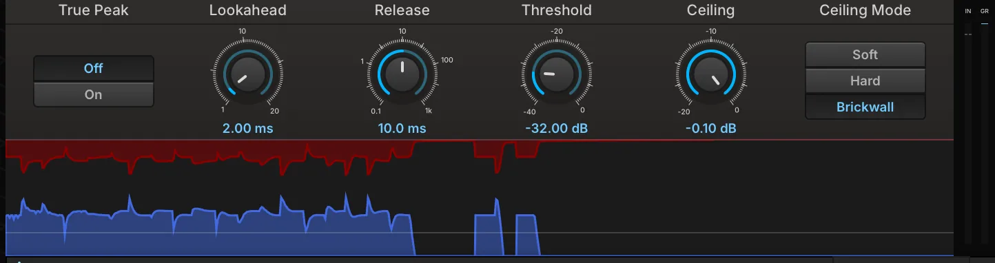
Maximizer is a lookahead limiter with a graphical timeline to visualize the dynamic range of the input and output.
THRESHOLD (−40–0 dB) sets the level at which limiting will be applied, and CEILING (−20–0 dB) sets the maximum output level.
LOOKAHEAD (1–20 ms) sets the amount of time the module will look ahead at the input signal; longer lookahead times can achieve a better response for transients and other sudden changes in amplitude.
RELEASE (0.1–1,000 ms) sets the speed at which the limiter stops processing the signal after it has fallen below the threshold.
CEILING MODE is a column of buttons setting how the ceiling is held. Soft lets the Attack setting shape the envelope, so the ceiling is approached rather than guaranteed; Hard keeps that envelope and puts a clipper at the ceiling behind it; and Brickwall, the default, uses an instant attack so the envelope enforces the ceiling on its own.
ATTACK (0–20 ms, default 0 ms) is not on the panel; reach it from the parameter list. It sets the time the gain reduction takes to engage and is used by Soft and Hard only.
TRUE PEAK switches between Off, where the ceiling holds for sample peaks, and On, where it also holds for the inter-sample peaks found on a four-times oversampled sidechain.
The TIMELINE displays the input signal and gain reduction over time. The blue graph rises from the bottom of the timeline and indicates the amplitude of the input signal; the red graph grows downward from the top of the timeline and indicates gain reduction.
The INPUT METER on the left side of the module displays the level of the input signal, and the GAIN REDUCTION METER on the right side of the module displays the amount of gain reduction applied. Note that the right-hand meter is not an output meter.
Opal
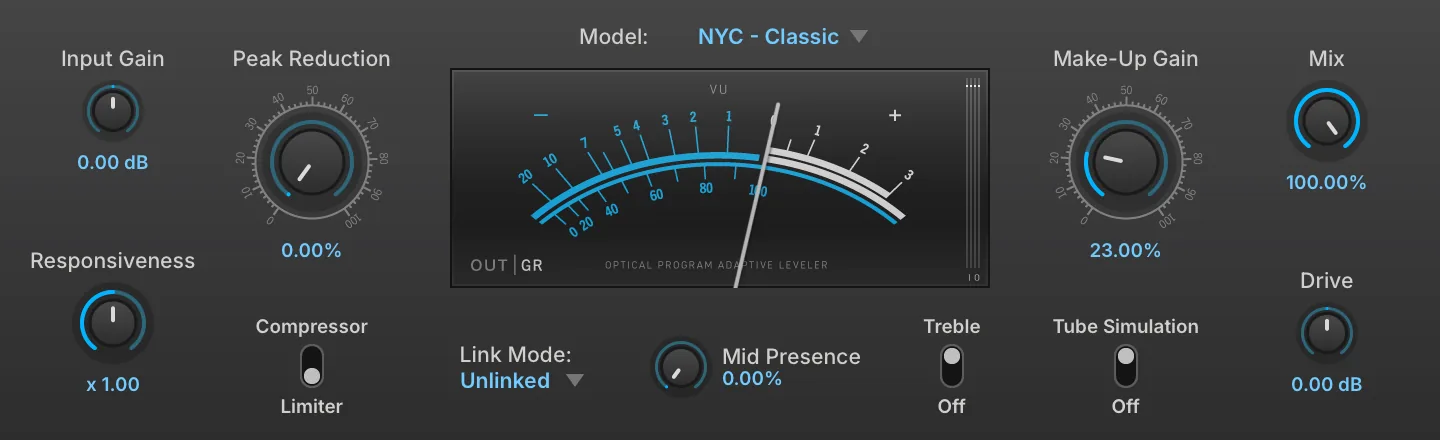
Based on a classic hardware optical compressor, Opal provides impressive realism thanks to deep physical modeling. 7 uniquely modeled flavors are available offering a range of useful characters.
MODEL chooses a model among seven emulations of real studio leveling amplifiers (optical compressors), each with its own character (dynamic range and response time).
INPUT GAIN (−20–20 dB) controls the gain applied to the signal before compression.
PEAK REDUCTION controls the detection threshold. Maximal threshold at 0% peak reduction, minimal threshold at 100 % peak reduction.
RESPONSIVENESS (0.1–10) multiplies the response time (attack and release, jointly). The response time is still program-dependent but can be set shorter or longer for a given input.
COMPRESSOR/LIMITER switches the operation mode between compressor and limiter.
LINK MODE click to show the drop-down menu to set the stereo link mode based on Left, Right, Mono (LR sum), Max ch (the louder of the Left or Right channels) or Unlinked (link off).
MID PRESENCE (0–100 %) controls the sidechain filter frequency response, this corresponds to the original R37 “emphasis” control.
TREBLE enables the treble boost of the Make-Up Gain stage. It acts on the non-tube path only, so the control is unavailable while TUBE SIMULATION is active.
VU METER indicates output or gain reduction level by OUT|GR toggle, the IO METER displays the level of the input and output signal.
MAKE-UP GAIN (0–100 %) applies a manual gain adjustment to compensate for the gain reduction of the compressor.
TUBE SIMULATION turns on or off the full physical modeling tube simulation for Make Up Gain. More CPU intensive when switched on.
MIX (0–100 %) sets the balance between the dry (unaffected) and wet (affected) signal sent to the module’s output.
DRIVE (−40–40 dB) adjusts the gain applied to the signal fed into Make Up Gain when the Tube Simulation is active.
EXTERNAL drives the detection from the external sidechain input instead of the signal being processed.
Studio Limiter

The Studio Limiter is a high-quality limiter, suited for individual parts or for full stereo mixes.
THRESHOLD (−20–0 dB) sets the level at which limiting will be applied.
MARGIN (−5–0 dB) sets the maximum output level, which can also be thought of as the margin between the maximum signal output by the limiter and zero dBFS.
RELEASE (10–500 ms) sets the speed at which the limiter stops processing the signal after it has fallen below the threshold.
MIX (0–100 %) sets the balance between the dry (unaffected) and wet (affected) signal sent to the module’s output.
Pitch
Harmonizer
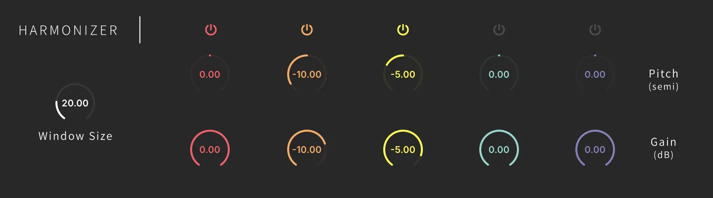
Harmonizer is a simple and effective effect to create up to 5-voice harmony. Ideal for sounds that have a dominant monophonic component but are not required to be exactly periodic.
WINDOW SIZE (10–60 ms) sets the size of the window (a processing unit applied to the signal for pitch-shifting).
POWER enables the voice.
PITCH sets the pitch shift in semitones (+/-12).
GAIN (−40–0 dB) adjusts the voice gain.
Shifter

Shifter is a simple and effective effect using the pitch-shifting engine, ideal for sounds that have a dominant monophonic component but are not required to be exactly periodic.
PITCH sets the pitch shift in semitones (+/-12), and FINE adjusts the pitch shift in cents (+/-100). Enable QUANTIZE to make a stepped pitch bend effect when controlling or modulating the pitch control in real time.
WINDOW SIZE (10–60 ms) sets the size of the window (a processing unit applied to the signal for pitch-shifting).
MIX (0–100 %) sets the balance between the dry (unaffected) and wet (affected) signal sent to the module’s output.
Analysis
Loudness Meter
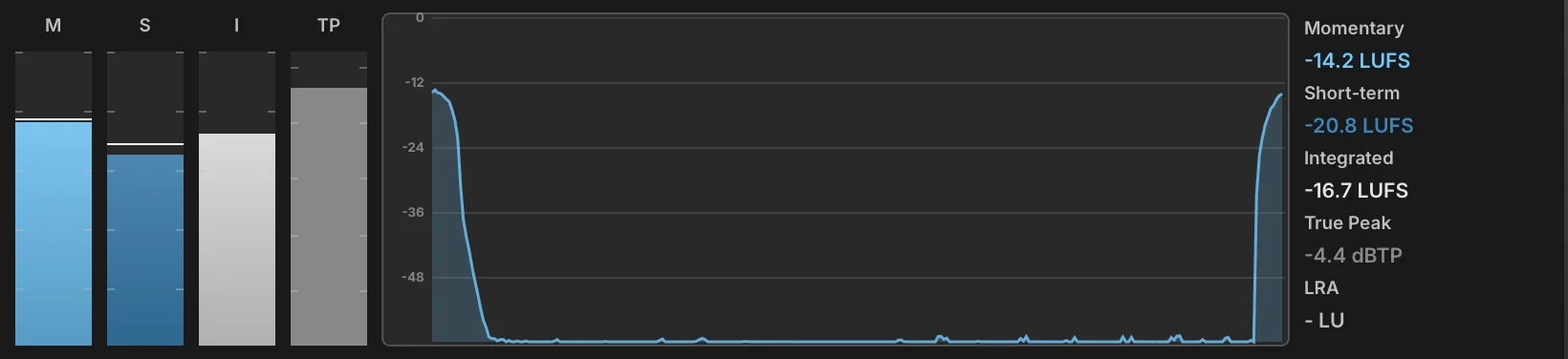
The Loudness Meter measures program loudness to the ITU-R BS.1770 and EBU R128 broadcast standards, showing momentary, short-term and integrated loudness alongside true peak and loudness range. It is the meter to reach for when a patch has to sit at a delivery target rather than simply avoid clipping, since none of those readings can be inferred from a peak meter. The module has no settings: everything on it is a reading.
Four bars fill the left of the display, labeled above their scales. M is the momentary loudness, measured over a 400 ms window, and S the short-term loudness, measured over 3 s; both carry a horizontal line marking the highest value reached since the last reset. I is the integrated loudness, gated as the standard prescribes and accumulated over the whole measurement. TP is the true peak, measured with four-times oversampling so that peaks falling between samples are caught; it turns amber above −3 dBTP and red above −1 dBTP.
The graph in the center plots the last 30 seconds of momentary loudness, so a part can be read for the way its loudness develops rather than for a single number.
The panel on the right gives the same measurements as figures: Momentary, Short-term and Integrated in LUFS, True Peak in dBTP, and LRA, the loudness range, in LU — the spread between the quiet and loud parts of the measurement, which describes how much dynamic movement the material still has. A reading of −∞ means no signal has been measured yet.
Clicking the M, S or TP bar clears the peaks held on the meters. Clicking the I bar clears the whole measurement, integrated loudness and history graph included, as does a right-click anywhere on the display. Nothing here is saved with the preset.
Phase Meter
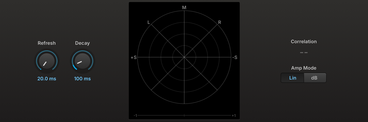
The Phase Meter displays the phase correlation of the signal. When the signal is fully mono, a vertical bar is displayed; with stereo channels that are fully out of phase, a horizontal bar is displayed.
To view a larger meter, drag the bottom edge of the module to resize it.
REFRESH (20–100 ms) sets how quickly the audio signal is measured, and DECAY (0–1,000 ms) sets how quickly the measurement fades from the display.
AMP MODE chooses a scale for the amplitude of the input signal, Linear or dB.
Press the EXTERNAL WINDOW button in the module title bar to open the meter in a separate window to view it even larger.
Spectrogram

The Spectrogram displays the frequency content of the signal over time, drawing each analysis frame as a column of color that scrolls across the display. Frequencies are on the Y-axis, increasing from bottom to top, time runs along the X-axis with the present at the right edge, and level is carried by the color. It makes the evolution of a sound legible at a glance — the decay of individual partials, the motion of a filter, the noise floor between notes — where a static spectrum shows only an instant.
To view a larger display, drag the bottom edge of the module to resize it.
FFT SIZE (1024–16384) defines the length of the frequency sampling window, trading frequency detail against time detail: larger sizes separate close partials but smear transients, and require more processing power.
WINDOW chooses the window function applied to each analysis frame: Hanning, Blackman-Harris, or Blackman.
COLOR MAP chooses the palette used to represent level: Fire, Turbo, Viridis, or Grayscale.
DURATION (1–30 s) sets how much history is shown across the width of the display; shorter spans scroll faster and show more detail of a single event.
MAX DB (−20–20 dB) sets the level reached by the top of the color scale, and DB RANGE (60–140 dB) sets how far below it the scale extends before the color reaches the background.
FREEZE in the upper right of the display holds the current image on screen and stops it scrolling, so a passage can be examined after it has played.
Press the EXTERNAL WINDOW button in the module title bar to open the display in a separate window to view it even larger.
Spectrum Analyzer

The Spectrum Analyzer displays the frequency content of the signal. Frequencies are displayed on the X-axis, increasing from left to right, and amplitude is displayed on the Y-axis, increasing from bottom to top.
To view a larger graph, drag the bottom edge of the module to resize it.
FFT SIZE defines the length of the frequency sampling window; larger sizes are more precise, but require more processing power.
WINDOW TYPE chooses the window function applied to each analysis frame: Hanning, Blackman-Harris, or Blackman.
MAX DB (−200–40 dB) sets the maximum value that can be displayed in the analyzer (the very top of the graph), and DB RANGE (10–200 dB) sets the range below the maximum value that will be displayed.
X SCALE chooses the scale used for the horizontal axis: Linear, Log, Semitones, or 3rd Octave. The labels on the left and top sides of the graph update as you adjust the Max dB, dB range, and X scale settings.
Press the EXTERNAL WINDOW button in the module title bar to open the graph in a separate window to view it even larger.
DRAW TYPE chooses how the frequency response will be drawn on the graph: as a single continuous line (Line), as multiple thin lines (Bin), or thick bars (Bands).
REFRESH (40–200 ms) sets how quickly the graph is re-drawn.
Tuner

The Tuner is a chromatic tuner with a needle-style meter, accurate to 1 cent increments. The Tuner is a helpful tool when adjusting a sample’s pitch with its keygroup Fine Tune parameter.
To view a larger tuner, drag the bottom edge of the module to resize it.
REFRESH (40–200 ms) sets how quickly the tuner reacts as the audio signal changes.
FREQ MIN and FREQ MAX set the lowest and highest notes the tuner will detect. Both are entered as MIDI notes and displayed as note names, not in Hz.
Press the EXTERNAL WINDOW button in the module title bar to open the tuner in a separate window to view it even larger.
Effect Rack
Effect Rack
The Effect Rack creates a new effects path inline where the Effect Rack module is added. Macros can be added to the front panel to control the effects that are added to the Effect Rack’s FX chain.
To view and edit the FX chain within an Effect Rack, go to the Tree view, expand the Effect Rack node, and choose the “chain” node. To add FX you can right-click the “chain” node and select new FX from the menu, or navigate to the EFFECTS view in the center column and click “+”.
FRONT PANEL You can add macros to the Effect Rack to control any parameter of an effect in the chain. To create a macro, right-click a parameter on an effect in a chain and choose ASSIGN TO EFFECT RACK MACRO. To change a macro’s name, double-click the macro’s name on the Effect Rack and enter a new name.
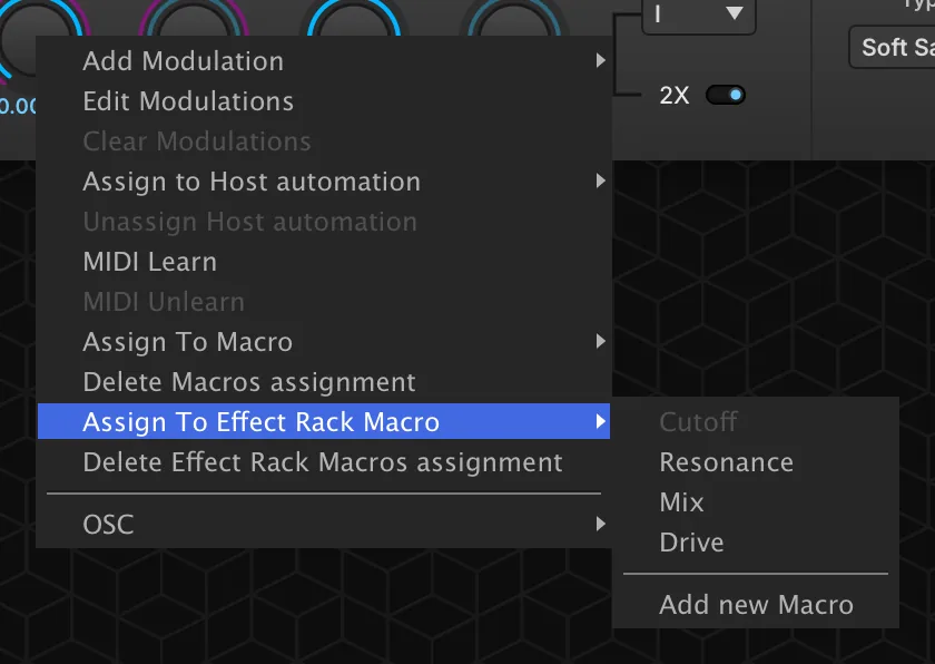
The overall level of the FX chain can be adjusted in the Tree view, or the chain can be disabled with the POWER button.
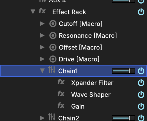
You can also create additional FX chains within a single Effect Rack by right-clicking the Effect Rack node in the TREE view and choosing ADD FX CHAIN. Chains are discrete and run in parallel, but utilize the same front panel for macros.
Filter
Tailor-made filters as Effect Racks.
MixXpander (screen example below) is a simple cutoff filter with mix control. Parallel and Stereo Xpander are made with two Xpander filters to create parallel or stereo filter effects.
CUTOFF (20–20,000 Hz) sets the frequency for the filter.
RESONANCE (0–100 %) adjusts how much emphasis is given to the cutoff frequency. MIX sets the balance between the dry (unaffected) and wet (affected) signal sent to the module’s output. DRIVE (−20–20 dB) sets the amount of overdrive used.
You can see the FX chains and edit the modules in the Tree view by choosing the node.
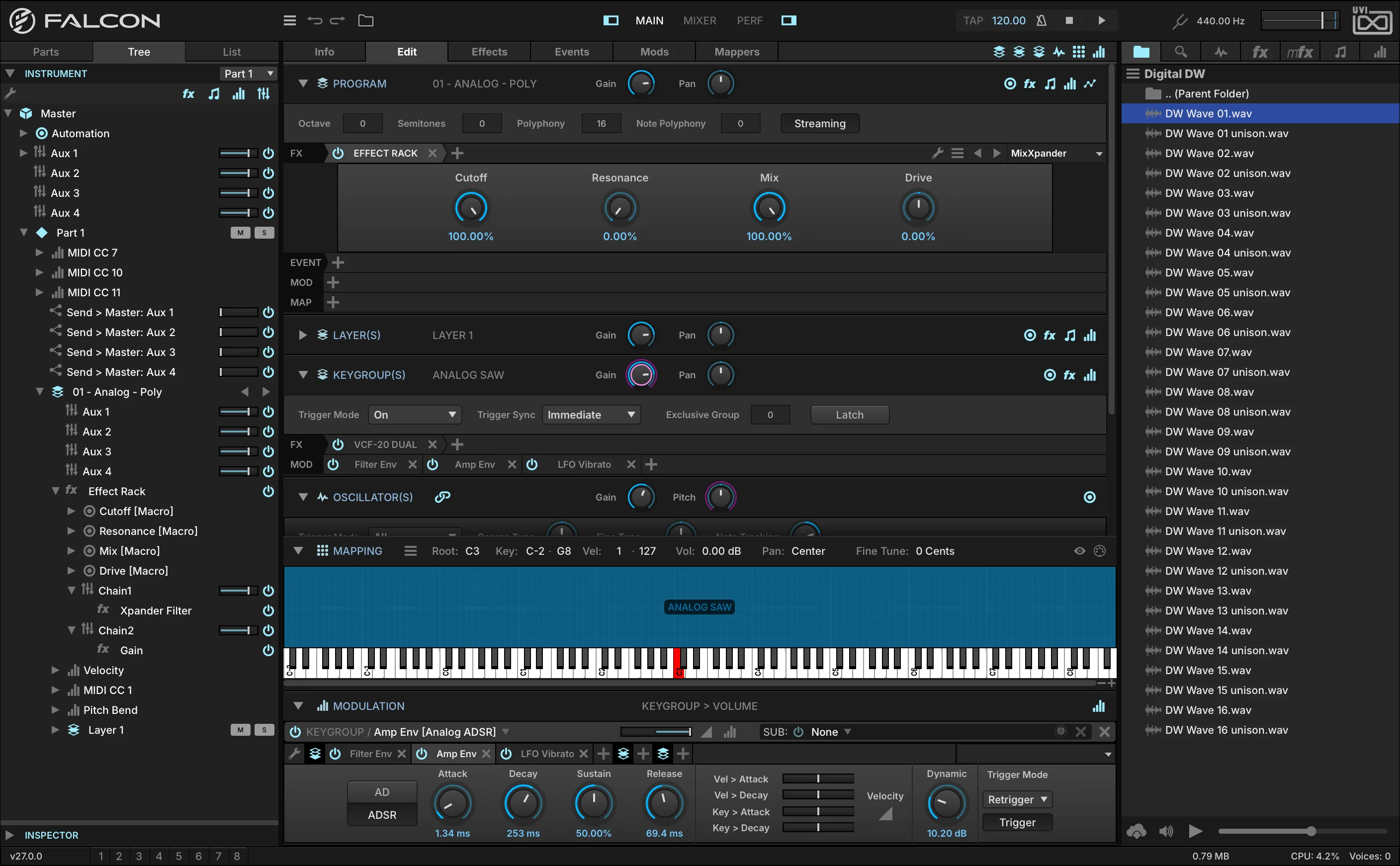
Fuzz4
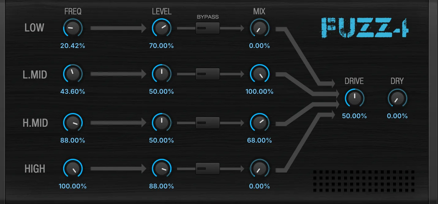
A 4-band distortion effect built from Wave Shaper and Xpander Filter modules.
FREQUENCY sets the band frequency. LEVEL sets the output volume of the band, BYPASS button enables or disables the band (FX chain), and MIX sets the balance between the dry (unaffected) and wet (affected) signal of the band.
DRIVE adjusts characteristics of the drive.
DRY sets the dry (unaffected) signal sent to the module’s output.
You can see the FX chains and edit the modules in the Tree view by choosing the node.
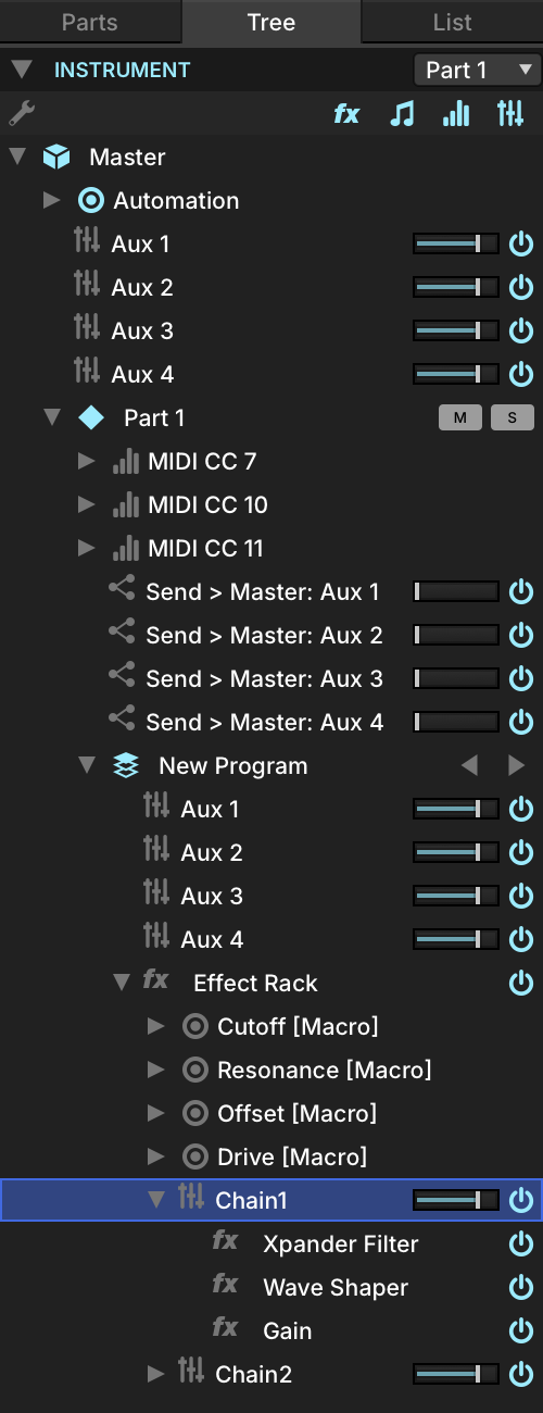
MaxMS
A Mid-Side Mastering module with High and Low bands for MID control.
Mid
COMP sets the compression amount. Mute the band with the MUTE switch, and the GAIN adjusts the band level.
CROSSOVER adjusts the frequency of the Low and High Mid bands.
Side
COMP sets the compression amount. Mute the band with the MUTE switch, and adjust the band level with GAIN.
You can see the FX chains and edit the modules in the Tree view by choosing the node.
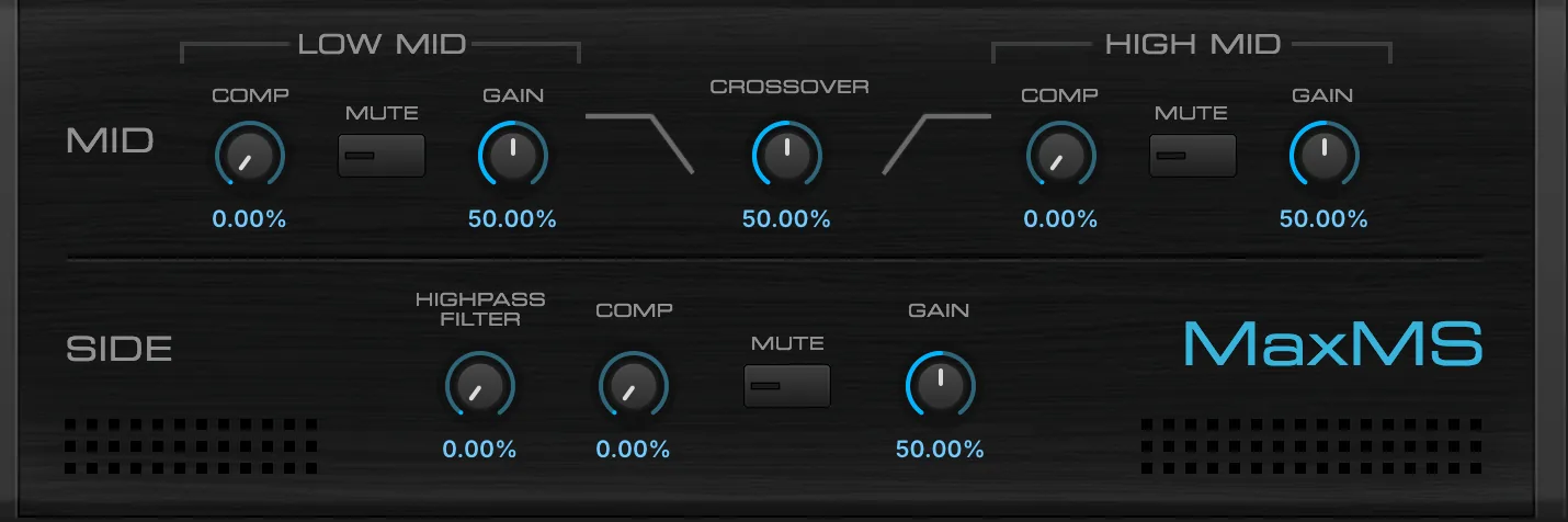
Feedback Machine

The Feedback Machine is a variant of the standard Effect Rack with a featured feedback loop, providing control over feedback amount, feedback injection delay, and overall mix amount.
For general instruction on using an Effect Rack see: Effects › Effect Rack.
Feedback Machine provides a featured feedback loop to your Chain. In its default state, Feedback Machine is identical to an empty Effect Rack in appearance and function, with the addition of 3 knobs on the front panel:
DELAY TIME (0.002–1 s) sets the time, in seconds, to delay the feedback signal before reinjection to the Chain.
FEEDBACK (0–100 %) sets the amount of the Chain’s output to reinject at its input (take care).
MIX (0–100 %) sets the wet/dry level of the effect.
Misc
Dispersor
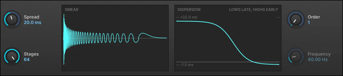
A transient smearing effect built from a chain of allpass filters, which delays each frequency by a different amount, with variable spread, frequency, order and stages.
Two displays sit between the controls. The left one, headed SMEAR, is the effect’s own impulse response, captured by running the current settings on an impulse rather than derived from them; it reads SMEAR (PART) when the smear has grown longer than the window can show. The right one, headed DISPERSION, plots group delay against frequency, measured against a linear-phase reference — a constant group delay disperses nothing, it is only latency — so the curve reads around a flat line the way an EQ does, with the extremes marked and labeled in milliseconds. At Order 1 it also reads LOWS LATE, HIGHS EARLY, the one direction that order can smear in.
SPREAD (0–1,000 ms) sets how far in time the transients are smeared.
STAGES (1–64) sets how many allpass stages are chained: more stages make a denser, smoother smear.
ORDER chooses first or second order. First order is the gentler smear and always runs lows late; second order is sharper and is what makes Frequency meaningful.
FREQUENCY (0–20,000 Hz) sets the center frequency of the dispersion curve. It applies to second order only, and is grayed out at Order 1.
Redux

A resampling effect useful for emulating the low-fidelity sound of various hardware units or extreme bit reductions.
FREQUENCY (200–44,100 Hz) sets the resampling frequency, with JITTER (0–100 %) introducing time variations to the resampling. BITS (1–32) sets the bit depth, and DITHER (0–200 %) sets the amount of dither (a type of low-level randomized noise).
TYPE chooses the style of resampling: DECIMATE inserts zeroes in between sampled values, and BLOCKER holds a sampled value until the next sampled value.
QUANTIZE LAW sets the type of quantization to one of two common algorithms: linear or mu-law (also known as μ-law).
Filter
FREQ (20–20,000 Hz) sets the frequency for the filter, and RES (0–100 %) adjusts how much the cutoff frequency is emphasized.
MODE chooses the type of filter: low-pass (LP), band-pass (BP), or high-pass (HP). POSITION chooses whether the filter is Off, before resampling (Pre), or after (Post).
Output
MIX (0–100 %) sets the balance between the dry (unaffected) and wet (affected) signal sent to the module’s output.
The ANTIALIASING toggle sets whether an anti-aliasing filter is enabled. When disabled, frequencies above half the resampling FREQUENCY may WRAP AROUND when resampled and cause unusual harmonics.
The SHAPING DISPLAY plots the module’s output waveform (blue) against a reference sine wave input (purple), so the effect of the current resampling, bit reduction, quantization and filter settings can be seen directly.
UVInyl

UVInyl is a vinyl simulation effect.
Choose the general vinyl characteristics with YEAR (1930, 1950, 1960, 1970, 1980, or 2000), RPM (33, 45, or 78 revolutions per minute), and amount of WEAR (0–100 %). Wear moves through eleven steps across its range, each one narrowing the record’s bandwidth and squashing its dynamics a little further.
Noise
To add noise to the record, add ELECTRICAL NOISE (−30–20 dB) or MECHANICAL NOISE (−30–20 dB) with their Gain controls.
Dust and Scratch
To add damage to the record, add DUST (−30–20 dB) or SCRATCH (−60–40 dB) with their Gain controls. The relative frequency of dust and scratches can be adjusted with the DUST AMOUNT (0–100 %) and SCRATCH AMOUNT (0–100 %) controls.
Output
The signal can be folded down to mono with the MONO toggle.