The Legacy FX modules were included in past versions of Falcon, UVI Player and MachFive. When older program and multi files are loaded, Legacy FX modules may be recalled.
For new programs and multis, it’s recommended to use the standard effects modules.
Delays
Dual Delay
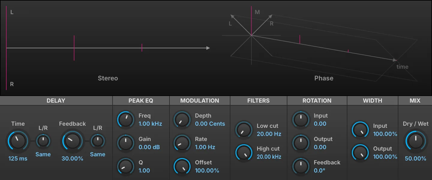
Dual Delay is a delay module with multiple controls for modifying one or both channels to produce a rich array of time-based effects, with an immersive interface to help visualize the stereo and phase adjustments being made.
Delay
TIME (0.001–5 s) sets the length of delay, in ms or bars/beats (if tempo-synced). FEEDBACK (0–100 %) chooses the percentage of signal fed back into the module. Both Time and Feedback have L/R controls that shorten one channel relative to the other: the display reads Same at the center, and L x or R x followed by a multiplier (0.10–1.00) applied to that channel only. Use 0.66 for dotted, 0.5 for half and 0.33 for triplet.
Peak EQ
A peak EQ located in the feedback loop. FREQ (20–20,000 Hz) sets the EQ frequency. GAIN (−20–20 dB) sets the EQ gain amount (+/-). Q (0.1–10) sets the filter’s bandwidth.
Modulation
DEPTH (0–20 ms) chooses a detune amount for the delay taps, and RATE (0.1–10 Hz) sets the speed of modulation. OFFSET (0–100 %) adjusts the phase offset of the delay line LFO.
Filters
The filters affect only the wet signal; the dry signal is not filtered. LOW CUT (20–4,000 Hz) rolls off lower frequencies, and HIGH CUT (1,000–20,000 Hz) rolls off higher frequencies.
Rotation
The Rotation section adjusts the phase of the INPUT (−1 to 1), OUTPUT (−1 to 1), and FEEDBACK signals.
Width
INPUT (0–100 %) adjusts the stereo spread of the signal input to the effect, and OUTPUT (0–100 %) adjusts the spread of the output signal.
Mix
DRY/WET knob sets the balance between the dry (unaffected) and wet (affected) signal sent to the module’s output.
Display
The display shows a visual representation of how the controls will affect the STEREO and PHASE output of the module.
FX Delay

FX Delay is a stereo delay with auto-panned stereo modulation.
DELAY TIME (0.01–10 s) sets the length of delay, in ms or bars/beats (if tempo-synced), and FEEDBACK (0–100 %) chooses the percentage of signal fed back into the module.
CUTOFF sets the type and amount of filter. At the center position, no filter is applied. To the right of center, a high-pass filter is applied, and further to the right raises the cutoff frequency. Likewise, further left of center applies a low-pass filter and drops the cutoff frequency.
The delay is also auto-panned; SPEED (0–20 Hz) controls the autopan rate, in Hz or bars/beats (if tempo-synced).
MIX (0–100 %) sets the balance between the dry (unaffected) and wet (affected) signal sent to the module’s output.
Fat Delay

Fat Delay uses multiple delay lines and diffusion to produce a dense delay tail.
DELAY TIME (0.01–10 s) sets the length of delay, in ms or bars/beats (if tempo-synced), and FEEDBACK (0–100 %) chooses the percentage of signal fed back into the module.
DIFFUSION (0–100 %) sets the density of the delay tap.
CUTOFF sets the type and amount of filter. At the center position, no filter is applied. To the right of center, a high-pass filter is applied, and further to the right raises the cutoff frequency. Likewise, further left of center applies a low-pass filter and drops the cutoff frequency.
MIX (0–100 %) sets the balance between the dry (unaffected) and wet (affected) signal sent to the module’s output.
Ping Pong Delay

Ping Pong Delay is a standard delay with additional stereo processing.
DELAY TIME (0.01–10 s) sets the length of delay, in ms or bars/beats (if tempo-synced), and FEEDBACK (0–100 %) chooses the percentage of signal fed back into the module.
CUTOFF sets the type and amount of filter. At the center position, no filter is applied. To the right of center, a high-pass filter is applied, and further to the right raises the cutoff frequency. Likewise, further left of center applies a low-pass filter and drops the cutoff frequency.
SPREAD (±100 %) controls the stereo spread of the module’s output. At zero, the output is mono; negative values feed the input to the left channel first, and positive values to the right channel first.
MIX (0–100 %) sets the balance between the dry (unaffected) and wet (affected) signal sent to the module’s output.
Simple Delay

Simple Delay is a general-purpose delay.
DELAY TIME (0–10 s) sets the length of delay, in ms or bars/beats (if tempo-synced), and FEEDBACK (0–100 %) chooses the percentage of signal fed back into the module.
CUTOFF sets the type and amount of filter. At the center position, no filter is applied. To the right of center, a high-pass filter is applied, and further to the right raises the cutoff frequency. Likewise, further left of center applies a low-pass filter and drops the cutoff frequency.
MIX (0–100 %) sets the balance between the dry (unaffected) and wet (affected) signal sent to the module’s output.
Stereo Delay

Stereo Delay offers a configurable stereo delay with separate delay paths for the left and right channels.
The left and right channels have independent delay time assignments; LEFT DELAY TIME (0–10 s) and RIGHT DELAY TIME (0–10 s) set the length of each channel’s delay, in ms or bars/beats (if tempo-synced). FEEDBACK (0–100 %) chooses the percentage of signal fed back into the module.
CUTOFF sets the type and amount of filter. At the center position, no filter is applied. To the right of center, a high-pass filter is applied, and further to the right raises the cutoff frequency. Likewise, further left of center applies a low-pass filter and drops the cutoff frequency.
MIX (0–100 %) sets the balance between the dry (unaffected) and wet (affected) signal sent to the module’s output.
Reverb
Gate Reverb

Gate Reverb provides a gate for cutting off the reverb decay abruptly.
PRE DELAY (0.01–2 s) sets the amount of delay before the wet signal is heard, in ms or bars/beats (if tempo-synced), and DECAY TIME (0–10 s) sets the duration of the reverb decay. GATE TIME (0.05–1 s) sets the time duration, in ms or bars/beats (if tempo-synced), until the gate is applied to the decaying signal.
HIGH DAMP (0–100 %) sets the amount of dampening applied to high frequencies.
MIX (0–100 %) sets the balance between the dry (unaffected) and wet (affected) signal sent to the module’s output.
Plain Reverb

Plain Reverb is a general-purpose reverb.
DECAY TIME (0–10 s) sets the duration of the reverb decay, and HIGH DAMP (0–100 %) chooses the amount of dampening applied to high frequencies.
MIX (0–100 %) sets the balance between the dry (unaffected) and wet (affected) signal sent to the module’s output.
Predelay Verb

Predelay Verb is a standard reverb fed through a delay line.
PRE DELAY (0.01–2 s) sets the amount of delay before the wet signal is heard, in ms or bars/beats (if tempo-synced), and DECAY TIME (0–10 s) sets the duration of the reverb decay. HIGH DAMP (0–100 %) chooses the amount of dampening applied to high frequencies.
MIX (0–100 %) sets the balance between the dry (unaffected) and wet (affected) signal sent to the module’s output.
Simple Reverb

Simple Reverb provides an optional low-pass or high-pass filter before the signal is fed into the reverb.
CUTOFF sets the type and amount of filter. At the center position, no filter is applied. To the right of center, a high-pass filter is applied, and further to the right raises the cutoff frequency. Likewise, further left of center applies a low-pass filter and drops the cutoff frequency.
DECAY TIME (0–10 s) sets the duration of the reverb decay, and HIGH DAMP (0–100 %) chooses the amount of dampening applied to high frequencies.
MIX (0–100 %) sets the balance between the dry (unaffected) and wet (affected) signal sent to the module’s output.
Modulation
Chorus

Chorus is a classic chorus, where the input signal is combined with multiple time- and pitch-modulated variations of the input signal for a shimmering unison effect.
SPEED (0.01–10 Hz) sets the speed of the modulation (in Hz, or bars/beats if tempo-synced), DELAY TIME (0–1 s) adjusts the amount of delay applied, and DEPTH (0–100 %) sets the depth of the effect.
MIX (0–100 %) sets the balance between the dry (unaffected) and wet (affected) signal sent to the module’s output.
Cross Phaser

Cross Phaser is a phaser that also applies auto-panning to produce a wider and more varied effect.
SPEED (0–10 Hz) sets the speed of the modulation (in Hz, or bars/beats if tempo-synced), and MIN FREQ (100–20,000 Hz) and MAX FREQ (100–20,000 Hz) set the minimum and maximum frequencies of the frequency sweep.
DEPTH (0–100 %) sets the depth of the effect, and FEEDBACK (0–100 %) sets the percentage of signal fed back into the module.
Phaser

Phaser is a classic phaser effect, where the input signal is phase modulated and fed back onto itself.
SPEED (0–10 Hz) sets the speed of the modulation (in Hz, or bars/beats if tempo-synced), and MIN FREQ (100–20,000 Hz) and MAX FREQ (100–20,000 Hz) set the minimum and maximum frequencies of the frequency sweep.
DEPTH (0–100 %) sets the depth of the effect, and FEEDBACK (0–100 %) sets the percentage of signal fed back into the module.
Rotary
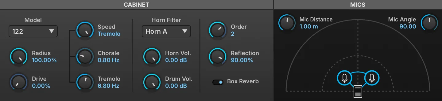
Rotary is a highly customizable speaker emulation effect modeled after the classic two-way rotating designs created for electric organs in the 1940s.
Cabinet
MODEL changes the cabinet type. RADIUS (0–100 %) sets the size of the cabinet. DRIVE (0–100 %) sets the amount of overdrive in the cabinet circuit.
SPEED sets the rotary style: BRAKE = none, CHORALE = slow speeds, TREMOLO = fast speeds.
Chorale and Tremolo speeds are controllable with the CHORALE (0.1–3 Hz) and TREMOLO (3–10 Hz) knobs below.
HORN FILTER sets the filter mode of the cabinet’s horn. HORN VOL (0–1) adjusts the rotating horn level. DRUM VOL (0–1) adjusts the rotating drum level.
ORDER (0–3) sets the number of box reflections being simulated. REFLECTION (0–100 %) sets the mix amount for the reflected signal.
BOX REVERB arms or disables a reverb on the cabinet.
Mics
MIC DISTANCE (0–10) sets the distance of the mics to the cabinet.
MIC ANGLE (0–180) sets the angle between the mics relative to the cabinet.
Filter
Auto Wah

Auto Wah is a wah pedal effect, with its filter frequency set automatically from the module’s input level.
GAIN (0.125–2) sets the input level to the module. SENSITIVITY (0.1–0.9) sets the intensity of the auto wah filter, and the Q (0–1) control sets the filter’s shape. DRIVE (0–1) applies post-filter overdrive.
FX Filter

The FX Filter module has two filters, low-pass and high-pass, applied in series.
LOW FREQ enables and sets the cutoff frequency for the low-pass filter; likewise, HIGH FREQ enables and applies the high-pass filter. The LOW Q (0–1) and HIGH Q (0–1) controls set the shape of each filter band.
Talkbox

Talkbox simulates the vowel shaping and filtering of a classic talkbox effect pedal.
FILTER MODE chooses the type of filter: low-pass (LP), high-pass (HP), or band-pass (BP). VOWEL MODE chooses the vowel sound for the filter.
CUTOFF (20–20,000 Hz) sets the frequency for the filter; the note name corresponding to the frequency is also displayed, for example, 2.00 KHZ (B5). RESONANCE (0–100 %) adjusts how much the cutoff frequency is emphasized.
Equalizer
2 Band EQ

The 2 Band EQ has Low and High bands.
Both bands have a FREQ control for setting their central frequency and a GAIN control for boosting or cutting around that frequency.
3 Band EQ

The 3 Band EQ has Low, Mid, and High bands. The Low and High bands have fixed frequency assignments, while the Mid band is adjustable.
The Mid band has a MID FREQ (120–12,000 Hz) control for setting the band’s central frequency and a MID Q (0–1) control for the band’s shape. Each of the three bands has a GAIN control for boosting or cutting its frequency.
8 Band EQ
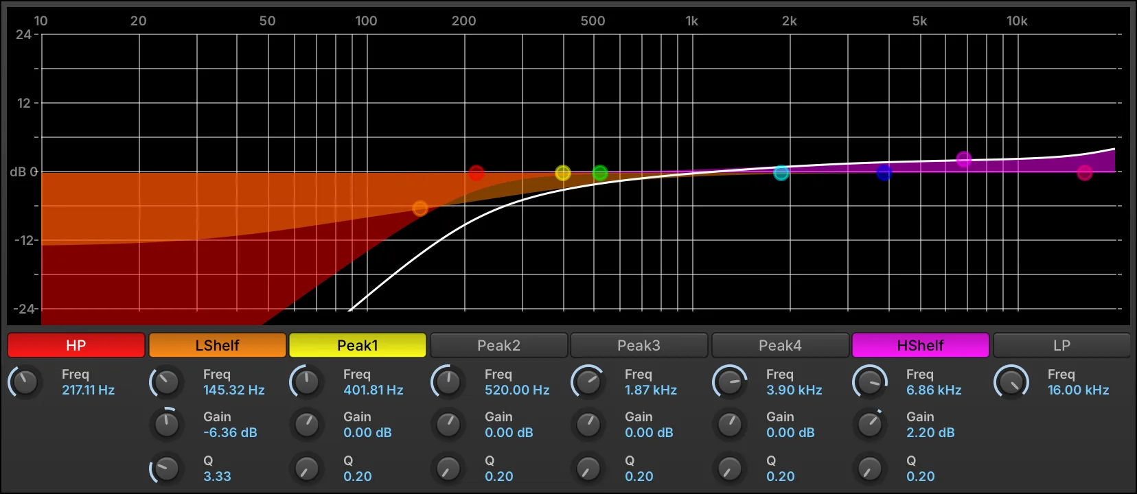
The 8 Band EQ is a parametric EQ with multiple types of bands, all laid out on a large, graphical display.
The eight bands are:
-
two rolloffs: high-pass (HP) and low-pass (LP).
-
two shelves: low-shelf (LSHELF) and high-shelf (HSHELF).
-
four peaks: PEAK1, PEAK2, PEAK3, PEAK4.
Each band can be enabled or bypassed by pressing its name. When enabled, the button is colored in.
All bands have a fully variable FREQ (10–20,000 Hz). The high-pass and low-pass bands have a fixed slope, while the remaining shelf and peak bands have adjustable GAIN (−30–20 dB) and Q (0.2–12).
In addition to the knobs and toggle switches, the bands can also be edited graphically in the frequency graph:
-
Press and drag a point to adjust its frequency by dragging right/left, or its gain by dragging up/down.
-
Press and drag a band’s color bars to adjust Q.
-
Right-click a point to enable/disable the band.
-
Double-click a point to return it to its default value.
-
When a band is selected, an information box is displayed in the upper left. As the band is adjusted, its Gain, Frequency, and Q values update in real time.
To view a larger graph, drag the bottom edge of the module to resize it.
Press the EXTERNAL WINDOW button in the module title bar to open the graph in a separate window to view it even larger.
Amp & Stereo
Rotary Simple

Rotary Simple is a single-speaker emulation of a rotary speaker.
SPEED (0–20 Hz) sets the rate of the speaker rotation, and DEPTH (1–100 %) sets the intensity of the effect; at higher Depth values, the pitch is also markedly affected.
Miking the speaker is also simulated, with MIC DISTANCE (1.1–20) setting the distance of the mic from the speaker.
MIX (0–100 %) sets the balance between the dry (unaffected) and wet (affected) signal sent to the module’s output.
Rotary Speaker

Rotary Speaker is a dual-speaker emulation of a rotary speaker, with an adjustable crossover.
CROSS FREQUENCY (20–10,000 Hz) sets the crossover point for the Low and High frequency bands. LOW SPEED (0–20 Hz) and HIGH SPEED (0–20 Hz) set the rate of the speaker rotation for each band, and DEPTH (1–100 %) sets the intensity of the effect; at higher Depth values, the pitch is also markedly affected.
Miking the speaker is also simulated, with MIC DISTANCE (1.1–20) setting the distance of the mic from the speaker.
Drive & Distortion
Double Drive

Double Drive is a filter sandwiched by two drive stages.
PRE DRIVE (0–100 %) sets the initial amount of overdrive, followed by the filters. HIGH FREQ and LOW FREQ controls set the amount of high-pass and low-pass filter applied (if any). Post-filter drive is applied with POST DRIVE (0–100 %), with GAIN (0–1) providing the final output level adjustment.
UVI Drive

UVI Drive is a drive module with a post-drive UVI Filter included.
DRIVE (0–100 %) sets the initial amount of drive applied, followed by the filter.
CUTOFF sets the type and amount of filter. At the center position, no filter is applied. To the right of center, a high-pass filter is applied, and further to the right raises the cutoff frequency. Likewise, further left of center applies a low-pass filter and drops the cutoff frequency. The Q (0–1) control sets the filter’s shape.
GAIN (0–1) provides the final output level adjustment.
Dynamics
Compressor

Compressor provides standard dynamics compression.
THRESHOLD (0–1) sets the level at which the compressor will be applied; when applied, RATIO (0–1) sets the slope above the threshold: 1 leaves the signal uncompressed (the default), lower values compress harder, and 0 holds the signal at the threshold. ATTACK (0.0001–0.1 s) and RELEASE (0.01–1 s) set the speed at which the compressor begins or stops processing the signal after it has crossed the threshold.
MAKEUP (1–16) applies a manual gain adjustment to compensate for the gain reduction of the compressor.
MIX (0–100 %) sets the balance between the dry (unaffected) and wet (affected) signal sent to the module’s output.
Limiter

Limiter is a standard limiter, compressing the signal with a fixed ratio that is higher than the ratios available with the Compressor.
GAIN (0.25–4) sets the input level to the module. THRESHOLD (0.1–1) sets the level at which limiting will be applied, and CEILING (0.1–1) sets the maximum output level. RELEASE (0–1 s) sets the speed at which the limiter stops processing the signal after it has fallen below the threshold.
MIX (0–100 %) sets the balance between the dry (unaffected) and wet (affected) signal sent to the module’s output.
UVI Mastering

UVI Mastering is a mastering processor for stereo mixes, such as Falcon’s main outs. It provides three-band tube saturation, a compressor and a limiter.
UVI Mastering has Low, Mid, and High bands. The crossover points between the bands are set with the LOW/MID FREQ (20–20,000 Hz) and MID/HIGH FREQ (20–20,000 Hz) controls.
Each band has a VOLUME (0.25–2) control, which sets the gain of the band before its tube saturation. TUBE AMOUNT (0–15) sets the saturation of every band. The bands are then summed and fed to a compressor with a fixed 4:1 ratio and automatic make-up gain, set with COMP ATTACK (0–500 ms) and COMP THRESHOLD (−20–0 dB), and finally to a limiter set by LIMITER THRESHOLD (−20–0 dB).
Misc
Beat Repeat

Beat Repeat slices the incoming audio on the grid that you specify, and when activated will repeat the most recent slice. This enables glitch effects and variations in a live performance or looped samples.
ACTIVE enables beat repeating; the most recent beat will be repeated until beat repeating is disabled. Once disabled, playback continues from where it left off.
TIME (0.001–4 s) sets the length of time that will be repeated, in ms or bars/beats (if tempo-synced).
MIX (0–100 %) sets the balance between the dry (unaffected) and wet (affected) signal sent to the module’s output.
FADETIME (0–0.05 s) sets the length of the fade applied at the start and end of each repeat, to soften the loop boundary.
Redux

Redux is a resampler for creating lo-fi effects such as extreme bit reduction.
Resampling
FREQUENCY (200–44,100 Hz) sets the resampling frequency, with JITTER (0–100 %) introducing time variations to the resampling. BITS (1–32) sets the bit depth, and DITHER (0–100 %) sets the amount of dither (a type of low-level randomized noise).
TYPE chooses the style of resampling: DECIMATE inserts zeroes in between sampled values, and BLOCKER holds a sampled value until the next sampled value.
QUANTIZE LAW sets the type of quantization to one of two common algorithms: linear or mu-law (also known as μ-law).
The ANTIALIASING toggle sets whether an anti-aliasing filter is enabled. When disabled, frequencies above half the resampling FREQUENCY may WRAP AROUND when resampled and cause unusual harmonics.
Filter
FILTER POSITION chooses whether the filter is off, before resampling (pre), or after (post). FILTER MODE chooses the type of filter: low-pass (LP), high-pass (HP), or band-pass (BP).
FILTER FREQ (20–20,000 Hz) sets the frequency for the filter, and FILTER RES (0–100 %) adjusts how much the cutoff frequency is emphasized.
Output
MIX (0–100 %) sets the balance between the dry (unaffected) and wet (affected) signal sent to the module’s output.
Ring Modulator

Ring Modulator combines the input signal with a modulation frequency, and both subtracts and adds the modulation frequency to the input frequency. For example, with an input of 600 Hz and a modulation frequency of 250 Hz, the output will include both 350 Hz (600 minus 250) and 850 Hz (600 plus 250).
FREQ (0.1–2,000 Hz) sets the frequency of the modulation signal.
MIX (0–100 %) sets the balance between the dry (unaffected) and wet (affected) signal sent to the module’s output.
Robotizer

Robotizer starts with a ring modulator, with some additional modulations.
FREQ (0.1–2,000 Hz) sets the frequency of the ring modulation, and DEPTH (0–100 %) adjusts the intensity of the modulation. FM (0.25–20 Hz) controls a modulation signal that modifies the ring modulation frequency.
CUTOFF sets the type and amount of filter. At the center position, no filter is applied. To the right of center, a high-pass filter is applied, and further to the right raises the cutoff frequency. Likewise, further left of center applies a low-pass filter and drops the cutoff frequency.
MIX (0–100 %) sets the balance between the dry (unaffected) and wet (affected) signal sent to the module’s output.
UVI Destructor

UVI Destructor is a resampler and bit reducer, with optional overdrive and filter following the bit depth and sample rate reduction.
BIT SIZE (1–24) sets the bit depth, and SAMPLE RATE (2,000–48,000 Hz) sets the resampling frequency.
DRIVE (0–100 %) sets the amount of pre-filter overdrive applied.
CUTOFF sets the type and amount of filter. At the center position, no filter is applied. To the right of center, a high-pass filter is applied, and further to the right raises the cutoff frequency. Likewise, further left of center applies a low-pass filter and drops the cutoff frequency.
MIX (0–100 %) sets the balance between the dry (unaffected) and wet (affected) signal sent to the module’s output.